9.3 JUNOS BGP Minimum Configuration
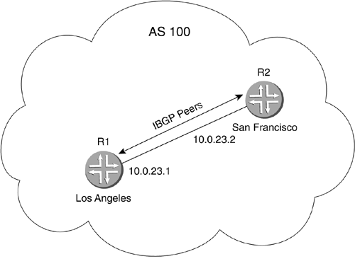
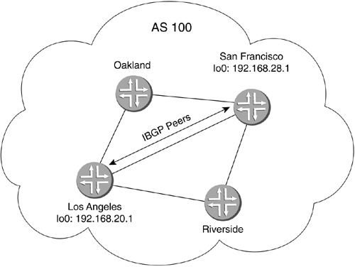
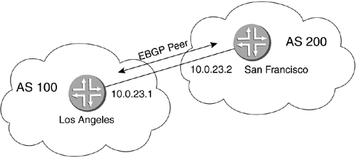
| Previous sections of this chapter have discussed the fundamentals of BGP. This section will now take a look at basic configuration for both internal and external peering sessions. 9.3.1 Minimum Configuration ParametersActivation of BGP in JUNOS is relatively straightforward. The following example shows the combined parameters necessary for both IBGP and EBGP peering sessions. These are listed together so you can become familiar with the various parameters that are necessary for both types of sessions. routing-options { autonomous-system autonomous-system; } protocols { bgp { group group-name { type type; neighbor address; local-address address; peer-as autonomous-system; } } } } The next two sections will show the minimum requirements for both internal and external peering sessions. 9.3.2 IBGP Minimum ConfigurationThe following example lists the minimum configuration parameters for an IBGP peering session under the [edit routing-options] hierarchy the ASN of the local system and under the [edit protocols bgp] hierarchy, group, type, and neighbor. routing-options { autonomous-system autonomous-system; } protocols { bgp { group group-name { type type; neighbor address; } } } 9.3.2.1 IBGP Between Physical InterfacesWe will now establish a peering session between Los Angeles and San Francisco. Even though a minimum configuration is shown, two scenarios will actually be covered: simple peering between physical interfaces (see Figure 9-23) and peering between loopback interfaces. The latter method is more common, but understanding both is necessary. Figure 9-23. IBGP Configuration ”Physical Interface The configuration for router Los Angeles is shown below. The ASN for Los Angeles is 100; the group name for the peering session is IBGP. The type of session, of course, is internal, and the neighbor that we are peering with is 10.0.23.2 . Remember, for now we are peering only through the physical interfaces. routing-options { autonomous-system 100 ; } protocols { bgp { group IBGP { type internal ; neighbor 10.0.23.2 ; } } } The above configuration can be created with the following two commands while in [edit] mode. [edit] lab@LosAngeles# set routing-options autonomous-system 100 [edit] lab@LosAngeles# set protocols bgp group IBGP type internal neighbor 10.0.23.2 The configuration for San Francisco is shown next. The ASN for San Francisco is 100; the group name for the peering session is IBGP. The type of session, of course, is internal, and the neighbor that we are peering with is 10.0.23.1 . routing-options { autonomous-system 100 ; } protocols { bgp { group IBGP { type internal ; neighbor 10.0.23.1 ; } } } Now, because we are only peering between physical interface addresses, we are done. We can issue several commands to check the state of the peering session. We choose to use the show bgp neighbor command. When we issue this command on Los Angeles, we see the output as shown below. The first highlighted item shows the peer address and port number, peer AS100, local address and port, and local AS100. The type of session is internal, and it is in the Established state, which indicates that the peering session is up. lab@LosAngeles> show bgp neighbor 10.0.23.2 Peer: 10.0.23.2+179 AS100 Local: 10.0.23.1+1037 AS100 Type: Internal State: Established Flags: <> Last State: OpenConfirm Last Event: RecvKeepAlive Last Error: Open Message Error Options: <Preference HoldTime Refresh> Holdtime: 90 Preference: 170 Number of flaps: 0 Error: 'Open Message Error' Sent: 1 Recv: 0 Peer ID: 192.168.28.1 Local ID: 192.168.20.1 Active Holdtime: 90 Keepalive Interval: 30 NLRI advertised by peer: inet-unicast NLRI for this session: inet-unicast Peer supports Refresh capability (2) Table inet.0 Bit: 10000 Send state: in sync Active prefixes: 0 Received prefixes: 0 Suppressed due to damping: 0 Last traffic (seconds): Received 1 Sent 1 Checked 1 Input messages: Total 8 Updates 0 Refreshes 0 Octets 152 Output messages: Total 12 Updates 0 Refreshes 0 Octets 282 Output Queue[0]: 0 9.3.2.2 IBGP Between Loopback InterfacesNow that we have seen how to configure IBGP between physical interface addresses, let's take a look at configuring an IBGP session between loopback interface addresses (see Figure 9-24). We know from our earlier discussion of IBGP that it is preferable to use the loopback interface address for IBGP peering. This allows our peering session to remain up as long as a single physical interface to our router is up. Figure 9-24. IBGP Configuration ”Logical Interface First, we have the required parameters necessary for IBGP peering between loopback interfaces. The only real change here is the addition of the local-address statement. This allows us to peer between loopback addresses because, instead of using our physical interface address to establish the peering session, we will use our own loopback address. Make sure when configuring for this type of peering that you do the following two things: set the neighbor address on each router to the loopback address of the router you wish to peer with, and set the local-address statement to the local system's loopback interface IP address. If either of these is left out, the peering session will not become active. In addition, there must be either an IGP running on both routers with the loopback interfaces being advertised, or static routes set up to the neighbor router for the loopback address. The local systems must know how to route to the loopback address to establish the peering session. If none of these routing mechanisms is in place, the IBGP session will not be established. routing-options { autonomous-system autonomous-system; } protocols { bgp { group group-name { type type; neighbor address; local-address address; } } } } The configuration for router Los Angeles is shown below. The ASN for Los Angeles is 100; the group name for the peering session is IBGP. The type of session, of course, is internal, and the neighbor that we are peering with is 192.168.28.1 , which we know is the loopback interface address of the router we will peer with. In addition, we now include the local-address statement, which, in this case, is 192.168.20.1 . We now have a configuration for IBGP to peer with our neighbor's loopback interface. routing-options { autonomous-system 100; } protocols { bgp { group IBGP { type internal; neighbor 192.168.28.1; local-address 192.168.20.1; } } } } We choose to use the show bgp neighbor command. When we issue this command on Los Angeles, we see the output listed below. The first highlighted item shows the peer address and port number, peer AS100, local address and port, and local AS100. The type of session is internal, and the state is established, which indicates the peering session is up. In this example, you will also see the Local Address field used. In this case, it shows our own loopback interface address. lab@LosAngeles> show bgp neighbor 192.168.28.1 Peer: 192.168.28.1+179 AS100 Local: 192.168.20.1+1038 AS100 Type: Internal State: Established Flags: <> Last State: OpenConfirm Last Event: RecvKeepAlive Last Error: None Options: <Preference LocalAddress HoldTime Refresh> Local Address: 192.168.20.1 Holdtime: 90 Preference: 170 Number of flaps: 0 Peer ID: 192.168.28.1 Local ID: 192.168.20.1 Active Holdtime: 90 Keepalive Interval: 30 NLRI advertised by peer: inet-unicast NLRI for this session: inet-unicast Peer supports Refresh capability (2) Table inet.0 Bit: 10000 Send state: in sync Active prefixes: 0 Received prefixes: 0 Suppressed due to damping: 0 Last traffic (seconds): Received 18 Sent 18 Checked 18 Input messages: Total 2 Updates 0 Refreshes 0 Octets 38 Output messages: Total 4 Updates 0 Refreshes 0 Octets 102 Output Queue[0]: 0 Now that we have seen two methods of creating our IBGP sessions, we will move on to creating EBGP session. 9.3.3 EBGP Minimum ConfigurationThe following example lists the minimum configuration parameters for an EBGP peering session. Under the [edit routing-options] hierarchy the ASN of the local system is specified, and under the [edit protocols bgp] hierarchy, group, type, neighbor, and peer-as are specified. Though local-address is not necessary for a typical directly connected interface peering session, you will see how the local-address and multihop statement can be used in the second EBGP configuration scenario. routing-options { autonomous-system autonomous-system; } protocols { bgp { group group-name { type type; neighbor address; peer-as autonomous-system; } } } } 9.3.3.1 EBGP Between Physical InterfacesWe will now establish a peering session between Los Angeles and San Francisco. No topology diagram is necessary as there are only two routers involved. Even though there are several methods by which an EBGP peering session can be established, we will only be looking at the directly connected scenario (see Figure 9-24). Multihop EBGP peering is addressed separately in Sections 9.2.5.3,9.4.2.21 and 10.3.3. The configuration for router Los Angeles is shown next as well as the topology in Figure 9-25. The ASN for Los Angeles is 100; the group name for the peering session is EBGP. The type of session, of course, is external, and the neighbor that we are peering with is 10.0.23.2 . Remember, for now we are peering only through the physical interfaces. Figure 9-25. EBGP Configuration ”Physical Interface routing-options { autonomous-system 100 ; } protocols { bgp { group EBGP { type external ; neighbor 10.0.23.2 ; peer-AS200; } } } } The configuration for San Francisco is shown next. The ASN for San Francisco is 200; the group name for the peering sessions EBGP. The type of session, of course, is external, and the neighbor that we are peering with is 10.0.23.1 . routing-options { autonomous-system 200 ; } protocols { bgp { group EBGP { type external ; neighbor 10.0.23.1 ; peer-AS100; } } } } Now, since we are only peering between physical interface addresses, we are done. We can issue several commands to check the state of the peering session. We choose the show bgp neighbor command. When we issue this command on Los Angeles, we see the output listed below. The first highlighted item shows the peer address and port number: peer AS200, local address and port, and local AS100. The type of session is external, and the state is Established , which indicates the peering session is up. lab@LosAngeles> show bgp neighbor 10.0.23.2 Peer: 10.0.23.2+179 AS200 Local: 10.0.23.1+1040 AS100 Type: External State: Established Flags: <> Last State: OpenConfirm Last Event: RecvKeepAlive Last Error: Open Message Error Options: <Preference HoldTime PeerAS Refresh> Holdtime: 90 Preference: 170 Number of flaps: 0 Error: 'Open Message Error' Sent: 1 Recv: 0 Peer ID: 192.168.28.1 Local ID: 192.168.20.1 Active Holdtime: 90 Keepalive Interval: 30 Local Interface: fe-0/1/0.0 NLRI advertised by peer: inet-unicast NLRI for this session: inet-unicast Peer supports Refresh capability (2) Table inet.0 Bit: 10000 Send state: in sync Active prefixes: 0 Received prefixes: 0 Suppressed due to damping: 0 Last traffic (seconds): Received 2 Sent 2 Checked 2 Input messages: Total 3 Updates 0 Refreshes 0 Octets 57 Output messages: Total 7 Updates 0 Refreshes 0 Octets 187 Output Queue[0]: 0 9.3.3.2 RIDBGP uses an RID to identify the system from which an advertisement comes. In the case of JUNOS, one either has to be defined in the [edit routing-options] hierarchy or taken from the first interface with an IP address assigned, typically the loopback interface. The simplest way to figure out what your RID is by assigning one. The following example shows the set command to use while in [edit] mode. set routing-options router-id 100.100.100.100 routing-options { router-id 100.100.100.100; } |
EAN: 2147483647
Pages: 176


