Topologies of Server Load Balancing
| The science of implementing networks, whether based on Layers 2, 3, 4, or 7, is never exact. There are many ways to skin the proverbial cat, and while the topology examples shown here are designed to convey some of the common approaches and best practices, they are merely that: examples. Every network, application, and implementation is different, and finding the approach best suited is a skill that comes only from experience. Most server load balancing topologies can be broadly grouped into one of the following three types:
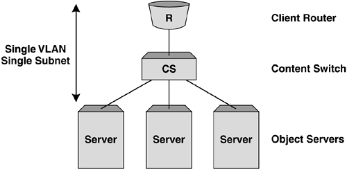
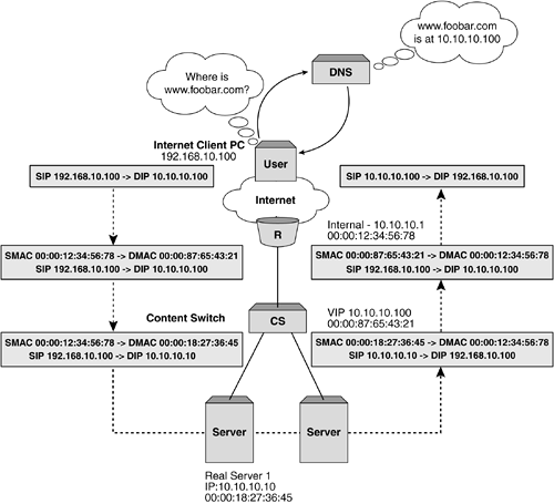
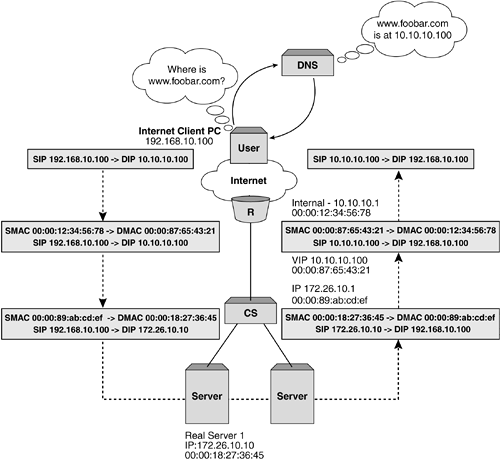
Layer 2 (Bridging) Server Load BalancingThe most simplistic implementation of server load balancing is using the Layer 2 or bridging model. In this instance, all interfaces on the content switch are in the same VLAN and IP subnet as both the client-side router and the object servers. The content switch presents a VIP in this subnet, which represents the object servers below. Figure 5-1 shows a simplistic representation of a Layer 2 or bridging implementation. Figure 5-1. Example Layer 2 SLB topology. The primary advantage of deploying a solution based on Layer 2 server load balancing is simplicity. The content switch can be placed into the network without any topology alteration other than the introduction of another bridge hop between the client-side router and the object servers. No restructuring of the IP addressing is required to implement the content switch in this instance, thus eliminating changes to routing tables on the client-side router and default gateways on the object servers. Traffic flow in Layer 2 server load balancingLet's walk through an example TCP session using Layer 2 server load balancing for HTTP to see what's involved for all components in the network. Figure 5-2 shows an example Layer 2 server load balancing infrastructure and client. Let's assume that the client is establishing an HTTP connection to the Web site housed in the 10.10.10.0 network that is being server load balanced by the content switch with VIP 10.10.10.100. Figure 5-2. Example TCP session flow for Layer 2 SLB. The flow from client toward the server looks like:
It's important to note that when the TCP SYN frame, along with all subsequent frames in the TCP session, arrives, the server has no evidence of the involvement of the content switch. That is to say that the Layer 2 and 3 source address information is identical to that which would have been received if the client was talking directly to the object server. For the flow from the server to the client, the reverse is true:
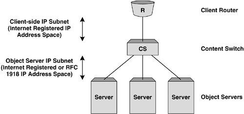
An important point to note during this process is that neither the client nor the object server has visibility of the load balancing that is taking place. The client sees a continuous connection between itself and the VIP owned by the content switch, while the server sees the client connection without evidence of the content switch being involved. Layer 3 (Routing) Server Load BalancingProbably the most common implementation of server load balancing is Layer 3 or routing SLB. This is conceptually similar to Layer 2 SLB, but with the distinction that the client router and object servers exist in different Layer 2 VLANs and IP subnets. The content switch can present a VIP in either of these subnets, or in a subnet without a physical interface in certain instances. Figure 5-3 shows a simplistic representation of a Layer 3 or routing implementation Figure 5-3. Example Layer 3 SLB topology. There are two primary advantages of deploying Layer 3 server load balancing:
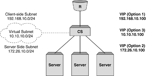
So, where does the VIP live in this type of Layer 3 SLB topology? Well, there are basically three options. First, and most commonly, the VIP can be a member of the client-side IP subnet. In this instance, the router does not need to be concerned with the remote subnet housing the object servers, and this allows the deployment to preserve the use of the costly registered Internet addresses. Second, the VIP can be a member of the same subnet as the object server. In this instance, the object server subnet must be publicly routable or translated by a NAT device further upstream. Finally, the VIP may be a member of a subnet not directly attached to the content switch. In this instance, the client router needs to be configured with a static route pointing to the interface of the content switch for the "virtual subnet" housing the VIP. Another alternative to the use of static routes is the use of a dynamic routing protocol. Many content switch vendors allow the configuration of dynamic routing protocols such as OSPF, RIP v2, and BGP with the added option of advertising a specific 32-bit host route corresponding to the VIP depending on its availability. Figure 5-4 shows the options of which subnet the VIP may belong to. Figure 5-4. Where does the VIP live in Layer 3 SLB? Traffic Flow in Layer 3 Server Load BalancingFundamentally, the traffic flow in Layer 3 SLB is the same as with Layer 2, but with two subtle differences. First, as the content switch is now routing rather than switching the frames between the client and server, the source MAC address is changed to that of the server-side router interface on the content switch. As with any switching and routing infrastructure, this fundamental difference remains with content switching. If we look at the example frame flow from the Layer 2 SLB implementation shown earlier, the steps are very similar and are shown in Figure 5-5:
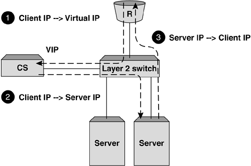
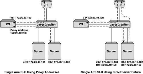
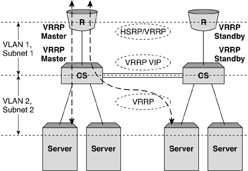
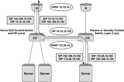
Figure 5-5. Example TCP session flow for Layer 3 SLB. Single Arm Server Load BalancingThe final topology implementation option we will look at is commonly known as single arm server load balancing. For this implementation, the content switch sits logically to the side of the Layer 2 or 3 infrastructure and consequently out of the data path. While the general principles are similar to those seen in Layer 2 and 3 SLB, the traffic flow can be somewhat different. The main issue when implementing single arm SLB is how to deal with return path traffic from the object servers to the client. In the Layer 2 and 3 topology examples we saw earlier, the return traffic from the object server to the client is forced to pass back through the content switch by virtue of the fact that it is always directly in the data path . When implementing single arm SLB, without considering return traffic, we will end up with a broken TCP or UDP session, as the reverse address translations will not take place and the client will see the object server's IP address respond to a request that was originally sent to the VIP. Figure 5-6 illustrates this problem. Figure 5-6. Problems with return traffic in single arm SLB can mean that the client ends up with a broken TCP or UDP session. There are two options to deal with return traffic when implementing single arm SLB or any other topology instance where the traffic flow from server to client might bypass the content switch: proxy addresses or direct server return. Proxy AddressesThe first solution to this issue is the use of proxy addresses. In this instance, when the content switch translates the frames and forwards them to the server, the source IP address will be translated to one owned by the content switch. This will have the effect of forcing traffic back to the content switch before returning to the client, as the object server will believe that the connection originated there. The main disadvantage of using proxy addresses is that the client IP address details will no longer be preserved through to the object servers; therefore, some of the elegance in the transparency of standard Layer 2 and 3 topologies is lost. The most notable example of this as an issue is the logging of IP address details within Web and application servers, specifically where such information is required as a mechanism for nonrepudiation. Figure 5-7 shows an example traffic flow when a proxy IP address is used for single arm SLB. Figure 5-7. The difference in traffic flow for single arm SLB implementations . Direct Server ReturnDirect Server Return (DSR) is useful in managing the issue of implementing single arm SLB, but also provides an advantage in environments where the majority of the data flow is from the server to the client. HTTP and FTP are examples of protocols where a large proportion of the data transfer takes place from the object server to the client, with the client sending only the initial GET request and TCP ACK messages. In DSR mode, the content switch will NAT only the destination MAC address to that of the object server before forwarding the frame on. For this to work correctly, the object server also needs to be configured to respond to IP connections that are destined for the VIP, which is typically implemented using a loopback address or subinterface; for example, in Linux terms: eth0 Link encap:Ethernet HWaddr 00:A0:CC:33:74:EB inet addr:172.26.10.101 Mask:255.255.255.0 UP BROADCAST RUNNING MULTICAST MTU:1500 Metric:1 RX packets:297581 errors:0 dropped:0 overruns:0 frame:0 TX packets:266104 errors:1 dropped:0 overruns:0 carrier:2 collisions:79 txqueuelen:100 Interrupt:10 Base address:0x1300 lo Link encap:Local Loopback inet addr:172.26.10.100 Mask:255.255.255.0 UP LOOPBACK RUNNING MTU:3924 Metric:1 RX packets:1855 errors:0 dropped:0 overruns:0 frame:0 TX packets:1855 errors:0 dropped:0 overruns:0 carrier:0 collisions:0 txqueuelen:0 Implementing this loopback interface will allow the IP stack on the server to respond to requests for the VIP, but also use this address on return packets for the client. Implementing High Availability for SLBThe implementations we've considered so far are simplistic, single component examples. While for some real-world situations this may prove suitable, commonly in today's 24 x7 Internet, the requirement for "five nines" availability means that most implementations will need to avoid a single component failure causing a service disruption of any notable length. Any high availability (HA) implementation will require the addition of more components and the use of resiliency protocols such as VRRP, HSRP, and the Spanning Tree Protocol (STP) to guarantee correct operation. HSRP stands for Hot Standby Router Protocol and is a common virtual router protocol implemented by Cisco Systems. For the purposes of this discussion, we will use the term VRRP to refer to both VRRP and HSRP as redundancy protocols. Another option that might be considered is multihoming the object servers to remove the risk of a NIC card failure taking a server out of operation. Multiple Content Switches and RoutersThe most obvious first step in developing an HA design is to add resilient content switches and routers. In the simple examples we've considered so far, we've seen a single Internet feed provided by a single router. Most Internet hosting environments now provide multiline feeds as standard, and many large enterprises are becoming so reliant on the Internet as a service that they are opting for multiple Internet feeds typically provided by different ISPs. When using a simple HA setup with two routers and two content switches, VRRP instances must be implemented on the single subnet for Layer 2 SLB and on both subnets for Layer 3 SLB. This can be coupled with VRRP running on the upstream routers to provide resilient Layer 2 and 3 paths throughout the network. Figure 5-8 shows a resilient Layer SLB infrastructure utilizing VRRP instances on both the content switches representing the VIP and the Internet routers. By setting the VRRP priorities to ensure that the left side of each redundant pair is master, a clean data path can be ensured. Client traffic will be naturally drawn in through the left-hand, master router and forwarded to the VIP instance on the left-hand content switch. For return traffic, the object server will forward traffic toward its default gateway, the VRRP instance in subnet 2 on the content switches, which will in turn forward back to the VRRP instance in subnet 1 on the routers. In this instance, the standby content switch on the right-hand side is used only to forward traffic at Layer 2 to the object servers attached directly to it and is performing no server load balancing. Figure 5-8. Layer 3 SLB implementation with VRRP for resilience. Figure 5-9 shows the basic traffic flow for this HA implementation. In this instance, the content switch has two cross connects, one in the VLAN connecting the client-side routers and the other in the VLAN containing the servers. This dual cross connect could be replaced by an 802.1q VLAN tagged link comprising both VLANs on a single physical link. In the example shown, traffic entering from the primary router and being processed by the primary content switch may be forwarded across the server VLAN cross connect and to an object server directly attached to the backup content switch. It is important to note that in this instance the session processing and consequent session entry are held in the primary content switch. Figure 5-9. Traffic flow in a resilient Layer 3 SLB topology. Let's consider two possible failure scenarios for this topology. A failure on the primary router would have the following effects:
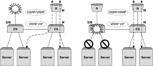
In this instance, a component failure will cause a minor service interruption while the VRRP statuses on each subnet stabilize. The second possible failure scenario is a failure on the primary content switch, which would have the following effects:
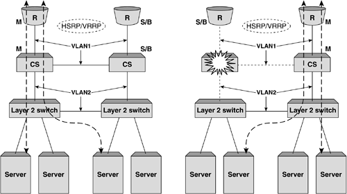
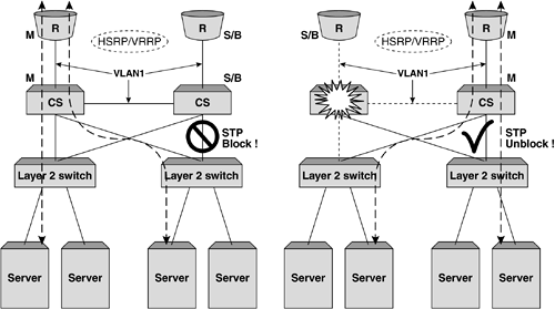
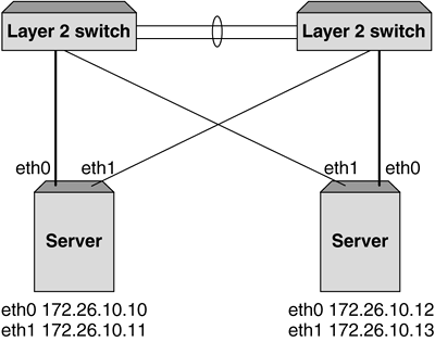
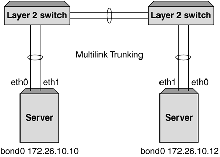
Figure 5-10 shows these two failure scenarios in more detail. Figure 5-10. Two failure scenarios in a VRRP implementation. On the left, a failed router would result in the primary content switch changing, whereas on the right, a failure of the primary content switch would result in all servers directly attached becoming unavailable. Adding Port Density and Resilience with Layer 2 SwitchesThe second consideration in adding greater resilience to a topology is increasing the server availability using Layer 2 switching. Commonly, additional Layer 2 switches are used to increase port density when using content switches, as the price per port cost of a standard Layer 2 switch is considerably lower. In Chapter 4, The Concepts of Content Switching , we saw that the processing power of a content switch is measured chiefly in terms of sessions rather than packets, which means that using a Layer 2 switch to provide greater port density does not mean a reduction in the overall capacity of the network. Importantly, the addition of Layer 2 switches will not only increase the port density but also the resilience of the network. First, the object servers effectively become multihomed even with a single NIC implementation, as each Layer 2 switch attaches to both content switches. Second, the failure of a content switch, as seen in Figure 5-10, will no longer result in the loss of operation of the servers attached directly to it. Later we will see how the addition of multihoming techniques for the objects servers combined with additional Layer 2 switch implementation can increase this resilience further. Figure 5-11 shows the first option for implementing Layer 2 switches for increased port density without the need to use STP to avoid Layer 2 bridging loops . Figure 5-11. Using Layer 2 switches without STP. Using the Layer 2 switches in this configuration without a Layer 2 bridging loop can still provide better server resilience as shown. In this example, the failure of a content switch does not result in the removal from service of servers as a Layer 2 path is preserved. The use and operation of VRRP remains identical to that described previously with a failure on the primary content switch resulting in the fail-over of all VRRP instances in the topology to the standby devices and the traffic flow recovering within two to three seconds. One disadvantage of the topology described previously is that the failure of the cross-connect between the two Layer 2 switches still results in a loss of service of the servers attached to the right-hand switch. An alternative to this topology is to create a fully meshed topology between the Layer 2 switches and content switches and use the STP to block the desired ports during normal operation. Here, the topology is less prone to cable (or port) failures, as alternate paths exist between each switch. Figure 5-12 shows an implementation using STP to block redundant links. It is advantageous to alter the STP priorities within the mesh topology to ensure that the correct link blocks as shown. In this instance, a failure on the primary content switch would result in the blocked link changing to a forwarding state and traffic recovering within the bounds of normal STP convergence. If anything, the primary disadvantage of implementations using STP is slower convergence times. In modern switches, this failure time can be greatly reduced with the implementation of fast-altering port states using "Port Fast" and other settings. Figure 5-12. Using Layer 2 switches and STP for greater resilience to link or Ethernet port failures. Increasing Server Resilience with MultihomingThe final alternative for increasing resilience and availability in the network design is the implementation of multihoming or dual homing. Multihoming refers to the ability to attach the object servers to the network using two NICs. In content switching topologies, there are two ways to achieve this effect. First, as shown in Figure 5-13, the interfaces can be given unique IP addresses in the same subnet (or different subnets). In this instance, each interfaces acts independently and will respond to traffic only targeted directly at its IP address. One common way to implement this approach when using content switches as load balancers is to define the secondary interfaces (in this example shown as eth1) as backup real servers in the configuration. The failure of the primary interface on any object server will result in the server being marked down and the backup server being brought into operation. As only the NIC has failed, the server is still capable of processing traffic and the content switch can begin assigning new user sessions to the server through the secondary interface card. In practice this mechanism is not useful when used for load sharing among multiple interfaces, as in many operating systems even though traffic may enter through both interfaces, return traffic from the server only egresses a single interface. This is obviously dependent on the server and operating systems vendor and should be investigated in more detail. Figure 5-13. Multihoming servers using secondary IP addresses. Figure 5-14 shows a second method of implementing multi-homing for object servers. In this example, the interfaces are "bonded" together to appear as one single interface that in Linux terms is labeled bond0 by default. The implementations of interface bonding or trunking vary depending on the operating system and even the type of interface card being used, but in the Linux-based example shown in Figure 5-14, the trunking is complimented on the Layer 2 switch with the configuration of a multilink trunk (MLT). When sending and receiving traffic across the trunked link, the Layer 2 switch and the server will typically use a combination of IP address and MAC address information to determine which physical link should be used. It goes without saying that each packet (and typically each user session) will traverse only a single physical link, and the distribution of IP addresses will ensure that overall traffic is shared equally across each physical link on the trunk. Again, the implementations of interface trunking or bonding are shown here only as an example of mechanisms that can be used to increase resilience through multihoming, and require further investigation based on the vendor equipment involved. Figure 5-14. Multihoming servers using MLT or bonding. |
EAN: 2147483647
Pages: 85