22.2 The Benefits of Layers in Paper Space
|
| < Day Day Up > |
|
22.1 Dimensioning and Paper Space
AutoCAD has two ways to create dimensions when Paper Space is involved – the Olde Way and the New Way. The Olde Way takes considerably more work and will, no doubt, eventually pass the way of Beta VCRs and the two-dollar bill. Still, you'll probably find yourself editing older drawings from time to time; knowledge of how it was done "in olden times" will be beneficial. You'll almost certainly prefer the New Way.
Let's take a look at both.
22.1.1 Dimensioning and Paper Space – the Olde Way
The Olde Way of setting up dimensioning for a Paper Space drawing is almost identical to setting up dimensioning for Model Space. The subtle difference involves the scale factor on the Fit tab of the Dimension Style Manager. For Model Space dimensioning, you must enter the scale factor, but for Paper Space dimensioning, you have to put a check in the Scale dimensions to layout (paperspace) check box. AutoCAD will scale the arrowheads, text, and other dimension objects accordingly.
The confusing part is answering the question of just where to place the dimensions. When thinking about dimensioning and Paper Space, it helps to remember that old adage: Dance with the one what brung you. In other words, if you draw it in Model Space, place your dimensions in Model Space; if you draw it in Paper Space, place your dimensions in Paper Space.
This will become clearer with an example. Let's step back in time, play some Beatles tunes on the 8-track, and try one.
Do This: 22.1.1.1 Adding Paper Space Dimensions – The Olde Way
-
Open the MyFlr-pln22a.dwg file in the C:\Steps\Lesson22 folder. (If this drawing wasn't completed in the last chapter, open the flr-pln22a.dwg file instead.)
-
Follow these steps.
TOOLS
COMMAND SEQUENCE
STEPS

Command: ms
1. Open Model Space by typing mspace or ms at the command prompt. Alternately, you can pick the PAPER toggle on the status bar.
2. Active the upper left viewport.

Command: ddim
3. Call the Dimension Style Manager.

4. Select the Arch parent style…

5. …and pick the Modify… button.
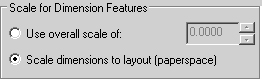
6. In the Scale for Dimension Features frame of the Fit tab, place a bullet next to Scale dimensions to layout (paperspace).


7. Pick the OK button and then the Close button to continue. (The rest of the setup has been done for you.)
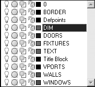
8. Set the DIM layer current.
9. Place the dimensions shown in Figure 22.1.1.1.9a. (Use grips or the Stretch command to adjust the size and shape of the viewport as necessary.)

Figure 22.1.1.1.9a10. Now place the dimensions in the round viewport as shown in Figure 22.1.1.1.10a. (Hint: You may have to use DimTedit to help you.)
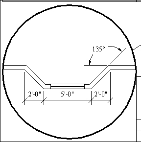
Figure 22.1.1.1.10a
11. Return to Paper Space by double-clicking outside the viewports. Alternately, you can use the MODEL toggle on the status bar.
Command: saveas
12. Save the drawing as MyFlr-pln22a, but don't exit.
As you can see, the only problem presented by dimensioning in Paper Space was one of room. But if dimensions didn't fit into the viewport, you could use standard modifying tools (grips or the Stretch command) to resize it. (Remember that the viewport exists in Paper Space. So any modifying on the viewport itself must be done there.)
Did you notice that the dimensions appeared not only in the active viewport but also in the other viewports as well? (Look in the large viewport where you can see both the bath and bay window.) This presented a problem that users of older AutoCAD releases would fix with careful manipulation of layers. Regardless of how you place dimensions, the techniques used to manipulate those layers are still quite useful today for a host of other reasons. You'll learn the how-tos of layers in Paper Space in Section 22.2, but first, let's take a look at the modern approach to Paper Space dimensioning.
22.1.2 Dimensioning and Paper Space – the New Way
Despite the name, the New Way of Paper Space dimensioning really involves no new techniques at all. With some programming adjustments, you simply place dimensions in Paper Space rather than Model Space (regardless of where the objects to be dimensioned reside). AutoCAD automatically interprets in which space the objects exist and adjusts the dimension accordingly. Using this new program, all dimensions exist in Paper Space – even if the object dimensioned exists in Model Space.
You should remember some general rules when using this new approach:
-
The Dimassoc system variable must be set to 2. Since this is the default for new drawings, you won't have a problem with them. However, if you're working with a drawing created in an earlier release, you'll have to change the variable setting.
-
The new programming may have a problem recognizing multilines. If this occurs, you'll find it necessary to either explode the multilines or use the Olde Way as detailed in Section 22.1.1.
Do This: 22.1.2.1 Adding Paper Space Dimensions – The New Way
-
Open the flr-pln22a-new.dwg file in the C:\Steps\Lesson22 folder.
-
Be sure the Dimassoc system variable is set to 2.
-
Be sure you're in Paper Space (the toggle on the status bar should read PAPER).
-
Follow these steps.
TOOLS
COMMAND SEQUENCE
STEPS

Command: dli
1. Place the dimensions indicated in Figure 22.1.2.1.1a for the upper left viewport. Do not change to Model Space except to make adjustments in the display as needed. Use grips to resize the viewport as needed.
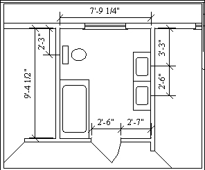
Figure 22.1.2.1.1a2. Now dimension the bay window as shown in Figure 22.1.2.1.2a. Again, don't change to Model Space except to make adjustments in the display.
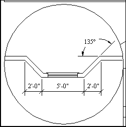
Figure 22.1.2.1.2a3. Now Zoom all and look at the drawing. Compare it to the drawing you did in the last exercise (reopen that drawing if necessary and view the two side by side).

Command: qsave
4. Save the drawing and exit.
Did you notice the difference between the two drawings?
You should have seen that the dimensions placed in the first exercise appeared both in the viewport being dimensioned and in the full viewport at right. This happens because the dimensions exist in Model Space, which appears through the viewports. In the drawing you created in the second exercise, the dimensions appear only in the viewports where you created them. These dimensions, although detailing objects that live in Model Space, exist in Paper Space.
It won't be necessary to manipulate layers to hide dimensions in the second drawing, but you'll have to do so in the first. You'll see how in our next section.
|
| < Day Day Up > |
|
EAN: 2147483647
Pages: 96