19.1 Creating Attributes
|
| < Day Day Up > |
|
What exactly is an attribute?
Think of an attribute as a vessel that carries information. This information can be AutoCAD generated or user defined. We've learned that all objects in a drawing contain information kept in the drawing's database. This information identifies the object using such things as type, style, color, linetype, layer, position, and so forth. An attribute allows you to attach this information (and other types of information) to a block and to retrieve it later.
19.1.1 Defining Attributes
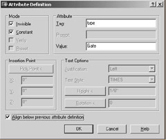
AutoCAD provides a simple, straightforward dialog box (Figure 19.1.1a) for creating attributes. Access it with the Attdef command (or the att hotkeys). Understanding this dialog box will go a long way toward helping you understand how attributes work.
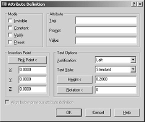
Figure 19.1.1a
Let's take a look.
-
As you can see in the upper left frame (Mode), AutoCAD provides four modes from which to choose. These control how the attributes function. By default, all modes are toggled off (the check boxes are clear). Let's see what happens when you toggle each one on.
-
An Invisible attribute holds data that won't show on the screen or drawing. This setting is ideal for vendor and pricing information. (Use visible data for information you wish to see on the drawing – such as valve sizes, window sizes, or title block data.)
-
A Constant attribute contains information that doesn't change. AutoCAD won't prompt for this information when you insert the block, and you can't edit the value of the constant attribute after inserting the block.
-
When you insert a block with an attribute that was created in Verify mode, AutoCAD will first prompt you to enter a value for the attribute and then prompt you again to verify that value.
-
You won't be prompted for any attribute values (except those requiring verification) when you create the block in the Preset mode. AutoCAD assumes default values for all the attributes when the block is inserted.
-
-
The Attribute frame provides a convenient location for you to easily place other important information.
-
Enter the name of the attribute in the Tag text box. Make this something simple but descriptive so that you or another user can easily identify it.
-
Place the prompt – what you want AutoCAD to say when asking you for a value to assign to this attribute – in the Prompt text box. Follow the advice of the old English professor: "Be brilliant; be brief." (In other words, keep your prompts short, concise, and to the point.)
-
You can place a default value for the attribute in the Value text box. AutoCAD doesn't require a default value, but it'll provide you with the ability to respond to the prompt with an enter keystroke or a right-click of the mouse.
-
-
You can identify the Insertion Point of the attribute by coordinate, or you can use the Pick Point < button to select it on the screen. When the block is inserted, the text will be placed in relation to the block as defined here.
-
In the Text Options frame, you'll use control boxes to select the Justification and Style of the attribute's text. You can also place the Height and Rotation of the text into the appropriate text box, or pick a button to select each from the screen.
-
When creating several attributes, a check in the Align below previous attribute box will help keep the attributes organized. Let's create a block with attributes.
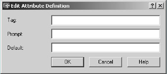
| Note | To edit or change an attribute before creating the block, use the standard text editor command (DDEdit). AutoCAD will present the dialog box shown in Figure 19.1.1b. Here you can change the Tag, Prompt, or Default value. You can't change the mode of the attribute, however. You'll have to create a new attribute for that. Remember this handy method when you have several similar attributes to create. Simply copy your attributes to the blocks you wish to create, edit them as needed, and then create the block. |
Let's create a block with attributes.
| Note | You can also access the Attdef command from the Draw pull-down menu. Follow this path: Draw – Block – Define Attributes |
Do This: 19.1.1.1 Creating Attributes
-
Open the blocks-pipe.dwg file the C:\Steps\Lesson19 folder. The drawing looks like Figure 19.1.1.1a.
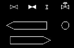
Figure 19.1.1.1a -
Follow these steps.
TOOLS
COMMAND SEQUENCE
STEPS

Command: z
1. Zoom in around the upper left valve. It looks like Figure 19.1.1.1.1a.
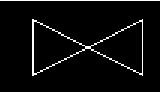
Figure 19.1.1.1.1a
2. Change the current layer to Text.
No Button Available
Command: att
3. We're going to create five attributes to attach to this valve. Enter the Attdef command by typing attdef or att at the command prompt. There is no toolbar button for this command.
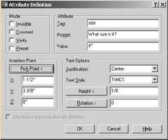
4. Fill in the dialog box as shown.
-
Accept the default modes for this block.
-
Call the attribute size.
-
The prompt should read as shown.
-
Give the attribute the default value indicated.
-
Center justify the text a snap above the center of the valve (use the Pick Point < button and set the Text Options Justification option to Center).
-
Use a text height of 1/8".
5. Pick the OK button to complete your first attribute definition. Your screen should look like Figure 19.1.1.1.5a.

Figure 19.1.1.1.5a
Command: qsav
6. Save the drawing but don't exit.
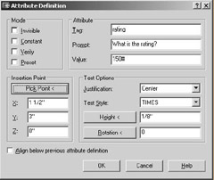
7. Repeat Steps 3 through 6 to create a Rating attribute. All the modes for the attribute should be toggled off, the tag should be rating, the prompt should read, What is the rating?, and the default attribute value should be 150#. Center the tag below the valve as seen in Figure 19.1.1.1.7a.

Figure 19.1.1.1.7aCommand: [enter]
8. Now let's create a Constant, Invisible attribute. Repeat the Attdef command.
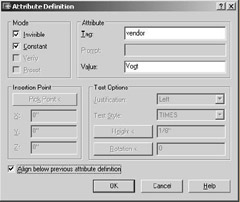
9. Create the settings shown.
-
Begin by placing checks next to Invisible and Constant. Notice that the other modes become unavailable.
-
Call the attribute vendor and give it the default value Vogt. Notice that, with a constant attribute, you don't need a prompt.
-
Place a check in the Align below previous attribute definition option. Notice that AutoCAD removes the options to locate and define text types. It assumes this information from the previous definition.

10. Pick the OK button to complete the definition.

Command: qsave
11. Save the drawing but don't exit.
12. Repeat Steps 9 through 11 to create a Type attribute.
-
Leave the modes set as they are now (creating an Invisible, Constant attribute).
-
The tag should be type.
-
The value should be Gate.
-
Place the tag beneath the vendor tag.
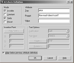
13. Create a final attribute – this one for the price of the valve.
-
Call the attribute price.
-
Have it prompt for the cost as indicated.
-
It should be invisible, but you should verify the value entered.
-
Align it below the previous attribute.

Figure 19.1.1.1.13a
Command: qsave
14. Save the drawing but don't exit.
15. WBlock the valve and the attributes to the C:\Steps\Lesson19 folder. Call it gate and use the midpoint shown in the Figure 19.1.1.1.15a as the insertion point. (Retain the objects and use Unitless as the Insert units setting.)
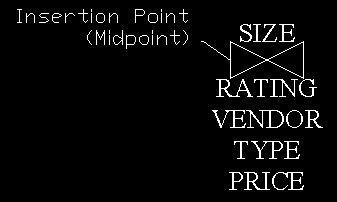
Figure 19.1.1.1.15a
Command: z
16. Zoom in around the Globe valve. It looks like Figure 19.1.1.1.16a.

Figure 19.1.1.1.16a17. Create the attributes shown in the table that follows. WBlock the valve as globe to the C:\Steps\Lesson19 folder. Use the same insertion point you used in Step 15.
MODE
TAG
I
C
V
P
PROMPT
DEFAULT VALUE
TEXT JUSTIFY
Price
Y
N
Y
N
How much does it cost?
Vendor
Y
Y
N
N
Jamesbury
Type
Y
Y
N
N
Globe
Rating
N
N
N
N
What is the rating?
150#
Centered
Size
N
N
N
N
What size is it?
3"
Centered
-
|
| < Day Day Up > |
|
EAN: 2147483647
Pages: 96
- Chapter IV How Consumers Think About Interactive Aspects of Web Advertising
- Chapter V Consumer Complaint Behavior in the Online Environment
- Chapter IX Extrinsic Plus Intrinsic Human Factors Influencing the Web Usage
- Chapter XIV Product Catalog and Shopping Cart Effective Design
- Chapter XV Customer Trust in Online Commerce