9.2 More Commands in the Change Group
9.2.1 Two Ways to Change the Length of Lines and Arcs “ The Lengthen and Stretch Commands
Prior to the inclusion of the Lengthen command, AutoCAD relied on the Stretch command to lengthen or shorten one or several lines. The Stretch command is still reliable and is really quite simple once you understand the need to use a crossing window to select objects. The command sequence is
Command: stretch (or s )
Select objects to stretch by crossing- window or crossing-polygon...
Select objects: Specify opposite corner: [note the instruction on the previous line “ select the object(s) to be stretched using a crossing window]
Select objects: [enter to confirm completion of the selection set]
Specify base point or displacement: [pick a base point]
Specify second point of displacement or <use first point as displacement>: [pick a target point]
The line instructing you to Select objects to stretch by crossing-window or crossing- polygon... is easily overlooked as it appears above the actual prompt. But don't overlook its importance. You must select objects using a crossing window (or crossing- polygon , which we'll discuss in Lesson 10). Unfortunately, AutoCAD doesn't default to a crossing window, so you must enter c (or use implied windowing) to create a crossing window for object selection.
Notice that you have the same option provided by the Copy and Move commands “ that is, you can select a Base point or displacement . To review how these work (as well as the Second point of displacement ), see the discussion in Section 7.2.1.
Let's experiment with the Stretch command.
Do This: 9.2.1.1 Stretching Objects
-
Be sure you're still in the star+ drawing in the C:\Steps\Lesson09 folder.
-
Follow these steps.
Tools
Command Sequence
Steps
Command: la
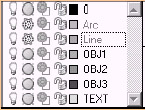
1. Be sure the Line layer is frozen.

Stretch Button
Command: s
2. Enter the Stretch command by typing stretch or s at the command prompt. Alternately, you can pick the Stretch button on the Modify toolbar.
Select objects to stretch by crossing- window or crossing-polygon...
Select objects:
Specify opposite corner: 8 found
3. Place a crossing window around the upper part of the star as indicated in Figure 9.2.1.1.3a.

Figure 9.2.1.1.3a:Select objects:
4. Hit enter to complete the selection set.
Specify base point or displacement: 0,2
5. Use the displacement option and type a displacement of 0.2.
Specify second point of displacement or <use first point as displacement>: [enter]
6. Remember, when using the displacement option, you hit enter when prompted for a second point .
Your drawing looks like Figure 9.2.1.1.6a.
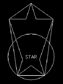
Figure 9.2.1.1.6a:
Command: u
7. Undo your changes.
Of course, AutoCAD doesn't limit you to one direction or even one object with the Stretch command. So in some ways, it still exceeds the newer Lengthen command. But the Lengthen command has its good points, too. Let's look at the command sequence:
Command: lengthen (or len )
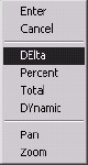
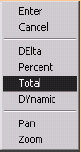
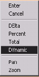
Select an object or [DElta/Percent/Total/ DYnamic]: [tell AutoCAD what you what to do with the object or select a line or arc; subsequent prompts will depend on which option you select]
Current length: X.XXXX [if you select an object, AutoCAD tells you the current length; if you select an arc, it'll tell you the included angle as well]
Select an object or [DElta/Percent/Total/ DYnamic]: [enter to complete the command]
The command includes four fairly simple options.
-
DElta (the old Greek word for "change") means change. When selected, it prompts:
Enter delta length or [Angle] <0.0000>: [enter the amount of change you wish]
Select an object to change or [Undo]: [select the object closest to the end at which you wish to add the length (use a negative number to shorten the line or arc]
If you select the Angle choice of the DElta option, you can add to an arc by specifying the angle of the arc to add.
-
Percent allows you to change the length of the selected object by percent. AutoCAD prompts:
Enter percentage length <100.0000>:
Note that 100% means no change. More than 100% increases the length of the object and less than 100% decreases the length. Length is added or removed from the end closest to where you select the object.
-
Total simply means, "How long do you want the object to be?" AutoCAD will add or remove as necessary (again, from the selected end) to make the object as long as you have specified.
-
DYnamic allows you to manually (or dynamically ) stretch the object to the desired length. AutoCAD prompts:
Select an object to change or [Undo]:
Specify new end point:
You select the object to change and specify a new end point .
Let's see what we can do with the Lengthen command.
Do This: 9.2.1.2 Using the Lengthen Command
-
Be sure you're still in the star+ drawing in the C:\Steps\Lesson09 folder.
-
Thaw the Line and Arc layers .
-
Zoom all. Notice the line and arc.
-
Follow these steps.
Tools
Command Sequence
Steps
No Button Available
Command: len
1. Enter the Lengthen command by typing lengthen or len . Unfortunately, there is no button for this command.
Select an object or [DElta/Percent/Total/ DYnamic]:
2. Select the arc.
Current length: 1.5708, included angle: 90
3. AutoCAD reports the true length of the arc and the included angle.
Select an object or [DElta/Percent/Total/ DYnamic]: de
4. Use the DElta option to change the length.
Enter delta length or [Angle] <0.0000>: 1
5. AutoCAD asks if you want to make a change by Angle or length . Since length is the default, type 1 to add one unit to the arc.
Select an object to change or [Undo]:
6. Select the upper end of the arc. AutoCAD adds one unit to the upper end. It now looks like Figure 9.2.1.2.6a.

Figure 9.2.1.2.6a:Select an object to change or [Undo]:
7. Now select the left end of the horizontal line. Notice that AutoCAD adds a piece one unit long to the end.
Select an object to change or [Undo]: [enter]
8. Hit enter to complete the command.
Command: [enter]
9. Repeat the command.
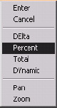
Select an object or [DElta/Percent/Total/ DYnamic]: p
10. Let's make an adjustment by the Percent method. Select the Percent option.
Enter percentage length <100.0000>: 50
11. Let's cut the objects in half. Enter 50 for the percentage length .
Select an object to change or [Undo]:
Select an object to change or [Undo]:
Select an object to change or [Undo]: [enter]
12. Select the lower end of the arc; then select the right end of the line. Hit enter to complete the command. The objects now look like Figure 9.2.1.2.12a.

Figure 9.2.1.2.12a:Command: [enter]
13. Repeat the command.
Select an object or [DElta/Percent/Total/ DYnamic]: t
14. This time we'll set the Total length of arc and line. Select the Total option.
Specify total length or [Angle] <1.0000)>: 4
15. Type 4 to set a total length of four units.
Select an object to change or [Undo]:
Select an object to change or [Undo]:
Select an object to change or [Undo]: [enter]
16. Select the left end of the arc; then select the right side of the line.
Notice that Total added to the arc but subtracted from the line.
Finally, hit enter to complete the command. The objects now look like Figure 9.2.1.2.16a.

Figure 9.2.1.2.16a:Command: [enter]
17. Repeat the command.
Select an object or [DElta/Percent/Total/ DYnamic]: dy
Select an object to change or [Undo]:
Specify new end point:
18. Using the Dynamic option, select the line and watch how it changes as you move the cursor back and forth. Then try it with the arc.
Command: quit
19. Close the drawing without saving the changes.
The greatest differences between the Lengthen and Stretch commands are twofold. First, there is an easy precision allotted by the Lengthen command; and second, the Stretch command allows you to modify more than one object at a time.
I'm more prone to use the Stretch command partly because, more often than not, I must modify multiple objects. But I use it also out of habit. For such a simple command, it's remarkably versatile and quite useful.
9.2.2 "Oh, NO! I Drew It Upside Down!" “ The Rotate Command
Okay. So this'll probably never happen to you (then again, you might just be surprised). Still, it's not unusual to find a need to rotate text for a better fit or to rotate a piece of equipment or furniture for a more efficient layout. Either way, the Rotate command offers a simple solution to problems that, on a drawing board, might cause a redraw .
The Rotate command sequence is
Command: rotate (or ro )
Current positive angle in UCS: ANGDIR=counterclockwise ANGBASE=0
Select objects: [select the object(s) to rotate]
Select objects: [hit enter to confirm the selection set]
Specify base point: [select a point around which to rotate]
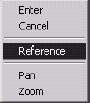
Specify rotation angle or [Reference]: [how much do you want to rotate the objects?]
-
AutoCAD begins by telling you something about the setup:
-
The Current positive angle in UCS: line refers to 3-dimensional space. You can ignore it for now.
-
ANGDIR simply reminds you that angles are measured counterclockwise (unless you changed it during the setup procedure for the drawing).
-
ANGBASE refers to a system variable that allows you to change the angle from which AutoCAD begins to measure. For example, if you tell AutoCAD to use a reference angle of 45 °, it'll add 45 to the value of the Angbase sysvar.
-
-
The default option “ Rotation angle “ simply means, "How much do you want to rotate?" Type in an angle or drag the object on the screen (use Ortho to rotate at 90 ° increments ).
-
The other option “ Reference “ prompts again:
Specify the reference angle <0>: [tell AutoCAD what the current rotation is]
Specify the new angle: [tell AutoCAD what you want the rotation to be]
Use this option when you know what the current rotation angle is and what you want it to be. If you don't know what it's but do know what you want it to be, use this option and select two points on a line that represents the current rotation. AutoCAD will determine the angle from the line you select and rotate to the new angle .
This may be confusing. Let's try an example.
Do This: 9.2.2.1 Rotating Objects
-
Be sure you're still in the star+ drawing in the C:\Steps\Lesson09 folder.
-
Freeze the Arc and Line layers.
-
Follow these steps.
Tools
Command Sequence
Steps

Rotate Button
Command: ro
1. Enter the Rotate command by typing rotate or ro . Alternately, you can pick the Rotate button on the Modify toolbar.
Current positive angle in UCS: ANGDIR=counterclockwise ANGBASE=0
Select objects:
2. Select the circle and all the objects within it.
Select objects: [enter]
3. Hit enter to confirm the selection set.
Specify base point: _cen of
4. Select the center point of the circle (use OSNAPs).
Specify rotation angle or [Reference]: 90
5. Tell AutoCAD to rotate the objects 90 °. The star will look like Figure 9.2.2.1.5a.

Figure 9.2.2.1.5a: Command: [enter]
6. Repeat the Rotate command.
Current positive angle in UCS: ANGDIR=counterclockwise ANGBASE=0
Select objects:
7. Select the circle and all the objects within it.
Select objects: [enter]
8. Hit enter to confirm the selection set.
Specify base point: _cen of
9. Select the center point of the circle.
Specify rotation angle or [Reference]: r
10. Tell AutoCAD you want to use a Reference angle.
Specify the reference angle <0>: 90
11. We rotated the objects by 90 ° in Step 5, so tell AutoCAD that the current angle (or reference angle) is 90 .
Specify the new angle:
12. Tell AutoCAD to rotate all objects to an angle of °. The star now looks like Figure 9.2.2.1.12a.

Figure 9.2.2.1.12a:
If only they were all that easy!
9.2.3 "Okay. Give Me Three Just Like It, But Different Sizes." The Scale Command
No, that doesn't mean you've to draw it two more times. Simply make two copies and then scale (or resize) the copies to meet the customer's requirements. The command sequence is one of the easy ones:
Command: scale (or sc )
Select objects: [select the object(s) to scale]
Select objects: [confirm completion of the selection set]
Specify base point: [pick the base point]
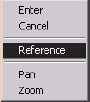
Specify scale factor or [Reference]: [enter the scale factor]
Reference works just like it did in the Rotate command. Let's see Scale in action.
Do This: 9.2.3.1 Scaling Objects
-
Be sure you're still in the star+ drawing in the C:\Steps\Lesson09 folder.
-
Be sure the Line and Arc layers are still frozen.
-
Follow these steps.
Tools
Command Sequence
Steps

Command: p
1. Use the Pan command to center the circle in the lower area of the screen.

Command: sc
2. Enter the Scale command by typing scale or sc . Alternately, you can pick the Scale button on the Modify toolbar.
Select objects:
3. Select the circle and all the objects within it.
Select objects:
4. Hit enter to confirm the selection.
Specify base point: _qua of
5. Select the bottom quadrant of the circle as the base point . Notice how the objects change as you move the cursor.
Specify scale factor or [Reference]: 2
6. Tell AutoCAD you want to scale the objects by a factor of two. The objects look the same but twice as large.
Command: [enter]
7. Repeat Steps 2 through 5.
Specify scale factor or [Reference]: r
8. Tell AutoCAD you want to use a Reference scale.
Specify reference length <1>: 2
9. We made the objects twice as large in Step 5, so tell AutoCAD the reference length is 2.
Specify new length: 1
10. Tell AutoCAD the new length should be 1 (1 where it was 2, or ½). The objects still look the same but are half the size .
Command: quit
11. Quit the drawing. Don't save your changes.