1.2 Let s Get Started
1.2 Let's Get Started
Do This: 1.2.1 Starting a Drawing Session
-
Follow these steps.
Tools
Command Sequence
Steps

The AutoCAD Shortcut
1. When you loaded AutoCAD, a shortcut that looks like the one shown here appeared on your desktop. Double-click this with your left mouse button to launch AutoCAD. AutoCAD will open fairly quickly, and you'll see the AutoCAD User Interface (the AUI) shown in Figure 1.2a (without the annotations).
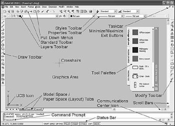
Figure 1.2.1.1a: The AutoCAD User Interface (Note: The Figure shows AutoCAD's default AUI)
Let's take a few minutes to familiarize ourselves with what we're seeing.
1.2.1 Menus and Toolbars
The folks at Autodesk ( makers of AutoCAD) made a great effort to bring AutoCAD into compliance with the standard interface conventions used by most software in the Windows environment. So if you're at all familiar with Microsoft Windows, or even with the Macintosh operating system, the interface will be familiar.
Except for some software-specific menu items, a user could almost mistake the top of the AutoCAD screen for Word, Excel, Paintbrush, or any other MS product. We find the standard title bar at the top, with three buttons on the right. These buttons will, from left to right, reduce the software to a pick on the taskbar (the gray bar across the bottom of the Windows screen), minimize or maximize the AutoCAD window (that is, make the window larger or smaller), and exit the software.
Below the title bar, we find the pull-down menu bar. This begins with the conventional Windows menus: File , Edit , and View . Take a minute to explore these and the other pull-down (or drop-down) menus. You'll notice that the AutoCAD crosshairs become a cursor (an arrow) when moved out of the graphics area. Place the cursor on one of the pull-down menus and click with the left mouse button. A menu will drop from that location showing you various options related to the selection. Picking any of these options will activate an AutoCAD macro.
One of a less apparent set of menus will appear anytime you right-click in your drawing (pick with the right mouse button). These cursor menus (or pop-up screen menus) help the user watch the screen more and spend less time searching for the right thing to press on the keyboard!
We have to give the programmers credit for accomplishing a minor miracle with the right mouse button. They have provided one of the most dynamic tools of AutoCAD. Which cursor menu appears when the right button is picked depends upon whether or not there is a command in progress, if there are items selected on the screen, and where the cursor / crosshairs are located when the button is picked!
AutoCAD provides five basic modes (or types) of cursor menus: Default, Edit-mode, Dialog-mode, Command-mode, and Other menus.
-
The Default menu appears when the user right-clicks anywhere in the graphics area if no command is active and no selection set is available (that is, nothing has been selected on the screen with which to work). Tools provided are general, frequently used commands.
Note A macro is a series of commands or events responding to a single input. Generally, you can't tell this from a single command.
-
The Edit-mode menu appears when objects have been selected on the screen, but no command has been given. The best example of this is the Grips menu discussed in a later lesson. Generally, you can expect grip-type modifying tools. But object-specific tools will appear for some objects (such as dimensions).
-
When the user right-clicks in a dialog box, AutoCAD may present the Dialog-mode menu. The tools presented will depend upon which dialog box you're using and the cursor's location when you click.
-
When the user right-clicks while there is a command in progress, AutoCAD presents a Command-mode menu with tools specific to that command.
-
The "Other menus" category includes all the other menus that don't fit easily into the first four categories. Right-clicking in different locations and at different times might present some surprising results. Feel free to experiment while you're in a drawing. Right-click over the different buttons on the status bar or over the toolbars.
We'll spend more time exploring the cursor menus as they apply to specific areas throughout this book. But for now, let's take a look at toolbars.
Below the left end of the upper menu bar, we see the first of AutoCAD's toolbars. This Standard toolbar carries many of the same buttons, or tools, found in other Windows software. Reading from the left, you see the following buttons: QNew (or New), Open , Save , Print , Plot (or Print) Preview , Publish , Cut , Copy , Paste , and so forth. To determine the function of these or other buttons on a toolbar, place you cursor over the button and wait a second. You'll see a written description appear in a cheater box.
Next to the Standard toolbar (to the right), lies the Styles toolbar. Here you can control text and dimension styles, and access the Text Style Manager and the Dimension Style Manager. We'll cover basic text in Lesson 4 and basic dimensioning in Lesson 10.
| Note | A toolbar is a group of buttons. To remove a toolbar from the screen, undock it (see below), and then pick the " X " found in the upper right corner of the undocked bar. To add a toolbar, pick the View pull-down menu and select Toolbars . You'll get a dialog box that lists all the toolbars available through the acad menu. (A quicker method would be to simply right-click on any existing toolbar, and then select the name of the desired toolbar from the menu that appears.) A docked toolbar appears "attached" to a side, top, or bottom of the graphics window. An undocked toolbar appears to float over the screen. Drawing objects may exist behind an undocked toolbar, but a docked toolbar forces the drawing to move over. To undock a toolbar, place your cursor on the two lines found on the left end (or top) of the toolbar and drag it free from its dock. (To drag an object, select it with the left mouse button, but don't release the button until you have relocated the object.) To dock a toolbar, place your cursor in the blue title bar area and drag it to a docking site (one of the borders of the graphics area). |
Moving just below the Standard toolbar, we find the Layers toolbar. Here you can quickly manipulate layers in your drawing, as well as access the Layer Manager where you'll find more detailed controls. We'll discuss layers in more detail in Lesson 6.
To the right of the Layers toolbar rests the Properties toolbar. Here you can control color , linetype, and line width.
Two other toolbars will bear considerably more attention than those at the top of the screen. The Draw toolbar, docked to the left of the drawing area, provides instant access to the most common drawing tools. The Modify toolbar, docked to the right, provides access to the most common editing tools.
Take a moment to look at each of the buttons on these last two toolbars; you'll become quite familiar with them before your AutoCAD course is finished! Once you've finished that, let's take a look at that big gray thing hovering over the right side of the graphics area “ the Tool Palettes Window.
1.2.2 The Tool Palettes Window
The Tool Palettes Window (Figure 1.2.2a) provides access to palettes that contain some of the more advanced (and useful) tools you'll discover in your basic studies “ hatch patterns and blocks. We'll go into more detail about these in due time; but for now, you might want to know what to do with this large obstruction blocking your view of the drawing area. Don't fret! You can get it out of your way! But let's examine it a bit closer first.

Figure 1.2.2a:
Looking at the left side of the palette, you'll find three tabs “ something like the tabs on file folders (in fact, the designers modeled the look after file folders).
Selecting one (placing your cursor on one and picking with your left mouse button) will bring a different set of tools to the front of the palette.
The center and largest part of the palette contains the tools made available by the palette. As I indicated earlier, we'll discuss these in some detail in later chapters.
The right side of the palette contains a scrollbar to help access the tools, and a toolbar with some useful buttons. From the top, these include:
-
the Exit button (" X ") which will close the tool palette, thus removing it from the screen and allowing you better access to the drawing (graphics) area. To reopen the tool palette, pick on the Tools pull-down menu and select Tool Palettes Window or pick the Tool Palettes button (Figure 1.2.2b) on the Standard toolbar. The palette will reappear in the location it occupied before being closed.

Figure 1.2.2b: -
an Auto-hide button (it looks like a pair of arrows and a line - <> ). Picking on this will hide the palettes, but leave the toolbar visible for easy access. To see the palettes, move your cursor over the toolbar. Pick on the button again to turn auto-hide off.
-
a Properties button at the bottom of the toolbar, which calls the menu shown in Figure 1.2.2c. Let's look at the selections available here.
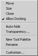
Figure 1.2.2c:-
When you select Move , AutoCAD changes the cursor to a four-sided arrow, which you can use to drag the tool palettes to a new location without docking them.
-
-
The Size selection also changes the cursor to a four- sided arrow. This one you can use to resize the palettes (from the right or bottom only).
-
Of course, Close does just that; it closes the tool palettes.
-
Selecting Allow Docking will either check or uncheck the option. When checked, the Tool Palettes Window can be docked (just like any toolbar) to a side of the drawing area. When unchecked, it can't.
-
Auto-hide is simply a menu approach to do the same thing the Auto-hide button does.
-
A really cool new tool to the 2004 release of AutoCAD is the Transparency setting for dialog boxes and tool palettes. The three dots at the end of the Transparency selection tell you that it will provide a dialog box (Figure 1.2.2d) to make your setup easier. Sliding the bar from left to right will increase the transparency level of the Tool Palettes Window, making it much easier to keep the palettes open while still being able to see the drawing below it.
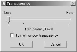
Figure 1.2.2d: -
New Tool Palette enables the user to create his or her own tool palette with job- specific items.
-
Be careful with the Rename selection. It enables the user to rename the Tool Palettes Window, not a specific tab. When you select this option, AutoCAD will provide a text box (floating over the tool palette) wherein you can rename the window. (To rename a specific folder tab, right-click over the tab and select Rename Tool Palette from the options on the cursor menu.)
-
Customize calls the customize dialog box. When called from this menu, the Tool Palettes tab will be on top. From here, you can import or export tool palettes to other AutoCAD systems, add new tool palettes, or remove existing ones.
AutoCAD's Tool Palettes Window will prove useful when we discuss blocks and hatching. For now, however, it may prove a distraction to your basic lessons. You might be better off closing it or even docking it to the right side of your screen until we're ready for it.
1.2.3 The Graphics Area
AutoCAD dedicates the largest part of the screen “ called the graphics area “ to workspace. You'll do your drawing and editing here.
| Note | AutoCAD actually uses two coordinate systems, the UCS and the World Coordinate System (WCS), but that discussion belongs in the 3-dimensional world. The UCS and the WCS are the same for the lessons in this text. |
Until the recent appearance of the tool palettes, which we'll remove from the screen during most of our work time, the only item allowed to occupy the coveted space on the graphics area was the User Coordinate System (UCS) Icon. The icon serves a very useful purpose in 3-dimensional drafting. For AutoCAD beginners in the 2-dimensional world, however, it serves as a reminder of the X- and Y-planes. (We'll discuss X- and Y-planes in more detail in Lesson 2, and the UCS Icon in more detail in our 3D AutoCAD 2004 text.) The user can disable the icon (turn it off) by entering ucsicon at the command prompt and responding off to the prompt as shown in the following sequence.
Command: ucsicon
Enter an option
[ON/OFF/All/Noorigin/ORigin/Properties] <ON>: off
Repeat the command and enter on to restore the UCS Icon. You'll learn more about AutoCAD's prompts throughout this text.
Along the right side and bottom of the graphics area, you'll find scroll bars similar to those found in most computer applications. You can use these to view or edit different areas of your drawing, but AutoCAD offers other ways that many users prefer to scroll bars. We'll discuss those as we need them.
Just below the left side of the graphics area, you'll find the Model Space /Paper Space ( Layout ) tabs. Paper Space is a more advanced tool covered later in our text. For now, will remain on the Model Space tab.
| Note | An advanced drawing environment called Paper Space enables the CAD operator to work in multiple scales on the same drawing. It is also a useful plotting tool. |
1.2.4 The Command Window and Status Bar
Just above the bottom of the screen, you can see a window with three Command prompts. Like the toolbars, this window can undock, but I don't recommend it. You can also resize it by placing your cursor on the heavy line above it, picking with the left mouse button, and "dragging" the window up or down. (The cursor will become a double arrow when properly located, and you must hold the button down for this procedure.) I usually set my command window to be large enough for two command prompts. This allows more room for drawing.
At the bottom of the screen is the status bar . On the left end of the status bar, you'll see a small box with three numbers in it. This Coordinate Display box shows the X, Y, and Z coordinates of the cursor in your drawing. We'll look again at AutoCAD's coordinate system in Lesson 2. To the right of the Coordinate Display box is a series of toggles ( Snap , Grid , Ortho , etc.). We'll look at these in some detail in Lesson 3.
On the right end of the status bar, you'll find an icon (Figure 1.2.4a) representing AutoCAD's new Communication Center.
Figure 1.2.4a:
This tool will help you keep your software up to date by informing you of any available updates. It also gives you access to articles and tips that might make your AutoCAD experience more productive, as well as general product information about new and current Autodesk products.
You'll have to set up the Communication Center if it hasn't already been done. Here's how to do that.
I can't overemphasize the importance of becoming familiar with the Command prompt. Look closely. AutoCAD speaks to you on the left side of the colon. You respond on the right. Right now, AutoCAD is "prompting" you, or asking you what you want to do. When you respond, either by keyboard entry or mouse selection, your response will appear to the right of the colon .
Once you enter a command, AutoCAD's prompt may change, asking you for more information or input. Just follow the prompts to complete your task.
Do This: 1.2.4.1 Using the Communication Center
-
If you're not already in AutoCAD, double-click the AutoCAD 2004 icon (Figure 1.2a) on the desktop.
-
Follow these steps.
Tools
Command Sequence
Steps

Communication Center Icon
[No Command Line Entries Required]
1. With your left mouse button, pick once on the Communication Center icon on the right-end of your status bar. AutoCAD will present the Communication Center dialog box (Figure 1.2.4.1a).
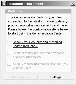
Figure 1.2.4.1.1a:2. (Refer to Figure 1.2.4.1.1a. If the dialog box looks different from this one, it may have already been set up and you can skip this exercise.) Pick anywhere on the line that reads: Specify your country and preferred update frequency . AutoCAD presents the configuration dialog box in Figure 1.2.4.1.2a.
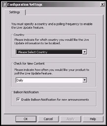
Figure 1.2.4.1.2a: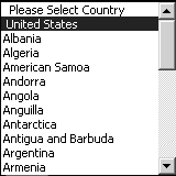
3. Pick the down arrow next to the text box that reads Please Select Country , and select a country from the drop down list. The name of the country now appears in the text box.
You can use the same procedure to change the frequency that AutoCAD will check the internet for updates in the Check for New Content frame below this one. If you have a slow connection, you might change it to check less frequently. We'll leave it set to Daily for now.
Leave the check in the Balloon Notification frame as well. This way, AutoCAD can let you know when something needs your attention.

4. Pick the Okay button to complete the setup. AutoCAD returns to the Communication Center dialog box, which now looks like Figure 1.2.4.1.4a.
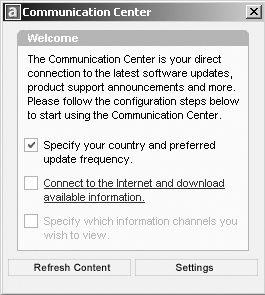
Figure 1.2.4.1.4a:5. Pick on the line that reads Connect to the Internet and download available information.
AutoCAD pauses for moment “ it may display a dialog box asking you to wait while it does the task. Then it places a check next to this line to show that it's been accomplished.
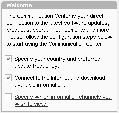
6. Pick on the line that reads Specify which information channels you wish to view.
AutoCAD returns you to the configuration settings dialog box (Figure 1.2.4.1.6a).
Most of your options are fairly clear; but if you need a hint, rest your cursor over any of the check boxes.
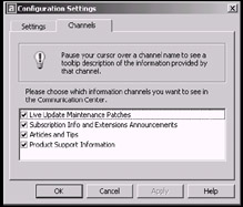
Figure 1.2.4.1.6a: 7. All of the boxes are selected by default; deselect any boxes that contain information you're not interested in, and then pick the Okay button to complete the step. AutoCAD returns to the Communication Center dialog box (Figure 1.2.4.1.7a) and will list any information that is currently available.
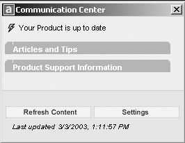
Figure 1.2.4.1.7a:
8. Review any tips or information you would like to see, and then pick the X at the right end of the title bar to exit the dialog box.
The Communication Center will automatically update its information base as often as you tell it to in Step 3, or you can manually update it by picking on Refresh Content at any time. You can also adjust all the settings you made in the previous exercise by selecting Settings at the bottom of the Communication Center.
Just to the right of the Communication Center Icon, you'll find a down arrow that calls the Status Bar Menu (Figure 1.2.4b). You'll use this menu to tell AutoCAD whether or not to display the Coordinate Display box, as well as which of the various toggles you'd like to see. We'll become more familiar with these toggles in Lesson 3.
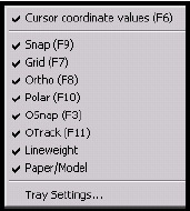
Figure 1.2.4b:
You also use the Status Bar menu to call the Tray Settings dialog box (Figure 1.2.4c). To remove the Communication Center Icon from the status bar, simply remove the check next to Display icons from services . If you leave the check here, as recommended, you can use the next check box to control whether or not AutoCAD will let you know about anything new that comes in by way of the Communication Center. When a check appears next to Display notifications from services , the Communication Center will display a bubble next to its icon whenever something needs your attention. Use the two radio buttons below this line to control how long the bubble will be displayed.
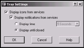
Figure 1.2.4c:
Well, you've read a lot of pages and have become familiar with the interface, but you haven't actually done any AutoCAD yet. Let's see how to set up a new drawing.
| Note | A Radio Button is a round hole. Selecting a radio button places a black dot (or bullet) inside the round hole. Radio buttons usually come in small groups, but only one button in a group can hold the bullet. |