4.3 Simple Text
Entering text into an AutoCAD drawing seems like a simple thing to do. However, it appears quite complicated. Still, once you have mastered the procedures, you'll see that text isn't so difficult after all.
The Text command allows multiple lines of text to be entered; and it shows the text on the screen as you type.
The command sequence looks deceptively simple.
Command: text (or dt )
Current text style: "Standard" Text height: 0.2000
Specify start point of text or [Justify/Style]: [pick the starting point of the text]
Specify height <0.2000>: [enter the desired text height]
Specify rotation angle of text <0>: [enter the desired rotation angle]
Enter text: [enter your text]
Enter text: [hit enter to complete the command]
Let's look at each line.
-
The first line shows the DT (for Dynamic Text) is the hotkey for Text . Note that T is also a hotkey, but for the MText command (not Text ).
Note MText is a more advanced text tool that uses a word processor format to enter text. We'll discuss it in Lesson 13. (The Text button on the Draw toolbar also calls the MText dialog box; so we'll avoid it for now.)
-
The second line provides access to more Text options than initially meet the eye.
-
The default option is Specify start point . This simply directs you to identify the insertion point of the text. You do this by coordinate input or picking a point on the screen with the mouse.
-
You don't actually have to select the Justify option (that's, you don't have to type J ) to justify your text. Typing J, however, will tell AutoCAD to present the various justification options as shown here.
Enter an option [Align/Fit/Center/ Middle/Right/TL/TC/TR/ML/MC/MR/ BL/BC/BR]:
By default, AutoCAD uses the Bottom Left option. Refer to Figure 4.3a to see where each of the options will place the text in relation to the insertion point (the "X").
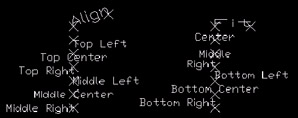
Figure 4.3a: -
The Align and Fit justifications behave in much the same manner; however, Align will adjust the text height proportionally as it fits the text between the selected points, and Fit will maintain the user -defined height.
-
The Style option enables you to choose among text styles defined within the drawing. More on this in Section 4.6, "Adding Flavor to Text with Style."
Note You can use the JustifyText command to reset the justification once the text has been entered. This command won't, however, relocate the text around the insertion point.
-
-
Set the height of the text on the next line. This is one of the places where it's easy to make a mistake. As drafters, we're accustomed to scaling our drawing but not our text. We draw 1/8" text 1/8" high. In CAD, we do just the opposite “ that's, we scale our text but not our drawing!
You'll remember from Lesson 1 that we draw full- size , and then adjust for scale when we plot (print). When we adjust to plot, we downsize our drawing to fit onto a certain size sheet of paper. Well, when we downsize the drawing, the text goes with it. So we must increase the size of the text when we create it to allow for the downsizing.
Note Something else to remember: transparent commands “ like Zoom or View “ don't work while the Text prompt is showing. This way, all the keys are available while in text mode.
Confused? It's really fairly easy to do.
Look at the Drawing Scales chart in Appendix A. The second column contains a Scale Factor. This is the key to creating the proper text size. Simply multiply the size you want the text to be when it's plotted by the Scale Factor the final plotted scale. Then you use that number as your text height.
Here is an example. I'm creating a drawing that I will plot later at 3/8"=1'-0". The factor for this scale is 32. I want my text size to be 1/8" when I plot. I multiply the 1/8 by 32 to get 4. I use 4 as my text height.
I know that may be a bit difficult to understand at this point; but believe me, it works!
Note If you make a mistake in scaling your text, don't worry. You can fix the scale easily using AutoCAD's ScaleText command. The command sequence looks like this:
Command: scaletext
Select objects: [select the text to rescale]
Select objects: [hit enter to confirm your selection]
Enter a base point option for scaling
[Existing/Left/Center/Middle/Right/TL/T C/TR/ML/MC/MR/ BL/BC/BR] <Existing>: [ generally accept the Existing insertion point unless you wish to scale from a different point]
Specify new height or [Match object/Scale factor] <0.1250>: [tell AutoCAD how large to make the text, or enter M to match the height of some existing text or S to enter a scale factor]
We'll see this command in our next exercise.
-
The next line asks for a rotation angle. This means AutoCAD wants to know if your text will be standard read-from-the-bottom-of-the-page ( left-to-right ) text or something else. Remember how AutoCAD measures angles! Read-from-the-right-side-of-the-page would be entered at 90.
-
Next AutoCAD asks for the actual text. Here you type the desired text, hitting enter for a return (like the old-fashioned typewriters). When finished, hit enter twice and the command prompt returns.
Let's try some text.
| Note | In addition to the command line, you can access the Text command by selecting Text , and then Single Line Text from the Draw pull-down menu. |
Do This: 4.3.1 Inserting Text
-
Open the pidtext drawing in the C:\Steps\Lesson04 folder.
-
For this exercise, we'll want to display the Text toolbar. Right-click on any existing toolbar and select Text from the menu that appears. Move the Text toolbar to a convenient location on your screen.
-
Refer to the drawing in Figure 4.1a as you follow these steps.
Tools
Command Sequence
Steps

Command: v
1. First let's get a bit closer. Restore the EXCHANGER view (Figure 4.3.1.1a).
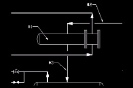
Figure 4.3.1.1a:
Single Line Text Button
Command: dt
2. We'll begin by identifying the exchanger. Enter the Text command by typing Text or dt at the command prompt. Alternately, you can pick the Single Line Text button on the Text toolbar.
Current text style: "STANDARD" Text height: 0.1250
Specify start point of text or [Justify/ Style]:
3. Pick a point near the tip of arrow #1 (Figure 4.3.1.1a). (Toggle OSNAPs Off if necessary.)
Specify height <0.1250>: .25
4. This drawing was created with no scale on a D-size sheet of paper, so we'll not have to scale the text. Assign a text height of ¼".
Specify rotation angle of text <0>: [enter]
5. Accept the default rotation angle.
Enter text: %%uE-101
6. Here is your first text trick. Lead the text with %%u to underline the text. (The %% trick calls an ASCII code. See the Text Tricks insert following this exercise for more ASCII symbols.)
Enter text: [enter]
7. Hit enter to complete the command. Notice that the text was not underlined until the command was completed.
Command: [enter]
8. Now enter a line number by arrow #2 (Figure 4.3.1.1a). Begin by repeating the command.
Current text style: "STANDARD" Text height: 0.2500
Specify start point of text or [Justify/ Style]:
9. Pick a point just above the line.
Specify height <0.2500>: [enter]
Specify rotation angle of text <0>: [enter]
10. Accept the default text height and rotation angle.
Enter text: 10"-C2-105-J51
11. Enter the line number.
Enter text: [enter]
12. Complete the command.
Command: [enter]
13. Now let's try some angled text. Repeat the command.
Current text style: "STANDARD" Text height: 0.2500
Specify start point of text or [Justify/ Style]:
14. Pick a point just to the left of the line at arrow #3 (Figure 4.3.1.1a).
Specify height <0.2500>: .125
Specify rotation angle of text <0>: 90
15. Change the text height to 1/8" and the rotation angle to 90 °.
Enter text: 8"-C2-106-J52
Enter text: [enter]
16. Enter the text and complete the command. Your drawing looks like Figure 4.3.1.16a.
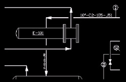
Figure 4.3.1.16a:
Scale Text Button
Command: scaletext
17. Notice that the text heights are inconsistent. Let's fix those now. Enter the ScaleText command at the command prompt. Alternately, you can pick the Scale Text button on the Text toolbar.
Select objects: [select the text]
Select objects: [enter]
18. Select the E-101 text you placed in the exchanger; then confirm the selection.
Enter a base point option for scaling
[Existing/Left/Center/Middle/Right/TL/ TC/TR/ML/MC/MR/BL/BC/BR] <Existing>: [enter]
19. Accept the default base point for scaling.
Specify new height or [Match object/Scale factor] <0.2500>: .1875
20. Tell AutoCAD to make the text 3/16" high.
Command: [enter]
21. Now let's use the Match object option to fix the line numbers . Repeat the command.
Select objects: [select the text]
Select objects: [enter]
22. Select the 10" line number (at arrow #2). We'll make it 1/8" high like the 8" line number (at arrow #3). Confirm the selection.
Enter a base point option for scaling
[Existing/Left/Center/Middle/Right/TL/ TC/TR/ML/MC/MR/BL/BC/BR] <Existing>: [enter]
23. Accept the default base point for scaling.
Specify new height or [Match object/ Scale factor] <0.1875>: m
24. Tell AutoCAD you'd like to match the height of some existing text.
Select a text object with the desired height: [select the 8" line number]
Height=0.1250
25. Select the 8" line number, which you created at a height of 1/8". Notice that AutoCAD tells you how high the text is and makes the change for you.
Command: v
26. Let's try justifying some text. Change to the PUMPS view (Figure 4.3.1.26a).
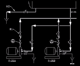
Figure 4.3.1.26a: Command: dt
27. Begin the Text command.
Current text style: "STANDARD" Text height: 0.1250
Specify start point of text or [Justify/ Style]: c
28. We don't have to go to the Justify prompt if we know what we want to do. So let's just type C for centered text.
Specify center point of text:
29. AutoCAD asks for the center point of our text. Pick a point two snaps out from the center of the valve “ near the tip of arrow #2 in Figure 4.3.1.26a. (Toggle the snap On or Off as needed.)
Specify height <0.1250>: [enter]
Specify rotation angle of text <90>: [enter]
30. Accept the defaults for Height and Rotation angle .
Enter text: 6"
Enter text: [enter]
31. Type 6" for the size of the valve. Notice that the text isn't centered as you type it.
Complete the command; the text is now centered.
32. Center some text next to the valve just below the last one. This is also a 6" valve (Figure 4.3.1.34a).
33. Using a 1/8" text height, place the text ( 2"- DR-104-D2 ) above the drain line (indicated by arrow #1 in Figure 4.3.1.26a).
34. Now center the word Drain below the funnel. This area of your drawing now looks like Figure 4.3.1.34a.
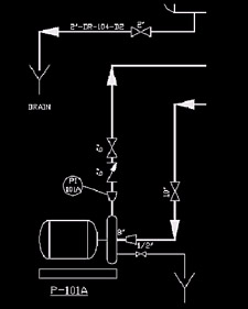
Figure 4.3.1.34a:
Command: qsave
35. Save the drawing.
Note Text Tricks
Other text tricks (based on ASCII codes) are
%%U = underlined
%%C = diameter symbol
%%P = plus / minus symbol
%%D = degrees symbolNote One of the ways CAD operators used to save regeneration time was to tell AutoCAD not to regenerate the text in a drawing. As a great portion of the drawing is text, this saved time with larger drawing files. The command they used was QText and it looked like this:
Command: qtext
Enter mode [ON/OFF] <OFF>: on
The text in the drawing was replaced with a rectangular locator (to help the operator avoid placing geometry on top of the text).
With the advent of faster computers, the QText command isn't really necessary anymore. But there is always going to be an older operator who like to QText his drawing before passing it on to a freshman operator as a joke. So if you get a drawing with QText activated, simply enter the command and turn it Off . (Remember to regen the drawing afterward.)