12.1 Many at Once - AutoCAD s Multilines and the MLine Command
12.1 Many at Once “ AutoCAD's Multilines and the MLine Command
The multiline sage began before R13. Someone created a Lisp routine that drew two lines at once. It was called DLine (for Double Line) and was enjoyed by CAD users for some time. In the piping industry, however, we needed to draw three lines at once “ the outer walls of a pipe and a centerline. So we adjusted the Lisp routine to add an additional line. I'm sure our counterparts in architecture did the same thing to add brick ledges around their houses .
All this got back to AutoCAD, and in R13 they included the MLine command. This is an easy-to-use tool designed to enhance the efficiency of multiline drawing.
The command sequence is
Command: mline (or ml )
Current settings: Justification = Top, Scale = 1.00, Style = STANDARD
Specify start point or [Justification/ Scale/STyle]: [pick the start point]
Specify next point: [pick the next point]
Specify next point or [Undo]: [either continue picking points or hit enter to complete the command]
As you can see, the actual command sequence is not very different from drawing any other line. AutoCAD prompts Specify start point and then repeats Specify next point until you've completed the line. There are, however, some simple options you must consider.
-
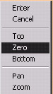
AutoCAD makes three choices available when you select the Justification option:
-
Enter justification type [Top/Zero/Bottom] <top>:
These involve where AutoCAD places the lines in relation to the user -identified point. (See Figures 12.1a, 12.1b, and 12.1c to see how they work.)
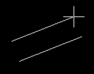
Figure 12.1a: Top Justification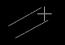
Figure 12.1b: Zero Justification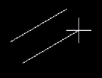
Figure 12.1c: Bottom JustificationThis may seem a bit strange , but it really does have its uses. For example, most pipe is drawn using centerlines. For a piper , then, the Zero justification would be easiest to use. But for an architect who dimensions to outer walls, the Top or Bottom justification may be just the ticket. Of course, the architect can switch to the Zero option if necessary!
-
The Scale option enables you to insert a multiline at any width. For example, a piper creates a multiline style that has three lines “ two outer walls and a centerline. The outer walls are one unit apart according to the style's definition. The piper needs a 3" diameter pipe, so he inserts the multiline at a Scale of 3.5 (the outer diameter, or OD, of the pipe). Similarly, the architect may insert a basic two-line wall at a Scale of 4 or 5.5 to cover different building materials for walls.
-
The STyle option enables you to tell AutoCAD which multiline style is needed for this particular multiline. The default is Standard , which is a basic two-line multiline with a separation of 1 unit between the lines. We'll look at creating multiline styles in Section 12.2.
Let's draw a simple multiline using the Standard style.
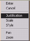
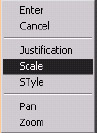
| Note | The MLine command is also available in the Draw pull-down menu. Additionally, the options are available on the cursor menu once the command has been entered. |
Do This: 12.1.1 Creating Multilines
-
Start a new drawing from scratch.
-
Follow these steps.
Tools
Command Sequence
Steps
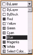
Command: col
1. Set the current color to Blue .
Command: ml
2. Enter the MLine command by typing mline or ml . (There is no button for this command.)
Current settings: Justification = Top, Scale = 1.00, Style = STANDARD
Specify start point or [Justification/ Scale/STyle]: 1,1
Specify next point: 1,6
Specify next point or [Undo]: 5,6
Specify next point or [Close/Undo]: 5,1
Specify next point or [Close/Undo]: [enter]
3. Accept the defaults and draw a simple multiline as indicated.
Your drawing looks like Figure 12.1.1.3a. Notice that the color of the multiline doesn't reflect the current color setting. This is because multiline colors are set according to the Multiline Style definition (Section 12.2).
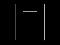
Figure 12.1.1.3a: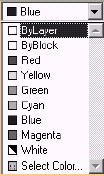
Command: col
4. Set the current color back to ByLayer .
Command: ml
5. Repeat the MLine command.
Current settings: Justification = Top, Scale = 1.00, Style = STANDARD
Specify start point or [Justification/ Scale/ STyle]: j
6. Tell AutoCAD you want to change the Justification
Enter justification type [Top/Zero/Bottom] <top>: z
7. to Zero .
Current settings: Justification = Zero, Scale = 1.00, Style = STANDARD
Specify start point or [Justification/ Scale/STyle]: 1,1
Specify next point: 1,6
Specify next point or [Undo]: 5,6
Specify next point or [Close/Undo]: 5,1
Specify next point or [Close/Undo]: [enter]
8. Repeat Step 3 using the same coordinates. You're now locating the multiline from the center. Your drawing (with both multilines) looks like Figure 12.1.1.8a.
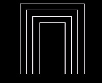
Figure 12.1.1.8a:Command: [enter]
9. Repeat the MLine command.
Current settings: Justification = Zero, Scale = 1.00, Style = STANDARD
Specify start point or [Justification/ Scale/STyle]: s
10. This time we'll change the Scale
Enter mline scale <1.00>: 2
11. to 2 .
Current settings: Justification = Zero, Scale = 2.00, Style = STANDARD
Specify start point or [Justification/ Scale/STyle]: 7,1
Specify next point: 7,5
Specify next point or [Undo]: 12,5
Specify next point or [Close/Undo]: 12,1
Specify next point or [Close/Undo]: [enter]
12. Draw the multiline as indicated. Your drawing looks like Figure 12.1.1.12a.
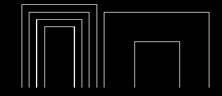
Figure 12.1.1.12a:Command: quit
13. Exit the drawing without saving.
So you see how easy it's to draw multilines. But we've only used AutoCAD's Standard style. Let's try something different. Let's define our own!