Tunneling
Tunneling
Tunneling is the concept of wrapping non-TCP/IP-compliant protocols within a protocol that can transit the public Internet. Two major tunneling protocols are prevalent today: PPTP and L2TP. A third is on the horizon, IPSec, which we will soon discuss.
The Seven-Layer OSI Model
Before continuing our discussion on tunneling, it is worth reviewing some networking basics. Figure 7.8 shows the standard seven-layer OSI (Open System Interconnection) network reference model, which we will briefly describe.
Figure 7.8. The seven-layer OSI network reference model
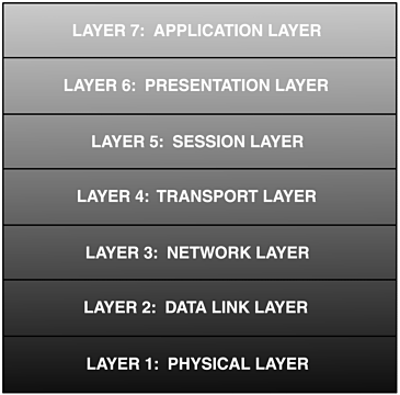
Layer 1 The Physical Layer
The physical layer (L1) is primarily concerned with transmitting raw data bits over communications medium and recovering the same raw data bits on the receiving side. This is where the determination is made of what constitutes a 1 bit and what constitutes a 0 bit. Here are examples of the communication media that can be used:
A physical wire carrying voltage, current, or frequency changes
A light carrying frequency changes or pulses
Sound or radio waves with varying frequencies
Layer 2 The Data Link Layer
The data link layer (L2) manages link setup, data exchange, and link termination. L2 is concerned with taking the raw transmission and transforming it into what appears to be an error-free transmission to the network layer. Recall that L1 merely takes bits it is given and sends them over the communications media; it has no concept of structure or the meaning of the bits. L2 frames groups of bits by adding bit patterns to the start and end of a group. This group is called a physical layer service data unit, but more commonly a frame. Specialized frames report errors, acknowledgments, and the overhead to manage a session.
Layer 3 The Network Layer
The network layer (L3) controls the interconnectivity of network computers, nodes, switches, and routers. It determines the characteristics of the computer, node, and router interface and how L3 datagrams or packets are routed within the network. L3 ensures that all packets are correctly received at their destination and determines the route the packets will take in traversing the network. This includes translating logical network addresses and names into their physical equivalents.
Layer 4 The Transport Layer
The transport layer (L4) manages the flow of data between hosts across a network. This is accomplished by splitting long data streams into smaller chunks that fit within the maximum packet size for the networking medium being used. These chunks are then encapsulated with header and ending frames, which provide sequencing and error detection/correction capabilities. L4 is a source-to-destination or end-to-end layer and is responsible for ensuring successful transmissions, including retransmission if packets arrive with errors.
Layer 5 The Session Layer
The session layer (L5) is the user's interface into the network. L5 manages session setup, data exchanges, and session termination. It provides synchronization services between tasks at each end of the session, allowing for resumption of the session at the point where an error occurred rather than requiring the entire session to be retransmitted. L5 also performs any overhead necessary to maintain the session during periods of inactivity.
Layer 6 The Presentation Layer
The presentation layer (L6) performs any data-format translation for the networked communications. It takes data in the format the application understands and translates it into a generic format that can be transmitted over the network. Data compression may also occur at this time. Received data is translated from the generic format to the format the application understands.
Layer 7 The Application Layer
The application layer (L7) allows access to network services such as networked file transfer, messaging, and remote procedure calls that support applications directly. This layer also controls general network access and portioning of tasks across the network and provides network error and status information for applications.
PPTP
The Point-to-Point-Tunneling Protocol (PPTP) is a networking technology that supports multiprotocol virtual private networks. This allows your private network to utilize IP, IPX, and NetBEUI and provides access to a wide variety of existing LAN infrastructures. PPTP is supported in nearly all the current Microsoft products because Microsoft was one of the original members of the consortium defining the standard, including specifications for Linux and other platforms.
In an effort to make PPTP a complete VPN solution, Microsoft markets PPTP with other components to provide the authentication and encryption required for a VPN. The authentication is provided in various ways, depending on the platform. In Windows NT, this is done via the Remote Access Service (RAS): the Password Authentication Protocol (PAP) and the Challenge Handshake Authentication Protocol (CHAP).
RAS utilizes a shared secret between the RAS client and the RAS server. This shared secret is in the form of a user-supplied password at the client, which is then used to derive a MD4 hash. The stored password in the Windows NT security database at the server is used to compute the same MD4 hash. Although this solves the problem of key distribution, it leaves the system vulnerable to cryptographic attacks to identify the hash value. In fact, in 1998, Counterpane Systems released a statement that five major security flaws existed with Microsoft's implementation of PPTP and several other attacks were identified that would compromise the security of the VPN. (See Chapter 6, "Cryptography," for more on cryptographic attacks.)
The important point to remember is that even though a standard or defined protocol is used, it is the implementation that truly provides the security. If the implementation is flawed, the security profile is compromised. Protocols or standards sometimes receive bad press when actually the particular implementation is to blame. Even when the implementation is performed by smart, knowledgeable groups, there can still be problems.
L2TP
The Layer Two Tunneling Protocol (L2TP), an extension to the PPP, enables ISPs to operate VPNs. PPP defines a standard for encapsulation of multiprotocol packets over L2 links, and its use in L2TP provides the flexibility to carry any routed data protocol. L2TP merges the best features of two other tunneling protocols: PTPP from Microsoft and L2F from Cisco Systems. As the name implies, the tunneling occurs at the network layer (L3), or at the data link layer.
L2TP is made up of two main components: the L2TP Access Concentrator (LAC) and the L2TP Network Server (LNS). The LAC is the device that terminates a connection or link and provides a means of access to the physical layer for communications. The LAC is also known as the network access server in Layer 2 Forwarding (L2F), a predecessor to L2TP. The LNS is the device that terminates the PPP data stream. The LNS can also be used to authenticate the data stream. It can have only a single LAN or WAN interface but can terminate calls arriving via any LAC's interface. For example, async serial, ISDN, PPP over ATM, or PPP over Frame Relay. The LNS is also known as the Home Gateway (HGW) in L2F terminology.
As with PPTP, L2TP requires the use of additional components to provide the encryption and user authentication for VPN security. Likewise, L2TP is susceptible to the same vulnerabilities as PPTP. However, under L2TP the tunneling is performed at L2, so this provides greater flexibility in what encryption protocols are used.
EAN: 2147483647
Pages: 73