Defragmentation
| | ||
| | ||
| | ||
The underlying flash technology does not allow a random range of memory within the device to be erased. Hence, when a file is deleted, it is simply marked as deleted in the header and left in the flash memory. To make the space occupied by deleted files available for reuse, the empty ranges are relocated into locations that can be erased. Figure 7.3 illustrates this defragmentation process. The heavily shaded areas represent the file headers; the lightly shaded areas represent the deleted files.
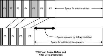
Figure 7.3: TFS Defragmentation Process.
Several different methods exist for performing the cleanup or defragmentation process. Like most other embedded systems issues, the chosen technique depends largely on the characteristics of the application environment, the available hardware, and the tradeoff between complexity vs. capability. You can certainly find more complex ways of handling defragmentation than the method used with MicroMonitor, but usually, that added complexity makes the implementation of the entire file system much more complicated. The goal here is to keep the file storage simple and linear, guaranteeing that any one file can be assumed by the application to exist in contiguous space in the flash memory. The following discussion covers two different approaches. The first is quite simple but has its flaws (which, depending on the system, might be acceptable). The second is more robust and, with a few added options, can be quite flash-friendly.
Simple but Potentially Hazardous
The easiest solution for defragmentation is to concatenate each of the non-deleted files into RAM space, erase all the flash space allocated for TFS file storage, and then copy the entire concatenation back into the flash. On the positive side, this solution is simple and eliminates the need to pre-allocate one of the flash sectors as a spare. On the negative side, this solution assumes that a block of RAM that is statically allocated for this job is as big as the flash space allocated to TFS. Worse, if the system is reset or takes a power hit during defragmentation, the file system will probably be corrupted.
More Complicated, but Much More Robust
A more practical approach is to provide a means of defragmentation that is robust enough to allow the system to reset at any point in the defragmentation process. This approach does not use a large block of RAM, but it does require that one non-volatile block of memory (at least as large as the largest sector that TFS covers) be pre-allocated to the defragmentation process. In TFS, this block of memory is the spare sector, the sector in the flash space immediately following the last sector used by TFS for file storage. Because this spare sector most likely is too small to hold a temporary copy of all active (non-deleted) files, the defragmentation process gets quite a bit more complicated. The copy must now be done in chunks instead of all at once.
While this approach is more complicated, it has the advantage of being immune to corruption as a result of a power hit or reset. This defragmentation process can be restarted at any point. The one disadvantage of this technique is that the spare sector is cycled frequently. It is the spare sector that is likely to reach the technological limit (number of erase cycles) and begin to fail. The point at which this limit is reached is very dependent on the device, the number of sectors dedicated to TFS, and the rate at which files are deleted and recreated. One major improvement to this scheme (to enhance the overall lifetime of the flash device) is to use battery- backed RAM in place of the spare sector, but, obviously, this luxury is unlikely to be approved for a budget-sensitive application.
Implementing a power-safe defragmentation is no cakewalk . This part was by far the toughest piece of code to implement for MicroMonitor. The defragmentation process uses three different pieces of flash space:
-
The spare sector, which has already been pre-allocated.
-
The defragmentation state table, which contains two 32-bit CRCs for each sector used by TFS for file storage. This information allows an interrupted defragmentation process to determine, after it has restarted, what sector it was processing when it was interrupted .
-
The post-defragmentation header table, which is a table of the headers of all the files that are to survive the defragmentation (all the non-deleted files). The post-defragmentation header is a table of header structures similar to the header structure discussed above. These headers are used with the defragmentation state table to restart an interrupted defragmentation.
| | ||
| | ||
| | ||
EAN: 2147483647
Pages: 118