10.4 The (diminishing) role of test equipment
|
10.4 The (diminishing) role of test equipment
Regardless of how test list selection is performed or whether only defects should be targeted as opposed to specification testing, the ability to deliver signals reliably to the DUT has never been under such scrutiny as it is right now. The physical limits of interconnects between instrument and DUT and the disparate nature of DUT and instrument result in serious difficulties in modern-day test arrangements, whether on validation benches or on production floors. This section describes the architecture and operation of test equipment as well as some of the challenges they face in the context of high-frequency analogue testing such as in the case of wireless communications devices.
Modern test instruments almost invariably rely on powerful DSP techniques in order to facilitate automation [21] and to enhance measurement accuracy and repeatability. As was mentioned in Section 10.2, using DSP techniques, a DUT response signal is measured by first digitising it using a highly accurate analogue-to-digital (A/D) converter. Subsequently, microprocessor based computations are performed in order to analyse the digitised signals. For example, in a spectrum analyser, a block diagram of which is illustrated in Figure 10.3a, hardware or software implementations of a Fast Fourier Transform (FFT) are utilised before displaying the results to a user monitor. As one proceeds to higher test signal frequencies, an extension to the diagram of Figure 10.3a is required as shown in Figure 10.3b. In such an extension, the high-frequency signal is first transported to a lower frequency by passing it through a mixer that is driven by a spectrally pure local oscillator (LO). The lower frequency is chosen to fall within the range that the A/D converter can tolerate without compromising accuracy. Moving a bit higher in frequency, further modifications to the basic block diagram of Figure 10.3a are necessary. Specifically, at sufficiently high frequencies, wave propagation phenomena across interconnections between instrument and DUT have to be considered, and since perfectly matching input and output impedances across all frequencies is generally impossible, it becomes imperative to evaluate signal losses due to reflections at the pertinent interfaces. To perform such tests, directional couplers are incorporated in network analysers in order to separate incident and reflected waves at a given port [21]. Network analysers are currently indispensable in the test and characterisation of large-volume radio-frequency (RF) ICs.
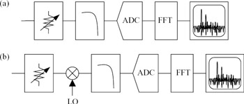
Figure 10.3: (a) A DSP-based spectrum analyser. (b) Similar spectrum analyser capable of characterising higher-frequency signals by shifting them down to the frequency range of the ADC
While providing extremely high reliability and programmability, the above DSP-based instruments are still relatively cumbersome to automate because of size and cost issues. They have thus remained on the validation and characterisation bench. Historically, the path to the interconnection and synchronisation of a multitude of equipment for production floors evolved into building automatic test equipment (ATE). Specifically, many of the underlying test-specific components (and computations) of bench instruments are replaced in ATE by centralized processing, synchronisation, and control. A single programming language and syntax are used for seamlessly operating the various instruments. The actual ‘measurement’ portions of the hardware described in Figure 10.3 are also built into the ATE using off-the-shelf components. Figure 10.4 shows a functional diagram of a typical mixed-signal automatic tester [21]. As can be seen, the other main difference to note from bench equipment is in signal handling. Due to the need for automation and general-purpose functionality, a significant effort goes into providing efficient signal handling mechanisms. A more detailed description of the generic architecture of ATE and its limitations as well as a description of signal handling are both described in the following subsections.
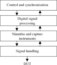
Figure 10.4: ATE integration of DSP-based measurement instruments. Central processing and control are used, and an automatic signal handling mechanism is incorporated
10.4.1 Generic architecture of automatic test equipment
A more detailed view of a mixed-signal automatic tester is shown in Figure 10.5. It includes various sources and meters, an extensive relay matrix, clock and synchronisation sources, timing measurement devices, and a digital subsystem for digital test vector formatting, comparison and manipulation. In order to remain a general-purpose instrument, a mixed-signal tester relies on a few components, such as arbitrary wave-form generators and digitisers, and flexible DSP techniques that can cover many tests and span different DUT specifications. In general, the analogue components in the above architecture are the critical ones since they potentially operate on low-level signals and since their function (whether sourcing or capturing) is altered by the physical interaction with whatever is connected to their interface terminals.
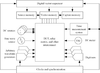
Figure 10.5: Block diagram of a generic mixed-signal automatic tester [6]
When more analogue channels need to be tested on the same platform, more of the specialised analogue instruments (arbitrary waveform generators and digitisers) are in corporated with in the test system. This is one of the cost drivers for RFATE, since the analogue instruments themselves are costly. Moreover, the new instruments have to be synchronised with the digital components of the tester, powered up and cooled adequately, and seamlessly incorporated into the tester's software environment. Such difficulties have meant that a limited number of instruments could be incorporated into a tester platform, which in turn means that a limited amount of test parallelism can be exploited to maximise test throughput during production. Typically, only two or four analogue channels are tested simultaneously on a single ATE during production.
10.4.2 Signal delivery
The portion of the ATE generally responsible for signal delivery is the test head, and it is where components like directional couplers, pin electronics and DUT-related power supplies are found. Also on the test head is a device interface board (DIB), which is a multilayer printed circuit board (PCB) responsible for implementing the final connection between instruments internal to the ATE and the DUT. The greatest difficulty in the initial phases of production testing is usually in ensuring that the DIB behaves in a manner that closely mimics conditions used during device characterisation [6]. The reason is that the test engineer, not the ATE vendor, is usually responsible for the design of this board. Moreover, instrument performance specifications provided by the ATE documentation do not generally assume signal delivery through the DIB. It is the responsibility of the DIB designer and/or test engineer to ensure that the measurement specifications are met even as the signals propagate through the DIB. This is a task that is easier said than done. The primary reason is that signal integrity analysis (with full field solvers) is generally difficult. Instead, DIB design relies on experience, prototyping, and rules of thumb. Some attempts have been made to provide simulation tools for the DIB or the complete signal paths from the pin electronics to the DUT. A good example of this is the approach described in Reference 22. In this approach, the problem is simplified by tackling each of the connectors, sockets, cables, contactors and PCB traces separately. Moreover, a combination of measurement techniques such as time-domain reflectometry and simulation techniques using field solvers is employed.
|
EAN: 2147483647
Pages: 100