Lay of the LAN : Cabling Basics
| |
Lay of the LANCabling Basics
If you're on a network, your machine has to be connected to at least one other machine, whether through metal cabling, fiber- optic light guides, or radio waves. Even as new technologies, such as radio wave-based networks and infrared light-based networks, produce new ways for connecting nodes to each other, the least expensive and most popular medium for networking computers is still copper wire.
Networks based on copper cabling generally use one of two main cable types: coaxial or twisted-pair. ARCnet started with RG-62/U and RG-59/U coaxial cable, but now includes twisted-pair and even fiber-optic cabling. Likewise, Ethernet, which was defined in the IEEE 802.3 standard, was originally implemented only on thick coaxial baseband cabling. But the Ethernet standard has expanded to include broadband coaxial, fiber-optic cabling, and twisted-pair.
Ethernet Cabling
The thick Ethernet cabling standard was designed to serve as a network backbone. In this design, machines are connected to a thick, 0.4-inch double- shielded coaxial segment, or bus, through transceiver cables, using 15-pin transceiver or AUI cables. Each AUI cable can be up to 50 meters longwhich is a blessing given the difficulty of maneuvering the thick, trunk cabling.
The thick Ethernet cabling system has been standardized by the IEEE as 10Base5. The "10" in 10Base5 refers to its 10Mbit/sec transmission rate, while the term "Base" refers to baseband cabling and the "5" refers to the maximum length for a segment in hundreds of meters. The coaxial transceivers are connected directly into the coaxial trunk either by piercing the cabling (called a vampire tap, appropriately enough) or by in-line connection with N connectors. From there, an AUI cable connects each transceiver to a network interface card on a node. Each end of the 10Base5 segment must have a 50-Ohm terminating resistor installed, and only one terminator should be grounded.
Ethernet Slims Down
10Base2, also known as thin Ethernetor in slang as cheapernet, was developed to lower the cost of installing an Ethernet network. In fact, this thin coaxial cabling can still be the most cost-effective solution for companies that want to connect a few PCs within a relatively small area.
However, with 10Base2, the Ethernet bus connects directly to a T connector on the back of each node. Consequently, the design is much more prone to disaster: If any user breaks the chain (for example, by accidentally disconnecting the wrong part of the T connector), either the entire network will go down or, at the very least, the side of the network that doesn't have a server will be isolated.
The 10Base2 standard has a 10Mbit/sec transmission speed and it uses thin, flexible RG-58A/U coaxial cable, typically 0.2 inches in diameter, with a stranded conductor. Like 10Base5, the coaxial bus must be terminated at each end, and one end must be grounded. The maximum length of a 10Base2 segment is 185 meters, which is not the 200 meter limit you might expect based on its name .
With A Twist
Partly in response to complaints about the difficulty of troubleshooting coaxial Ethernet and partly to take advantage of the existing wiring in many offices, the 10BaseT standard was developed to work with Category 3 twisted-pair copper cabling. (The "T" in 10BaseT stands for twisted pair.)
Common in newer buildings , Category 3 cabling is often used as phone wiring. But because it has low noise and crosstalk characteristics, it can be used to support a network installation that can deliver 10Mbit/sec performance.
In some older buildings, the cabling may not be up to Category 3 specifications, and subsequently, may not be able to support a network installation. In this situation, you may still want to install twisted-pair cabling rather than coaxial despite its higher price, because it has an easier installation.
The 10BaseT specification calls for unshielded twisted-pair cabling, commonly called UTP, to use two of the four pairs of conductors in a typical Category 3 cable (see Figure 1). One pair transmits data, while the other is meant to receive data. The standard doesn't specify exactly what the remaining two pairs of conductors can be used for, so many cable installers use them to create a second 10BaseT data connection. However, this practice may complicate future conversion to faster transmission speeds, because the standards for 100Mbit/sec transmission over Category 3 cabling require the use of all four pairs of cable.
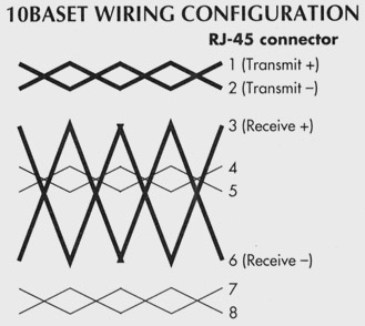
Figure 1: UTP cabling typically has four pairs of wire in one sheath, which connects to an RJ-45 modular jack. For 10BaseT, only the 1-2 pair and the 3-6 pair are wired, but not used with Ethernet.
Unlike 10Base2 and 10Base5, 10BaseT uses a star topology in which each node connects to a central concentrator or multiport repeater, which is typically located in a central equipment room or wiring closet. This topology meshes well with the existing cabling layout in most buildings.
Fast Ethernet Cabling
With many users outgrowing the 10Mbit/sec data rate of 10BaseT, vendors are responding with new products and standards to wring more speed from copper cabling. Two physical cabling strategies are emerging: using all four pairs of conductors in existing Category 3 cabling, or using two pairs of conductors in the faster and more noise resistant Category 5 cabling. Category 5 specifications permit signaling rates of up to 100MHz, compared to Category 3, which allows rates of up to 16MHz.
Two emerging standards, 100BaseTX and 100BaseT4, conform to the IEEE 802.3 standard, while a third, 100VG-AnyLAN conforms to the new IEEE 802.12.
Token Ring Cabling
Based on a token-passing logical ring topology, Token Ring networks tend to show predictable performance degradation curves when under heavy loads, as opposed to Ethernet networks, which degrade less predictably when stressed.
Although it's based on a logical ring topology, a Token Ring network looks more like a star, with each node connected directly to a central MAU. Think of this cabling arrangement as being a collapsed star, in which the middle of each segment of the ring has been pulled back to the central hub (see Figure 2). The internal circuitry of the MAU is configured as a ring. As a node is inserted into the ring and activated, a relay in the MAU closes to include the node (called a lobe) in the electrical ring.
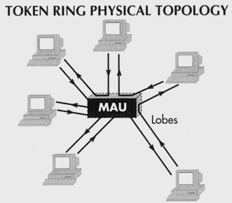
Figure 2: In Token Ring networks, packets are forwarded from station until they arrive at the correct address. Although Token Ring uses a star configuration, each station is still connected, via the MAU, to the next station on the ring.
Token Ring networks come in two "flavors": 4Mbit/sec and 16Mbit/sec. Telephone-grade UTP cabling can be used for 4Mbit/sec Token Ring equipment. IBM calls this cabling Type 3, and it is roughly equivalent to Category 2 cabling. Connecting a 4Mbit/sec Token Ring adapter to Type 3 cabling requires a media filter to reduce electrical noise. Like 10BaseT, Token Ring networks use two pairs of conductors, but in a different configuration (see Figure 3).
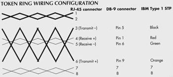
Figure 3: Token Ring initially used IBM Type 1 STP wiring. Now it typically uses a 9-pin D-subminiature (DB-9) connector, although it also has been implemented over UTP using RJ-45 connectors. As shown, wiring configurations depend on which type of cabling you're using.
IBM Type 1 cabling is required for 16Mbit/sec Token Ring networks. This requires the same wiring configuration as UTP cabling, but with solid, thicker, and heavier conductors. Each pair of wires is shielded with foil, and the resulting four-pair cable is further protected with braided shielding. IBM developed special hermaphroditic connectors to allow Type 1 cables to attach to either workstation patch cords or to other Type 1 cables as extensions.
Plan For Success
Whether you're using Token Ring or Ethernet, or if you're just starting to network your company, the cabling you choose and how you install it can make a big impact on network performance. So take the time to carefully plan your wiring layout. For example, make sure your cable distances don't exceed the recommended standard length, and double-check the cabling and connections to ensure they meet established specifications.
Such steps can do more than make your network faster and more reliable; they can free you from the chore of constantly reacting to problems caused by the physical wiring plant, which are generally hard to trace. Additionally, if you plan right, you can use the same wiring when you upgrade to a faster network, saving your company money.
This tutorial, number 80, written by Dave Fogle, was originally published in the April 1995 issue of LAN Magazine/Network Magazine.
| |
EAN: 2147483647
Pages: 193
- Chapter VI Web Site Quality and Usability in E-Commerce
- Chapter VII Objective and Perceived Complexity and Their Impacts on Internet Communication
- Chapter VIII Personalization Systems and Their Deployment as Web Site Interface Design Decisions
- Chapter XI User Satisfaction with Web Portals: An Empirical Study
- Chapter XVII Internet Markets and E-Loyalty