5.12 G.hs Start-UpClear-Down Procedures
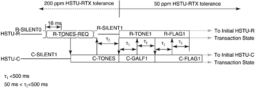
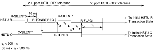
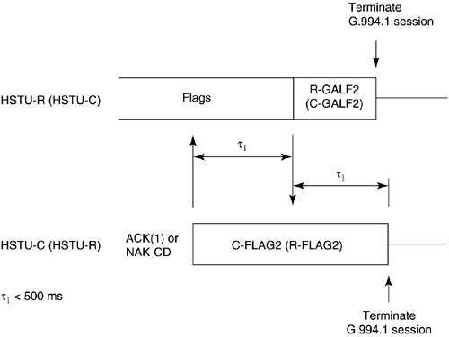
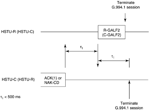
5.12 G.hs Start-Up/ Clear-Down ProceduresFinally, this section describes the start-up and clear-down procedures of a handshake session. In G.994.1, there are two types of start-up procedures: duplex and half-duplex start-up modes. Typically, the duplex start-up mode is used by ADSL transceivers, and the half-duplex start-up is used by SHDSL transceivers. Either the CO unit or the CP unit may initiate either type of start-up. Manufacturers of DSL modems are generally encouraged to support both modes of operation to provide interoperable handshake communication with other types of DSL equipment. The following subsections describe the duplex and half-duplex start-up procedures and the clear-down procedure as defined in G.994.1. 5.12.1 Duplex Start-up ProceduresAs mentioned, the customer premises unit or central office may initiate duplex start-up. The sequences of each initiation are described below. Customer Premises Initiated Duplex Start-upFigure 5.8 shows the CP initiated duplex start-up sequence. The sequence begins with the CP unit (labeled HSTU-R) transmitting the R-TONES-REQ signal, which is the transmission of phase reversals every 16 ms in one or both of its signaling families. When the central office unit detects R-TONES-REQ, it responds with signal transmission (C-TONES) on one or both of its signaling families. When the CP unit detects C-TONES for a minimum of 50 ms, it transmits silence (R-SILENT) on the line for a minimum of 50 ms and a maximum of 500 ms, and then follows with a signal transmission (R-TONE1) on one or both of its signaling families. When the CO unit detects R-TONE1, it responds to the transmission of octet value 81 16 , which is the one's complement of the HDLC Flag octet, on the modulated carriers (C-GALF1). The CP unit then responds with the transmission of HDLC flags on modulated carriers (R-FLAG1). Once the CO unit detects R-FLAG1, it responds by sending C-FLAG1 on its carrier(s) and then the units proceed to the initial transaction state of the handshake session. The timer values are shown in the figure. Figure 5.8. Customer premises initiated duplex start-up sequence (Figure 14/G.994.1[1]). Central Office Initiated Duplex Start-upFigure 5.9 shows the CO initiated duplex start-up sequence. Initially both units are in start-up. In the CO initiated mode, the CO unit starts by sending C-TONES on its carriers. When the CP unit detects C-TONES, it transmits R-TONE1 on its carriers. The remaining sequence is the same as those CP initiated duplex start-up in Figure 5.8 from the R-TONE1 phase onward. The timer values are shown in the figure. Figure 5.9. CO unit initiated duplex start-up (Figure 15/G.994.1[1]). 5.12.2 Half-Duplex Start-upAs with the duplex mode, the customer premises unit or central office may initiate half-duplex start-up. The sequences of each initiation are described below. Customer Premises InitiatedFigure 5.10 shows the CP initiated half-duplex start-up sequence. This sequence is the same as the CP-initiated duplex sequence up to the transmission of C-TONES by the CO unit and the transmission of R-FLAG1 by the CP unit. Transition to the initial transaction state begins after the completion of C-TONES in the CO unit and R-FLAG1 in the CP unit. The timer values are shown in the figure. Figure 5.10. CP initiated half-duplex start-up sequence (Figure 16/G.994.1[1]). Central Office InitiatedCO-initiated half-duplex start-up is derived from the CP initiated half-duplex start-up by eliminating the R-TONES-REQ and R-SILENT1 phases. The CP unit enters the initial transaction state upon completion of the R-FLAG1 transmission; the CO unit enters the initial transaction state upon completion of C-TONES. The timer values are provided in Figure 5.11. Figure 5.11. CO initiated half-duplex start-up sequence (Figure 17/G.994.1[1]). 5.12.3 Clear-down ProcedureFigure 5.12 shows the clear-down procedure for duplex mode. Either the CO or CP unit may initiate the clear-down procedure. The clear-down procedure is initiated by the unit that receives an ACK(1) after an MS message or a NAK-CD message: it transmits FLAGS for a period of less than 500 ms and then transmits four octets of GALF (referred to as R- or C-GALF2 in Figure 5.12) followed by silence. The unit that initiated the ACK(1) or NAK-CD message transmits C/R-FLAG2; the same unit continues to transmit the C/R-FLAG2 after it detects R/C-FLAG2 from the other unit for a period not to exceed 500 ms. Figure 5.12. Duplex clear-down sequence (Figure 18/G.994.1[1]). Figure 5.13 shows the half-duplex clear-down sequence, which may be initiated by either the CO or CO unit. Half-duplex clear-down begins with the unit that transmits ACK(1) from an MS message or a NAK-CD entering the silent state. Figure 5.13. Half-duplex clear-down sequence (Figure 19/G.994.1[1]). The other end detects the silent state for a maximum of 500 ms and then transmits four octets of R/C-GALF2, followed by silence. |
| Top |
EAN: 2147483647
Pages: 154
- Chapter II Information Search on the Internet: A Causal Model
- Chapter V Consumer Complaint Behavior in the Online Environment
- Chapter VII Objective and Perceived Complexity and Their Impacts on Internet Communication
- Chapter XIV Product Catalog and Shopping Cart Effective Design
- Chapter XVIII Web Systems Design, Litigation, and Online Consumer Behavior


