5.3 G.hs Frame Structure
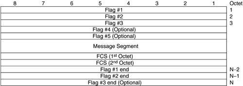
| Now that the set of messages and commands are defined, the next step is to describe the format in which the messages and commands are transmitted. A message is defined by a sequence of octets, where each message may contain one or more segments. The packets transmitted during a handshake session contain message segments. Figure 5.3 shows the frame structure of the message segment to be transmitted. The beginning of a frame is identified using the HDLC Flag octet (01111110 2 = 7E 16 ) using a minimum of three flag octets or up to a maximum of five flag octets. The end of a frame is identified with a minimum of two flag octets or a maximum of three flag octets. Following the beginning flags is the message segment. The frame check sequence (FCS) field occupies two octets; this field provides a check on the received data to see if any errors were received. If any errors were detected in the received signal, then a retransmission is required. Figure 5.3. Message segment frame structure. The octet convention is as follows . The bits are numbered horizontally 1 to 8 as shown in Figure 5.3, where bit 1 is the least significant bit ( LSB ) and bit 8 is the most significant bit ( MSB ). The octets are numbered vertically from 1 to N, which is also shown in Figure 5.3. Octets are transmitted in ascending order with the LSB sent first. In general, bit 8 in any octet is the MSB, and bit 1 is the LSB. If the field spans more than one octet, then the order of the bit values increases with decreasing octet numbers per the octet numbering convention in Figure 5.3. This is shown in the following table:
In Figure 5.3 the FCS field is shown to occupy two octets. For the FCS field, the MSB resides in bit 1 of the first octet, and the LSB resides in bit 8 of the second octet. The convention for the FCS field is opposite to the general convention for octets as described earlier. The FCS field is 16 bits, and uses the CRC-16 as defined in ISO/IEC 3309. Once the FCS field is computed, the entire frame is examined for occurrence of the following special characters : the HDLC flag sequence character 7E 16 and the control escape character 7D 16 . G.994.1 uses the HDLC byte stuffing mechanism to obtain octet transparency, which is also defined in ISO/IEC 3309. Any octet equal to flag sequence character or control escape character is replaced by a sequence of two octets as follows:
When receiving the message segment frame, the control escape octets (7D 16 ) must be removed, and the original sequence restored prior to computation of the received FCS. The FCS of the received signal is compared with that transmitted in the message segment. If the two match, then no errors were detected; if the two do not match, then there were errors received, and the message segment must be retransmitted. |
| Top |
EAN: 2147483647
Pages: 154
