Introducing AToM
| AToM stands for Any Transport over MPLS. The name comes from the ability of AToM to transport any frames over an MPLS network using MPLS as an encap and LDP as a signaling mechanism. AToM is a basic building block of Layer 2 VPNs over MPLS in Cisco. This is a Cisco term and not an industry term. The industry refers to this as pseudowires. We will also refer to this as pseudowires in the subsequent sections of this chapter and in the rest of the book. The development of AToM came about in an interesting manner.
Moving down the layers of the taxonomy diagram in Figure 4-2, you can see that pseudowires can be used to deliver two types of services to end users: virtual private wire service (VPWS) and virtual private LAN service (VPLS). VPWS includes the ability to deliver a point-to-point wire connecting the end customer devices (routers). The customer is responsible for managing the IP routing, and the provider delivers the equivalent of a leased line. The VPWS can have either the same transport type at each end (like-to-like) or any transport type at each end (any-to-any). In the case of disparate transport types, the interworking must be done at the PEs to translate the Layer 2 frames from one transport type to another. Pseudowire Systems ArchitectureLet us consider an example of Frame Relay over MPLS and see how it works in detail. Consider a Frame Relay VC being delivered to end customers. The series of configurations needed on the network elements to deliver the VC are shown in Figure 4-4. Figure 4-4. Frame Relay over MPLSTechnical Overview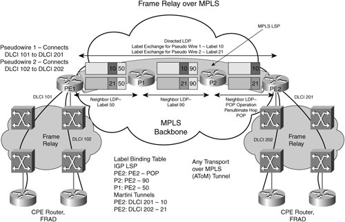 Assuming an operational MPLS network, the IGP LSPs are established using MPLS LDP. P2 advertises Label 90 for destination PE2, P1 advertises label 50 for destination PE2, and PE2 advertises a POP operation to its neighbors for destination PE2. The LSP from PE1 to PE2 has the labels 50, 90, POP from PE1 to PE2 via P1 and P2. This label sequence represents a label switched path. At this point, a live MPLS network has been set up with LDP signaling. Now consider two attachment circuits on the left side of Figure 4-4. The two DLCIs are DLCI 101 and DLCI 201. They need to be switched to the customer sites at the far end as DLCI 201 and DLCI 202, respectively. On PE1, the following configuration is required:
On PE2, the following configuration is required:
Upon configuration of the two PEs, the PEs then initiate signaling to set up the pseudowire. PE1 signals using directed LDP to PE2 and exchanges the VC type, and other parameters as part of LDP forwarding equivalence class (FEC). PE2 assigns a label of 10 for pseudowire 1 and label 21 for pseudowire 2. Now both PEs populate their forwarding tables with the label information as shown in the Figure 4-4. Note that the knowledge of pseudowires is only between PE1 and PE2. P1 and P2 routers in the core do not have any knowledge of the pseudowire labels. They know only about the IGP LSP or how to reach PE1 and PE2 via MPLS LSPs. However, when P routers load-balance traffic, they look at the payload. In L2 service, the payload is a non-IP packet; hence, the P routers in this case load-balance traffic based on the pseudowire label. Packet ForwardingWhen the setup is complete, the frames can be forwarded. Frame Relay frames now are received on the PE1. After the frame received on DLCI 101 is received, the header is stripped and a control word is added. (Refer to the IETF RFC 3985, RFC 4385, RFC 4447, and RFC 4448.) The control word is 4 bytes. It is used to carry the length of the frame, L2 flags, and a sequence number of the frame for sequence-sensitive applications. In the case of Frame Relay, the control word carries the following bits: Frame Relay forward explicit congestion notification (FECN), backward explicit congestion notification (BECN), discard eligible (DE), and command/response (C/R). The label assigned to the pseudowire is imposed; in this case it is label 10. Similarly, for the frame received on DLCI 102, the label 21 is imposed. The frames (now MPLS packets) need to be forwarded to PE2. The IGP LSP toward PE2 had the label 50 assigned by P1. The PE1 now imposes another label of 50 onto the MPLS packet and forwards it toward P1. The P1, core router, forwards the MPLS frame to P2 on its LSP by swapping label 50 with label 90. P2 does the same and forwards it to the destination. Because the advertised operation by PE2, which is the next hop from P2, was a POP operation, P2 strips the outer label and forwards the pseudowire packet to PE2 as the destination. PE2 looks up the pseudowire label, recognizes that label 10 matches DLCI 201, removes the label, attaches the frame relay header, and forwards the payload on Frame Relay DLCI 201 toward the destination. Similarly for DLCI 202, the PE2 recognizes the label 21 and forwards it appropriately. So, using labels as demultiplexers, Layer 2 frames can be forwarded to the destination across a packet network. This concept can be easily extended to all other transport types, including Ethernet VLANs (in which the pseudowire labels designate VLAN information), PPP sessions, HDLC links, ATM VPI/VCI, and ATM AAL5 frames. In some L2 transports, specialized frames or cells can be used for a management function called operations, administration, and maintenance (OAM). These OAM cells or packets can also be transported or mapped to pseudowire messages. More details of OAM are discussed in Chapter 12, "Network Management and Provisioning." Layer 2 Transport Types (Like-to-Like)This is the most commonly used L2 service. As mentioned earlier, like-to-like transport implies the same transport type exists at each end of the connection. The two attachment circuits that consist of the end-to-end connection (in this case AC1 and AC2DLCI 101 and DLCI 201) have the same characteristics. They have the same frame types, encapsulation, and QoS characteristics (including, but not limited to, committed rates, burst sizes, delay, and characteristics). There must be no change in the L2 header information except the DLCI, VPI/VCI, VLAN ID, or PPP session value and TTL (if any). This is similar to a classic Layer 2 service delivered using Layer 2 switches, except here it is delivered using an IP/MPLS infrastructure. The challenge in this type of service is delivering the same service characteristics that are similar to, if the not the same as, a traditional Layer 2 service. Let us discuss each of those services in some detail. Ethernet ServiceEthernet service today is delivered using an optical long-haul infrastructure and Ethernet switches. The cost of this type of infrastructure can be very high depending on the availability of fiber, optical gear, optical switching, and termination equipment, although the Ethernet switches themselves are cheap. In delivering Ethernet service using IP/MPLS infrastructure, the cost can be significantly reduced per Ethernet connection. Refer to the "Benefits of L2 VPNs" section for details. With Ethernet over MPLS, several services are possible, including a 10 Mbps Ethernet service, a subrate Ethernet service (for example, a 2 Mbps Ethernet service), and a VLAN service. The service is delivered on a dedicated 10 Mbps port, but it is rate limited or policed to a 2 Mbps Ethernet connection. Another example is a flexible rate service, also called a bursting rate service. In this type of service an Ethernet service is sold and billed according to usage. Alternatively, a user can sign up for an on-demand bandwidth service by scheduling via a web portal and requesting bandwidth during a certain anticipated period of usage. Link Layer ServiceSimilarly, PPP or HDLC over MPLS can be used to deliver a virtual leased line service with PPP or HDLC encapsulation, respectively. A leased line service is characterized by a data rate (the rate at which the line is clocked by the TDM network, such as 56 Kbps, T1, E1, or T3 service) and is usually an unprotected circuit. There is no buffering and no protection against failures, and it is a bit-timed connection. This can be easily emulated on the packet network. In addition to providing bandwidth guarantees, this service can be improvised by providing additional protection using MPLS fast reroute and MPLS traffic engineering. (MPLS traffic engineering is described in Chapter 8, "Traffic Engineering.") Packet buffering provides some buffering protection, especially for User Datagram Protocol (UDP) traffic. One can argue that there are situations in which buffering can hurt some types of services. However, for pure data services, buffering can also help you recover from unexpected packet loss. Frame Relay ServiceUnlike Point-to-Point Ethernet and PPP/HDLC services, the Frame Relay service is a little different when delivered over a packet infrastructure. Although you can carry Layer 2 parameters across the pseudowire such that the attachment circuits can be easily policed and updated, the QoS of the service delivered is a function of hardware and software features. Frame Relay requires delivery of in-order packets and notification of congestion information forward and backward using the FECN and BECN bits. Moreover, if the frame is out of contract based on the burst size or peak information rate, the network element might have to set the DE bit so that a switch/router can discard the Frame Relay frame. All these actionsDE bit marking, acting on FECN and BECNcan be done only by the PE devices in the network. The P devices or core routers do not have any knowledge of the pseudowires and therefore do not see any FECN, BECN, or DE information. If the edge hardware is capable of enforcing traffic contract, it can act on any Layer 2 parameters it receives as part of the Frame Relay information. Alternatively, it can also translate core LDP signaling about label withdrawal and outages to Frame Relay Local Management Interface (LMI) and notify the status of the DLCI to the CPE device. Frame Relay service can be delivered on a per-DLCI basis or per-port basis, where a group of DLCIs traverse the same ports that are cross-connected across the MPLS network. However, Frame Relay port mode service is actually achieved using HDLC over IP/MPLS. Today, service providers deliver various flavors of L2 services with strict traffic contracts and loose traffic contracts. For example, some service providers in the United States deliver a zero-CIR Frame Relay service. Such a service is an easy candidate for migration to the IP/MPLS network. Other stringent-contract L2 services might or might not be suited for delivery on a packet-based IP/MPLS network depending on the available hardware and the strictness with which it can enforce the traffic contracts. ATM ServiceSimilar to the Frame Relay services, ATM services can also be delivered to the customers. The types of ATM services that can be emulated are as follows:
Many ATM services depend on the availability of hardware that can appropriately police the data to enforce traffic contracts. Assuming capable hardware, ATM AAL5 over MPLS can be used to deliver UBR, ABR, or VBR data services. This mode is primarily used for data services. In ATM AAL5 over MPLS, the ATM VC is terminated at the PE device, cells are sent through the SAR, and the AAL5 frame is transported across the packet cloud. This is an efficient mode of service in which the overhead associated with each VC is minimal in the core. The AAL5 frames can be policed much in the same way as they are in any ATM edge device. The capability to deliver ABR depends on the PE hardware. Although you might be able to fully emulate the ABR services delivered using a traditional ATM infrastructure, you can mimic it and deliver a limited ABR service. Similarly, using the bandwidth management capabilities of MPLS, you also might be able to deliver ATM CBR services. Again, the ability to deliver true CBR service characterized by cell delay variation (CDV) and cell delay variation tolerance (CDTV) can be difficult and requires hardware that is capable of maintaining low CDVT within the specified limits. The current generation of packet hardware is certainly not capable of delivering a very low CDVT and low CDV according to strict requirements. Subsequent generations of line cards on the current hardware might be capable of helping deliver this service with ease. Often, CBR service is delivered only with a bit rate guarantee and no CDV or CDVT guarantee. This is equivalent to a VBR service in which the PCR = SCR. Such a service delivery is possible using IP/MPLS infrastructure. Another mode of ATM service is the delivery of virtual trunks. Applications, such as voice trunking from central offices (CO) or PBX connectivity, require dynamic setup of switched virtual circuits (SVC). This can be achieved by delivering a virtual path (VP) mode service. With cell relay, all cells belonging to the same VP are tagged with the same pseudowire label and are delivered to the same destination. Cell relay can be done in VC mode, VP mode, and port mode. Additional efficiency can be achieved using cell packing techniques based on cell loss priority (CLP) values or wait times, or both. For example, consider the VP mode cell relay. Visualize this as a VP between two ATM switches, but the VP in this case happens to traverse a packet IP/MPLS infrastructure. The two switches on either side of the network see themselves as peers because all traffic (including signaling) is trunked across the packet backbone. Various bandwidth guarantees are possible. The limitations of packet network-based ATM services pertain to more OAM aspects and the visibility of ATM VCs in the packet network core. Chapter 12 discusses OAM. Configuration of PseudowiresFor all of the previously mentioned transport typesnamely, ATM, FR, Ethernet, PPP, and HDLCthe configuration steps of PEs and CEs are listed in this section. In the like-to-like (same transport type at each end as opposed to different transport types) L2VPN service, only the AC information is required at the CPE and no additional configuration is required. An enterprise might request a choice of L2 service based on its requirements and needs. For example, until IP QoS was offered, the only way to guarantee traffic contracts with dedicated bandwidth was by using ATM. Thus, enterprise requirements to carry voice or video across the network meant that enterprises preferred a technology that could guarantee the bandwidth, delay, and jitter characteristics. QoS is discussed at length in Chapter 9, "Quality of Service." Assuming an operational MPLS network (LDP or MPLS TE is enabled appropriately in the network), the configuration requirements in this type of like-to-like connectivity are as follows:
The AC type is the same at each end, so no additional configuration is needed. The operational complexity of this configuration is similar to that of an existing ATM/FR Layer 2 network. |
EAN: 2147483647
Pages: 162