Taxonomy
| To get a better understanding of Layer 2 VPNs, it is important to clarify the taxonomy of Layer 2 VPNs. Referring to Figure 4-2, you can see that the entire category of Layer 2 VPNs can be easily classified into two main types (through network-based technology used to deliver the services)namely, packet-based Layer 2 VPNs and circuit, or switched, network-based Layer 2 VPNs as shown in Figure 4-2. Figure 4-2. Taxonomy of Layer 2 VPNs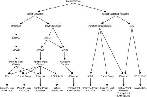 Packet-based Layer 2 VPNs are defined as Layer 2 VPNs that are delivered using a packet infrastructure, whereas circuit-based Layer 2 VPNs are Layer 2 VPNs that are delivered using the traditional Layer 2 infrastructure, such as ATM or Frame Relay switches or traditional Ethernet switches. The circuit or switched network-based Layer 2 VPNs are the most common means of delivering Layer 2 VPNs today and are well known in the industry. Today, most providers, including incumbent local exchange carriers (ILEC), deliver Layer 2 VPN services using ATM/FR switched infrastructure. In this chapter, we do not address the topic of how to build Layer 2 VPNs using traditional Layer 2 switches. Instead, we focus on how to build Layer 2 VPNs using packet infrastructure with MPLS. We provide only a cost differential comparison in building complete networks for delivering various services. In that context, we compare Layer 2 VPNs built using Frame Relay (FR) or ATM switches with that of packet infrastructure. Moving to the second layer of the taxonomy, packet-based Layer 2 VPNs can be delivered using IP/MPLS or native IP-based infrastructure using pseudowires. The Internet Engineering Task Force (IETF) defines a pseudowire as follows: "A pseudo-wire (PW) is a connection between two provider edge (PE) devices which connects two pseudo-wire end-services (PWES) of the same type." Layer 2 frames are encapsulated in IP/MPLS packets and transported across the packet network. At the remote end, the encapsulation is removed, the packet is converted to native Layer 2 format, and the packet is transported to the customer site. The IETF defines a reference model, known as the "PWE3 reference model" within the PWE3 (Pseudowire Emulation Edge-to-Edge) working group in RFC 3985. Refer to http://www.ietf.org/html.charters/pwe3-charter.html for more details. The PWE reference model is applicable to both IP- and MPLS-based networks. To better understand the terminology, refer to Figure 4-3. Figure 4-3. Pseudowire Reference Model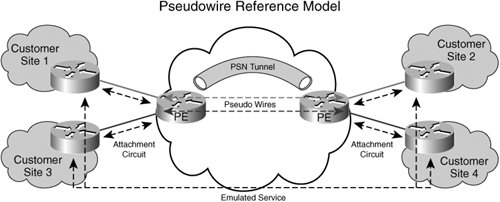 IETF has organized the area of packet-based L2 VPNs into two areas: the PWE Working Group and L2 VPN Working Group. The PWE3 Working Group deals with the signaling, transport, and encapsulation of a single point-to-point connection/pseudowire across the packet-based network, whereas the L2VPN Working Group discusses the auto-discovery and provisioning of L2 end points. The connection between the customer edge (CE) and the provider edge (PE) is a native Layer 2 circuit called the attachment circuit (AC). An AC can be any of the following:
In short, it attaches a CE device to a PE device. Figure 4-2 diagrams all the types of attachment circuits. The virtual connection between the PEs that connects the two attachment circuits on either side of the network is called a pseudowire, as shown in Figure 4-3. The pseudowire (PW) carries Layer 2 frames, with or without Layer 2 headers, across the packet infrastructure. The pseudowire is set up using signaling mechanisms, such as directed LDP in the case of an IP/MPLS network or L2TPv3 signaling for a native IP network. You can use other signaling protocols for signaling a pseudowire, but that usage is not covered in this chapter. Only the two most popular methods of building pseudowires are discussed in this chapter. When Layer 2 frames arrive at the PE router, they can be appropriately encapsulated and forwarded onto the pseudowire. The pseudowire is mapped to a packet switched network (PSN) tunnel setup using some encapsulation mechanism. The PSN tunnel is a mechanism of forwarding frames from PE1 to PE2. In the case of MPLS, the PSN tunnel could be a traffic-engineered tunnel or a PE1-PE2 labeled switched path (LSP). Now let us examine the MPLS-based Layer 2 VPNs in more detail. As mentioned earlier, the basic building block of MPLS-based Layer 2 VPNs is AToM. |
EAN: 2147483647
Pages: 162