Equipment Scalability Versus Network Scalability
| Scalability is an important factor when considering technology and equipment for deployment. Technology with limited scalability has severely limited applications. Specially, when MPLS is deployed by large service providers, you must understand how well MPLS scales and the role equipment scalability plays in scaling the overall network deployment. We have stated in earlier chapters that equipment scalability must not hamper network scalability. However, when equipment runs into its bounds, adding more network elements can help scale the network; however, it also means more devices to manage. After a point, even adding more equipment can no longer provide the same linear change that is expectedthis is called the point of inflexion. The farther the point of inflexion on the scalability chart, the better the overall scale factor. Let us quantitatively define some things. We have also shown in Chapters 4, "Layer 2 VPNs," and 5, "Layer 3 VPNs," that a network with MPLS network scalability is not an issue because devices can be added, and no single device is a bottleneck in building L3VPNs or L2VPNs. Assume we are determining the scale factor of an L3 network. To establish the scale factor, we need to understand the network element scalability. The parameters influencing the scale of the network elements are as follows:
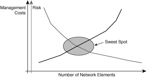
Network element characteristics determine the maximum number of network parameters possible on a device in isolation. However, even if a device is capable of supporting large numbers of each of these parameters in isolation, the device will not necessarily scale well in a real network. This is simply because none of these network parameters will be deployed/configured in isolation within the network. In a real network, the combination of these parameters matters. Hence, as an example, a device must not just be able to support a million prefixes, but must also support a large IGP table; label allocation for all those routes using LDP, BGP, or RSVP; thousands of L2 VCs; and hundreds or even thousands of IP interfaces all at the same time while passing traffic on each of the data paths. You might think such a network device is nonexistent. In an ideal world, a network element can be configured with all the previously mentioned parameters with huge scale numbers for each and be able to pass traffic at line rate on all ports. However, practically speaking, irrespective of the vendor, it is rarely the case. Hence, the operational paradigm is important to determine what the reasonable scale numbers for a network element are. Decision-makers evaluating equipment for NGN must find their operational sweet spot. Having a highly scalable network element can drive the CAPEX up by running up the cost per unit, and whether it really drives the OPEX down is unclear because fewer devices are required in the network for the same customer base. This is because the OPEX is mainly associated with customer end-point management rather than network core or network edge (PE) management. Moreover, configuring all services with large numbers of VPNs and L2 circuits equates to placing all your eggs in a single basket. The decision-makers must also determine whether the risk of placing all the services on a single node warrants the benefit gained by the cost reduction that can be attributed to using fewer devices for the same subscriber base. Should the highly scalable device fail or need to be taken out of service for any reason, the failure can affect many users. Figure 13-5 shows the plot of network elements versus management cost. The fewer the network elements, the lower the management cost. Figure 13-5. Management Costs and Risks However, the fewer the network elements, the higher the risk of outage for subscribers. Network Element CharacteristicsAdditionally, IP NGN managers and decision-makers must also determine how these network elements interact in the network. What happens when the IGP is too large or when a VPN is too large? They must design routing such that the network is appropriately segmented in areas or ASes such that any change in network does not impact the entire network but only that portion of the network where the change has occurred. Let us now briefly discuss each of those parameters that determine network element scalability:
Network ParametersThis section discusses network parameters and their scale requirements that must be met by network elements in designing a robust IP NGN.
Combinations of one or more factors can compound the effect on the router, and scale is affected. For example, in isolation a router might be able to handle 5000 QoS policies. However, when combined with BGP sessions, traffic engineering tunnels the number of QoS policies supported might be lower than in an isolated case. When sizing equipment, you must take these things into consideration. Perhaps the best and surest method for SPs, especially when scale is an issue, is to create a lab environment and test it with the configuration with which the router is going to be deployed. Network-Wide ScaleHaving discussed the various parameters required for the scale of network elements, let us also briefly discuss the network-wide scale issues:
Management and ScalabilityNetwork elements must support, at a minimum, manageability with MIBs and applications. The degree of support acceptable is dependent on the provider. ILECs and PTTs require full SNMP support and full MIB support with counter information on packets, bytes, and LSPs including per VPN and per class of service. However, network elements must scale well when the network management (NM) stations poll these devices for statistics. The ability to process NM requests accurately and the ability to inform NM stations during failure conditions via SNMP notifications are critical to the operation of the network element. Other scale issues in managing large networks exist when thousands of sites and thousands of VPNs are deployed. These factors are network and operation dependent. Having a provisioning system that can provision thousands of CEs and PEs to connect the VPN sites together is important. Operators cannot rely on the CLI and show commands anymore. Automated management and monitoring tools become necessarynot just necessary, but mandatoryas networks grow larger.
When building IP NGN, decision-makers must evaluate which factors are most important to their operational environment and which factors provide the margin to grow their network up to the next upgrade period. As we all know, in reality no network elements can last through network growth forever, and therefore, a determination must be made on how to strike the right balance. A simple rule is to pick the sweet spot based on operational experience and to maximize the return on investment based on that sweet spot. For example, if 10,000 VCs are provisioned in the current Frame Relay edge switch for subscribers, the multi-service device may also support a similar number of VCs (maybe not the same because the multi-service edge [MSE] network element might also support Layer 3 services at the same time). Layer 2 VPNsWhat to ExpectOften service providers worry whether they will be able to offer the same grade of service on a packet network with multi-service devices using MPLS that they offer today in the traditional Layer 2 switched networks. This is a valid concern. In addition, enterprise customers also would like to know how their service is being delivered and what to expect from the provider. In this section, we deal briefly with this topic and outline some points that decision-makers must consider to set the right expectations. Same Grade of ServiceToday SPs offer multiple grades of services on the Layer 2 network. These range from zero CIR for FR and unspecified bit rate (UBR) ATM service to well-defined bandwidth bounds using variable bit rate (VBR) or CBR services. The SPs also offer a leased connection with PPP or HDLC framing with a clocking/bandwidth rate on a Layer 1 network. Therefore, the question is whether this all can be emulated easily across a packet network. The answer, however, is not a simple one. Although some services such as UBR service or zero CIR service can easily be emulated, perfectly emulating a CBR service on a packet network is difficult, especially the cell delay variation tolerance (CDVT). However, providing a bandwidth bound equivalent to a VBR service is certainly possible. In small quantities, a CBR service is also possible, depending on the available bandwidth on the links in the network core during transient periods. For example, a provider might be able to get away with offering an ATM CBR service on an MPLS packet network by reserving a good deal of bandwidth to account for transient spikes in the network load or if the core links in the network are lightly loaded even during peak-hour traffic bursts. Offering bandwidth guarantees on a packet network requires QoS capabilities on the network elements. The ability to police traffic per VC and rate shape traffic becomes important to keep the bandwidth bounds of the service. QoS techniques combined with MPLS TE and maybe even DiffServ TE becomes necessary to build a Layer 2 service with similar QoS guarantees as a traditional Layer 2 network. More details on this can be found in Chapter 4, "Layer 2 VPNs" and Chapter 9, "Quality of Service." Enterprise customers expect to be able to do the same things as they do on a traditional Layer 2 network. As long as their traffic contracts are met, they do not care how the service is delivered across the network. Planning and SizingWith spatial and temporal gambling (also called statistical multiplexing), service providers overbook their capacity or use. With spatial gambling, service providers overbook and assume that not everyone uses the same space. Temporal gambling allows them to overbook the same space in different time slots, assuming not every one uses the network at the same time. This overbooking concept is well understood and is used in sizing the trunk capacity of the Layer 2 network. The same calculation might not apply to MPLS networks. MPLS networks use load balancing techniques, and they transport Layer 3 traffic. These planning and sizing tools need to be modified to account for the nature of packet networks. We do not mean to scare you by presenting all the issues up front, but our aim is to ensure that you understand the issues involved and find your way around them. DensityCurrent Layer 2 switches have a very high density of aggregation of Layer 2 VCs, be they Ethernet VLANs or ATM VCs. Current-generation hardware in the multi-service switches cannot match the same densities of traditional Layer 2 switches for Layer 2 services. The Layer 2 density is built to accommodate Layer 3 services. So, an MSE is not a direct replacement for a traditional switch; hence, the operation model must adjust to the new device densities. However, we have stated earlier that as providers are converging network architectures using MPLS, they are primarily using the cap and grow model, whereby they cap investment on the traditional Layer 2 networks and grow the multi-service network for all services. ManagementCurrent Layer 2 networks have evolved over a decade. The problems are well understood and there is considerable operational experience today with the current Layer 2 model. The management tools have also evolved to provide robust provisioning, configuration, and fault and diagnostics management. Many providers use these tools to provide fault monitoring and isolation as well as for billing, including usage-based billing. For IP networks, ubiquitous connectivity is more critical than usage-based connectivity. The two models are rather different when it comes to management, and the models have not come together. Network management vendors are making a concerted effort to allow provisioning of L2 and L3 VPNs and to provide a consistent feature set. It is only a matter of time before tools evolve to support both services in a consistent manner. Decision-makers must evaluate what is mandatory and what is highly desired when it comes to Layer 2 services. |
EAN: 2147483647
Pages: 162