5.5. Implementing, Managing, and Maintaining Routing and Remote Access Local area networks (LANs), wide area networks (WANs), dial-up connections, and virtual private networks (VPNs) all have increasing roles in the connected workplace, which means routing and remote access are an increasingly significant area of responsibility for today's administrators. Administrators are expected to know which of the myriad of routing and remote access options available to use when a need arises, and they are expected to know how to manage and maintain the implemented technologies. 5.5.1. Understanding Routing and Remote Access Using the Routing And Remote Access Service (RRAS), Windows Server 2003 can be configured as a multipurpose remote access server and IP router for connecting LANs to LANs, LANs to WANs, dial-up to LANs, and VPNs to LANs. The key advantages of using Windows Server 2003 in this role are that it allows easier management, support, and network integration as compared to hardware routers. Ease of management, support, and integration come primarily from the fact that administrators implement access controls and permission rules using standard Windows security and group policies. In the role as remote access server, a RRAS server can be configured for: Remote access over wireless, dial-up, or VPN, which enables computers to connect to the server using a dial-up or VPN connection. Network Address Translation (NAT), which allows internal computers to access the Internet using a public IP address from an assigned address pool. VPN and NAT, which allows remote clients to connect to the server through the Internet, and local clients to connect to the Internet using a public IP address from an assigned address pool. Secure connections between two private networks, which can be used to connect the network on which the server is located to a remote network. Custom configuration, which allows any combination of the available features.
Following this, a single RRAS server can handle both remote access and NAT. Remote access can also be configured for switched Ethernet connections and secure connections between private networks. In the role as IP router, a RRAS server can be configured with static routing tables and one or more network routing protocols. Each routing protocol has a different intended purpose and function. The routing protocols you'll typically work with include:
DHCP Relay Agent routing protocol Allows the server to route DHCP broadcast messages between subnets. DHCP Relay Agent routing protocol is essential for organizations with centralized DHCP servers and multiple subnets.
Routing Information Protocol (RIP) Version 2 for Internet Protocol Allows dynamic routing between subnets. RIP is an easily managed routing protocol, but limited to a maximum hop count of 15. For successful communications, source and destination computers can have no more than 15 routing devices between them.
Open Shortest Path First (OSPF) Allows extended dynamic routing between subnets. With OSPF, source and destination computers can have more than 15 routing devices between them. However, OSPF is more complex to configure and maintain than RIP. The Routing And Remote Access console is used to manage all aspects of RRAS. To access the console, click Start  Programs Administrative Tools Routing And Remote Access. When you start the console on a RRAS server, the console connects automatically to RRAS on this server. If you start the RRAS console on your workstation or want to connect to a different RRAS server, you can do this by right-clicking the Routing And Remote Access node and selecting Add Server. You can then use the Add Server dialog box to select the remote server you want to work with by its fully qualified domain name or IP address. Programs Administrative Tools Routing And Remote Access. When you start the console on a RRAS server, the console connects automatically to RRAS on this server. If you start the RRAS console on your workstation or want to connect to a different RRAS server, you can do this by right-clicking the Routing And Remote Access node and selecting Add Server. You can then use the Add Server dialog box to select the remote server you want to work with by its fully qualified domain name or IP address. The status of all servers to which you are connected can be viewed by clicking the Server Status node. As shown in Figure 5-37, servers are listed by name, type, state, ports in use, total ports, and uptime in days:hours:minutes. To manage the underlying service, right-click a server entry, click All Tasks, and then select Start, Stop, Pause, or Restart as appropriate. Figure 5-37. View the status of RRAS servers using the Server Status node. 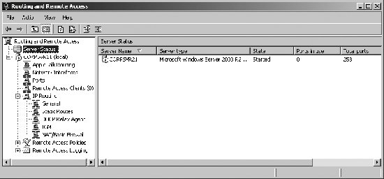
By default, the Routing And Remote Access service is installed by Windows Server 2003 Setup but is disabled. Before you can use RRAS, you must enable and preliminarily configure RRAS. Once you've done this, you must complete the configuration of each remote access and IP routing feature you plan to use. Thus, the process for completing the setup of RRAS requires the following: Implementing Routing and Remote Access Service. Adding and configuring necessary network interfaces. Configuring Routing and Remote Access Service properties. Adding and configuring necessary IP routing protocols.
5.5.2. Implementing Routing and Remote Access Before you can configure a RRAS server in any role, you must configure the server for Routing And Remote Access and then enable the Routing And Remote Access Service. Routing And Remote Access servers cannot use the Windows Firewall/Internet Connection Sharing service. To disable the Windows Firewall/Internet Connection Sharing service, follow these steps: Click Start  Programs Administrative Tools Services. Programs Administrative Tools Services. Right-click Windows Firewall/Internet Connection Sharing and select Properties. Set Startup Type to Disabled and then click OK.
The Routing And Remote Access service is installed by Windows Server 2003 Setup but is disabled. You can enable and preliminarily configure this service by completing these steps: Open Routing And Remote Access. Connect to the server you want to work with (if necessary). Right-click the server entry and then select Configure And Enable Routing And Remote Access. When the Routing And Remote Access Server Setup wizard starts, click Next. Select Custom Configuration and then click Next. As shown in Figure 5-38, you can now select the services that you want to enable on the server. Select only the services you plan to configure. Figure 5-38. Configure a RRAS server to support the services you plan to implement.  Click Next, and then click Finish. When prompted to start the Routing And Remote Access service, click Yes.
During the installation, the RRAS server is made a member of the RAS And IAS Servers security group in the local domain. This membership is required for proper working of routing and remote access. 5.5.3. Adding Interfaces and Implementing Secure Access Between Private Networks Hardware routers have built-in ports that are used to connect network segments. By routing traffic from one port to another, a hardware router is able to route traffic between network segments. Generally, the number of network segments that can be connected depends on the number of built-in ports. With RRAS, the number of network segments that can be routed is dependent on the number of network interfaces installed on the RRAS server. For example, if a RRAS server has three network cards and two modem cards, RRAS can route traffic among five networks. The three types of network interfaces you can add and configure are: Network connections Dial-up connections VPN connections
These three connections are added and configured in different ways. Only VPN connections are used to implement secure access between private networks. 5.5.3.1. Adding and configuring interfaces for network connections When you run the Routing And Remote Access Server Setup wizard, it attempts to automatically detect all installed network interfaces. The detected network interfaces are then listed on the Network Interfaces node in the Routing And Remote Access console. When you access the Network Interfaces node, you should see a local area connection for each interface card. You'll also see an interface listing for the local loopback interface and a local internal interface. If you install a new network after you configure RRAS, you'll need to manually add the interface. To manually add a routing interface, follow these steps: Open Routing And Remote Access. Connect to the server you want to work with (if necessary). Expand the server node and the related IP-routing node. Right-click the General node and then select New Interface. In the Interfaces dialog box, click the new interface to add, and then click OK. If prompted, configure the interface as appropriate.
5.5.3.2. Adding and configuring interfaces for dial-up connections Preconfigured dial-up connections are not automatically added or configured. If you want to configure routing through on-demand or persistent dial-up connections, you must add these connections manually as demand-dial interfaces. To add as demand-dial interfaces, follow these steps: Open Routing And Remote Access. Connect to the server you want to work with (if necessary). Expand the server node. Right-click the Network Interfaces node and then select New Demand-Dial Interface. When the Demand-Dial Interface Wizard starts, click Next. Enter a name for the interface. Click Next. Select Connect Using A Modem, ISDN, Or Other Physical Device. Click Next. Continue with the rest of the wizards screen.
5.5.3.3. Adding and configuring interfaces for VPN and PPPoE connections VPN and Point-to-Point Protocol over Ethernet (PPPoE) are used for secure communications between private networks. Although the private networks can be either directly connected or connected over dial-up, VPN and PPPoE connections are configured manually as demand-dial interfaces. To add a demand dial interface for VPN or PPPoE, follow these steps: Open Routing And Remote Access. Connect to the server you want to work with (if necessary). Expand the server node. Right-click the Network Interfaces node and then select New Demand-Dial Interface. When the Demand-Dial Interface Wizard starts, click Next. Enter a name for the interface. Click Next. Select either the Connect Using Virtual Private Networking (VPN) radio button or the Connect Using PPP Over Ethernet (PPoE) radio button as appropriate. Click Next. If you are configuring VPN, choose the type of VPN interface and then click Next. Both Point-to-Point Tunneling Protocol (PPTP) and Layer 2 Tunneling Protocol (L2TP) are supported. By default, the appropriate protocol can be automatically selected when a connection is made. However, only L2TP uses IPSec for advanced encryption, making it more secure. Click Next. If you are configuring PPPoE, optionally type the name of your organization's broadband connection provider. Click Next. Enter the IP address of the router to which you are connecting, as shown in Figure 5-39. Click Next. Figure 5-39. Specify the destination address for the VPN connection. 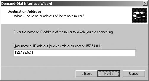 Select the transports and security options. The Route IP Packets On This Interface checkbox is selected by default. Click Next. Specify the permanent static routes to the remote networks with which this network will communicate (see Figure 5-40). Click Add. In the Destination field, enter the network ID of the destination network. In the Network Mask field, enter the network mask of the destination network. In the Metric field, enter the relative cost of routing via this router. Click OK. Figure 5-40. Specify static routes by the network ID, network mask, and metric. 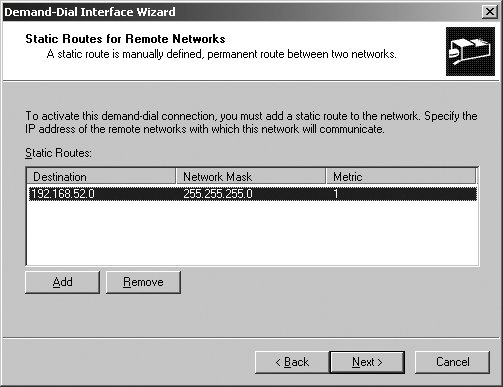 Repeat Step 9 to add other static routes. Click Next when you are ready to continue. Click Next. Enter the user credentials to use to connect to the remote router. Click Next, and then click Finish.
5.5.4. Configuring Remote Access Server Service Properties RRAS server properties are used to configure many aspects of remote access, including user authentication. In the Routing And Remote Access console, access server properties by right-clicking the server node and selecting Properties. Although most changes are applied automatically, some changes, such as modification of authentication providers, require that you restart the Routing And Remote Access service. To do this, right-click a server entry, click All Tasks, and then select Restart. If you want to completely disable RRAS, right-click the server entry and then select Disable Routing And Remote Access. 5.5.4.1. Managing the Remote Access Server configuration If you right-click a server entry in the Routing And Remote Access console and select Properties, you can use the General tab options to reconfigure RRAS (see Figure 5-41). The following list describes the options available: Figure 5-41. Modify the RRAS configuration as necessary using the General tab options. 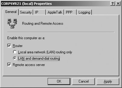
Router Enables IP routing for use with DHCP relay agents, RIP, OSPF, etc.
Local Area Network (LAN) Routing Only Limits IP routing to LAN routing only, and does not allow demand-dial or VPN connections between networks.
LAN and demand-dial routing Allows both LAN and demand-dial routing, and supports VPN connections between networks.
Remote Access Server Allows the server to handle remote access connections from clients that use either dial-up or VPN. 5.5.4.2. Managing remote access security If you right-click a server entry in the Routing And Remote Access console and select Properties, you can use the Security tab options to configure remote access security (see Figure 5-42). The Authentication Provider list lets you specify how remote access clients and demand-dial routers are authenticated. The authentication options are: Figure 5-42. Configure RRAS server security. 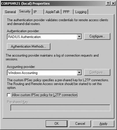
Windows Authentication The default authentication method is Windows Authentication, which lets you use standard Windows security for authentication.
RADIUS Authentication Remote Authentication Dial-in User Service (RADIUS) should be used only if your organization has RADIUS servers, which are used to centralize the authentication of remote access clients and the storage of accounting information. The Accounting Provider list lets you specify whether and how connection requests and sessions are logged. The accounting options are:
None Turns off logging of connection requests and sessions.
Windows Accounting Logs connection request and sessions in logfiles stored in the Remote Access Logging folder.
RADIUS Accounting Sends details about connection request and sessions to the RADIUS server. The RADIUS server in turn logs this information. The final security option you can set for an RRAS server is used with VPN. If you've configured VPN and set L2TP as the protocol type, you can use IPSec with L2TP to enhance security. To do this, you must define a custom IPSec policy and enable the related security options for your RRAS server by doing the following: Right-click a server entry in the Routing And Remote Access console and select Properties. Click the Security tab. Select the Allow Custom IPSec Policy For L2TP Connection checkbox. In the Pre-Shared Key text box, type a preshared key to use with the custom IPSec policy. Each client computer that will remotely access the network over VPN and be subject to the IPSec policy must be configured with the same preshared key.
5.5.4.3. Managing user authentication Security is a critical component of routing and remote access. In a standard configuration of RRAS, the RRAS server uses Windows authentication to authenticate remote clients and logs connection request and session details in the System event logs. The way the user credentials are sent to the RRAS server depends on the permitted authentication methods, which can be set by following these steps: Right-click a server entry in the Routing And Remote Access console, and then select Properties. Click the Security tab. Click the Authentication Methods button. As Figure 5-43 shows, there are many available methods for sending authentication credentials to a RRAS server. Figure 5-43. Configure the permitted user authentication methods. 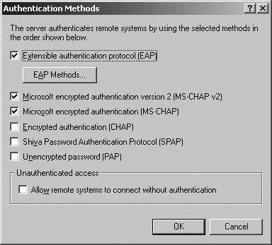
When remote clients attempt to connect to the RRAS server, the server attempts to authenticate the client using the selected authentication methods. The authentication methods are used in the order shown and are essentially organized from the most secure to the least secure. The available user authentication methods are:
Extensible Authentication Protocol (EAP) Extensible Authentication Protocol (EAP) extends the authentication methods for PPP connections to include the EAP methods configured through remote access policies. In a standard configuration, these policies allow MD5-Challenge, Protected EAP (PEAP), Smart card, or other PKI certificate to be used.
Tip: EAP is required if you want to use smart cards with remote access clients.
Microsoft Encrypted Authentication version 2 (MS-CHAP v2) Microsoft Encrypted Authentication version 2 (MS-CHAP v2) uses Microsoft Challenge Handshake Authentication Protocol (MS-CHAP) version 2 to authenticate remote access and demand-dial connections using mutual authentication and strong encryption. MS-CHAP v2 is required for encrypted PPP and PPTP connections.
Microsoft Encrypted Authentication (MS-CHAP) Microsoft Encrypted Authentication (MS-CHAP) uses Microsoft Challenge Handshake Authentication Protocol (MS-CHAP) to authenticate remote access and demand-dial connections using encryption. MS-CHAP is required for encrypted PPP and PPTP connections.
Encrypted Authentication (CHAP) Encrypted Authentication (CHAP) uses MD-5 Challenge Handshake Authentication Protocol (CHAP) to authenticate remote access and demand-dial connections using encryption.
Shiva Password Authentication Protocol (SPAP) Shiva Password Authentication Protocol (SPAP) uses authentication with reversible encryption and is compatible with Shiva LAN Rover and Shiva clients. SPAP is not secure.
Unencrypted Password (PAP) Unencrypted Password (PAP) uses Password Authentication Protocol (PAP) and sends passwords in plain-text during authentication. PAP is the most unsecure authentication method. Remote access policies for use with EAP are specified using the Remote Access Policies node in the Routing And Remote Access console. Policies are applied in priority order. The two standard policies are: Connections To Microsoft Routing And Remote Access Server, which applies to connections to the currently selected RRAS server. Connections To Other Access Servers, which applies to connections to other access servers via the current server.
These policies are extremely important when your organization uses RADIUS servers for centralizing remote access client authentication. New remote access policies can be created by right-clicking the Remote Access Policies node in the Routing And Remote Access console, selecting New Remote Access Policy, and then following the prompts by the New Remote Access Policy Wizard. Each policy can have a dial-in profile associated with it, which is used to set access permissions. Right-click a policy, select Properties, and then click the Edit Profile button to view and modify the profile settings. Remote access settings defined in a user's profile have precedence over dial-in profile settings. 5.5.4.4. Managing IP assignment If you right-click a server entry in the Routing And Remote Access console and select Properties, you can use the IP tab options to configure IP assignment (see Figure 5-44). IP assignment settings determine whether and how remote access clients are assigned IP addresses. Figure 5-44. Configure IP address assignment. 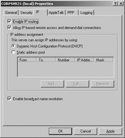
The IP assignment options you can configure are:
Enable IP Routing IP Routing controls the forwarding of IP packets from one routing interface to another. You must select the IP Routing checkbox for LAN and demand-dial routing to occur. If you want IP-based remote access clients to be able to access the entire network to which the RRAS server is attached, select the IP Routing checkbox. If you want IP-based remote access clients to be able to access the RRAS server but not the network, clear the Enable IP Routing checkbox.
Allow IP-based Remote Access And Demand-Dial Connections If you select the Allow IP-based Remote Access And Demand-Dial Connections checkbox, IP-based remote access and demand-dial connections can be established using RRAS. All Point-to-Point Protocol (PPP) connections will then negotiate connections using Internet Protocol Control Protocol (IPCP). The PPP settings used are configured on the PPP tab of the Properties dialog box.
Dynamic Host Configuration Protocol (DHCP) If you select this option, the RRAS server assigns client IP addresses using DHCP. On your organization's DHCP servers, you can use the Default Routing And Remote Access Class to define a separate configuration for remote access clients. If you do not do this, remote access clients will use the same configuration as other DHCP clients.
Tip: On your organization's DHCP server, the scopes must be large enough so that the RRAS servers can requests blocks of 10 IP addresses. There must be at least 10 free IP addresses available on the DHCP server for the RRAS clients.
Static Address Pool If you select this option, the RRAS server assigns remote access clients static IP addresses from the defined IP address pools. Click the Add button to define a range of IP addresses to use as an address pool.
Enable Broadcast Name Resolution If you select this option, remote access clients can use broadcast messages to resolve hostnames on the local subnet to which they connect without having to use WINS or DNS. Broadcasts are not forwarded to other subnets. 5.5.4.5. Managing remote access logging If you right-click a server entry in the Routing And Remote Access console and select Properties, you can use the Logging tab options to configure event logging and debugging. RRAS events are stored in the System event logs, and by default, only errors and warnings are recorded. You can modify the logging configuration to log errors only, to log all events, or to stop logging. For debugging connections to RRAS, you can select the Log Additional Routing And Remote Access Information checkbox. When debugging is enabled, PPP connection events for remote access and demand-dial routing connections are written to Ppp.log in the %SystemRoot%\Tracing folder. 5.5.5. Managing DHCP Relay Agents DHCP clients use broadcast messages to contact DHCP servers. Generally, broadcasts aren't routed between subnets and are limited by the logical boundaries of a subnet. Because of this, you normally need at least one DHCP server for each subnet in your organization. In large networks, it quickly can become impractical to have one DHCP server per subnet. You can work around this restriction by configuring DHCP relay agents on subnets. A relay agent is a router or a computer on the network that is configured to listen for DHCP broadcasts and forward the DHCP broadcasts between clients and servers. Any router that supports BOOTP forwarding i.e., routers that are RFC-1542 compliantcan be configured as a relay agent. With BOOTP forwarding, the router forwards DHCP broadcasts from DHCP clients to DHCP servers and informs the DHCP server of the originating subnet. This allows the responding DHCP server to assign addresses to remote clients from the appropriate scope. Using Routing And Remote Access, any Windows 2000 or later server can act as a DHCP relay agent as well. The process is similar to BOOTP forwarding, and the server acting as the relay agent doesn't need to be configured as a network router between subnets. To configure a server as a DHCP relay agent, you must perform the steps that follow: Install the DHCP Relay Agent routing protocol. Configure the DHCP Relay Agent routing protocol. Enable the DHCP Relay Agent routing protocol.
Once the DHCP Relay Agent routing protocol is installed, configured, and enabled, you can view the status by selecting the DHCP Relay Agent node in the Routing And Remote Access console. 5.5.5.1. Installing the DHCP Relay Agent routing protocol You can install the DHCP Relay Agent routing protocol by completing these steps: Open Routing And Remote Access. Connect to the server you want to work with (if necessary). Expand the server node, and then expand the IP Routing node. Right-click the General node, and then select New Routing Protocol. Click DHCP Relay Agent, and then click OK.
5.5.5.2. Configuring the DHCP Relay Agent routing protocol You can configure the DHCP Relay Agent routing protocol by completing these steps: Open Routing And Remote Access. Connect to the server you want to work with (if necessary). Expand the server node, and then expand the IP Routing node. Right-click DHCP Relay Agent, and then select Properties. Type the IP address of a DHCP server for the network, and then click Add. Repeat to specify additional DHCP servers. Click OK.
5.5.5.3. Enabling the DHCP Relay Agent routing protocol Once you've installed and configured the DHCP Relay Agent routing protocol, you must enable one or more of the server's network interfaces. To do this, follow these steps: Open Routing And Remote Access. Connect to the server you want to work with (if necessary). Expand the server node, and then expand the IP Routing node. Right-click DHCP Relay Agent, and then select New Interface. Click the network interface on which you want to enable the routing protocol. Click OK. A new dialog box is displayed with the Relay DHCP Packets checkbox selected by default. Use Hop-Count Threshold to set the maximum number of routers through which DHCP broadcasts can be relayed. The default is four. Use Boot Threshold (Seconds) to specify the number of seconds the relay agents waits before forwarding DHCP messages. The default is four seconds. Click OK.
5.5.6. Managing TCP/IP Routing When you install Routing And Remote Access and enable IP routing, you can add routing protocols. As discussed previously, the key protocols you'll work with are Routing Information Protocol (RIP) version 2 for Internet Protocol and Open Shortest Path First (OSPF). Also, as mentioned, both protocols allow you to dynamically manage routing. RIP is ideal for small networks because it is easy to set up and configure. OSPF is better for larger networks as it is more configurable and can be used on extended networks with more than 15 routers between segments. 5.5.6.1. Installing RIP and OSPF You can install the RIP or OSPF routing protocol by completing these steps: Open Routing And Remote Access. Connect to the server you want to work with (if necessary). Expand the server node, and then expand the IP Routing node. Right-click the General node, and then select New Routing Protocol. Click Routing Information Protocol (RIP) version 2 for Internet Protocol or Open Shortest Path First (OSPF) as appropriate. Click OK.
After RIP and OSPF have been installed, you can configure them as follows in "Configuring RIP" and "Configuring OSPF," respectively. 5.5.6.2. Configuring RIP When an RIP router is initially configured, the only entries in its routing tables are for the networks to which it is physically connected. The router then starts sending announcements of its availability to other routers of the networks it services. Responses from announcements allow the router to update its routing tables. The way announcements are made depends on the operating mode. One of two operation modes can be selected: periodic update mode, in which RIP announcements are sent periodically to learn of available routes, and routes are deleted automatically when the router is stopped and restarted; and auto-static update mode, in which RIP announcements are sent when other routers request updates, learned routes are added as static, and routes remain until they are manually deleted. When changes occur to the network topology, RIP version 2 uses triggered updates to communicate the changes to other routers. After RIP has been installed, you must specify the network interface or interfaces through which the protocol will be used. To do this, follow these steps: Open Routing And Remote Access. Connect to the server you want to work with (if necessary). Expand the server node, and then expand the IP Routing node. Right-click the RIP node, and then select New Interface. Select one of the available network interfaces through which RIP traffic can be routed. Any available interface can be selected, and the same interface can be used by multiple IP routing protocols. Click OK.
The RIP Properties dialog box is displayed. You can now configure RIP as discussed in this section. The RIP Properties dialog box can also be displayed by right-clicking the RIP node and then selecting Properties. The RIP Properties dialog box has two tabs:
General The General tab options control triggered update delays and event logging. By default, the maximum amount of time the router waits before it sends triggered updates is five seconds. By default, only errors are logged. You can modify these settings as necessary.
Security The Security tab options control how the router processes announcements. By default announcements from all routers are accepted. You can modify this so only announcements from listed routers are accepted, or so announcements from all routers except those listed are accepted. After you set the general RIP options, set the connection properties. The connection Properties dialog box can also be displayed by clicking the RIP node in the left pane, right-clicking the network interface, and then selecting Properties. As shown in Figure 5-45, the connection Properties dialog box has four tabs: Figure 5-45. Configuring routing properties for RIP. 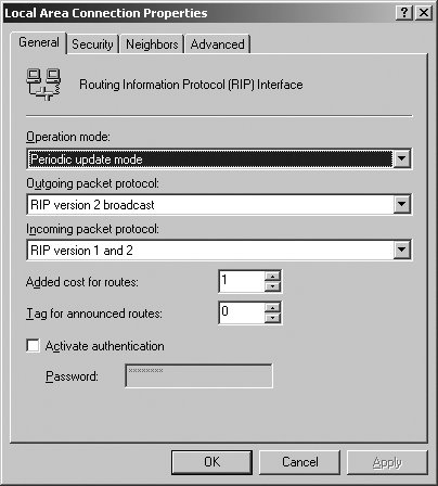
General The General tab options allow you to configure the operation mode, packet protocol, and authentication. One of two operation modes can be selected: periodic update mode or auto-static update mode. The outgoing and incoming packet protocol options let you specify the required protocol compliance levels. The Activate Authentication and Password options let you enable authentication for all incoming and outgoing packets. When authentication is used, neighboring routers must be configured with identical authentication passwords. These passwords are sent in clear text.
Security The Security tab options allow you to configure RIP route filters. For incoming routes, the router can be configured to accept all routes, accept all routes in the ranges listed, or allow all routes except those specifically ignored. For outgoing routes, the router can be configured to announce all routes, announce all routes in the ranges listed, or to announce all routes except for those specifically ignored.
Neighbors The Neighbors tab options allow you to configure how the router interacts with other RIP routers. By default, the router uses broadcasts or multicast only, and doesn't have defined neighbors. You can add specific neighbor routers in addition to or instead of broadcast or multicast.
Advanced The Advanced tab options control periodic announcements, routing expiration and processing. 5.5.6.3. Configuring OSPF OSPF uses the Shortest Path First (SPF) algorithm to calculate routes. The route with the lowest route cost is the shortest path, and the shortest path is always used first when routing. An OSPF router maintains a link-state database that it uses to track the network topology. The database is synchronized with adjacent routers or specifically defined nonbroadcast multiple access (NBMA) neighbors. When a change is made to the network topology, the first router to identify the change sends out a change notification. This change notification is used to update the link-state database so that the routing tables can be recalculated automatically. Unlike RIP, OSPF divides the network into transit areas, which can be thought of as areas of responsibility. OSPF routers maintain link-state information only for those transit areas for which they've been configured. After OSPF has been installed, you must specify the network interface or interfaces through which the protocol will be used. To do this, follow these steps: Open Routing And Remote Access. Connect to the server you want to work with (if necessary). Expand the server node, and then expand the IP Routing node. Right-click the OSPF node, and then select New Interface. Select one of the available network interfaces through which RIP traffic can be routed. Any available interface can be selected, and the same interface can be used by multiple IP routing protocols. Click OK.
The OSPF Properties dialog box is displayed. You can now configure OSPF as discussed in this section. The OSPF Properties dialog box can also be displayed by right-clicking the OSPF node and then selecting Properties. The OSPF Properties dialog box has four tabs:
General The General tab options set the router ID and control event logging. The network ID is set to the IP address of the connection automatically. By default, only errors are logged. You can modify these settings as necessary. Autonomous System Boundary Router can also be enabled to advertise external routing information from other route sources, such as static routes or OSPF.
Areas The Areas tab options can be used to subdivide the network into specific transit areas. The default area is 0.0.0.0, which represents the backbone of the current network.
Virtual Interfaces The Virtual Interfaces tab options allow you to configure virtual interfaces for transit areas.
External Routing The External Routing tab options allow you to configure Autonomous System Boundary Routing. By default, when enabled, all routes from all route sources are accepted. After you set the general OSPF options, you should set the properties for connections, virtual connections, or both. The related Properties dialog box can also be displayed by clicking the OSPF node in the left pane, right-clicking the connection and then selecting Properties. The connection Properties dialog box includes these tabs:
General The General tab options allow you to configure the area ID, router priority, cost, and password. Using the Network Type options, you can specify whether the router is a broadcast interface, point-to-point interface, or nonbroadcast multiple access (NBMA) interface.
NMBA Neighbors When the network type is an NBMA interface, the NMBA Neighbors tab options allow you to specify the IP addresses and router priority of NMBA neighbors.
Advanced The Advanced tab options control transit delays, retransmit intervals, Hello intervals for discovery, Dead intervals for determining down routers, and poll intervals for follow-ups to dead routers. The default maximum transmission unit is 1,500 bytes. This is the standard packet size of IP networks. 5.5.6.4. Configuring routing tables Although RIP and OSPF allow dynamic routing, you sometimes need to use static routing. Static routes provide a permanent mapping to a specific destination network, according to the network ID, network mask, and relative cost of the route. Routers can use this information to determine the gateway to use to forward packets so that hosts on a destination network can be reached. Static routes are not shared between routers. You can configure static routes using the Routing And Remote Access console or the route add command. To view existing static routes in the Routing And Remote Access console, follow these steps: Open Routing And Remote Access. Connect to the server you want to work with (if necessary). Expand the server node, and then expand the IP Routing node. Click the Static Routes node. When no routes are configured, the default route with a destination address and subnet mask of 0.0.0.0 is shown.
To add a static route using the Routing And Remote Access console, follow these steps: Open Routing And Remote Access. Connect to the server you want to work with (if necessary). Expand the server node, and then expand the IP Routing node. Right-click the Static Routes node, and then select New Static Route. In the Static Route dialog box shown in Figure 5-46, specify the interface for which the static route will be used. Figure 5-46. Configure the static route.  In the Destination and Network Mask fields, specify the destination network ID and network mask. In the Gateway field, specify the IP address of the gateway for the RRAS server. In the Metric field, specify the relative cost of the route. Click OK.
In the Routing And Remote Access console, you can delete a static route by right-clicking it and then selecting Delete. Before you work with static routes at a command prompt, you should print the currently configured static routes by entering route print. The output of route print shows current interfaces, static routes, and persistent routes, as shown here: IPv4 Route Table =========================================================================== Interface List 0x1 ........................... MS TCP Loopback interface 0x10003 ...00 03 ff 6b ef 12 ...... Intel 21140-Based PCI Fast Ethernet Adapter (Generic) =========================================================================== =========================================================================== Active Routes: Network Destination Netmask Gateway Interface Metric 0.0.0.0 0.0.0.0 192.168.0.25 192.168.0.25 20 127.0.0.0 255.0.0.0 127.0.0.1 127.0.0.1 1 192.168.0.0 255.255.255.0 192.168.0.25 192.168.0.25 20 192.168.0.25 255.255.255.255 127.0.0.1 127.0.0.1 20 192.168.0.255 255.255.255.255 192.168.0.25 192.168.0.25 20 192.168.52.0 255.255.255.0 0.0.0.0 ffffffff 1 224.0.0.0 240.0.0.0 192.168.0.25 192.168.0.25 20 255.255.255.255 255.255.255.255 192.168.0.25 192.168.0.25 1 Default Gateway: 192.168.0.25 =========================================================================== Persistent Routes: None
If you've configured IPv6, you'll also see IPv6 routing details. Note the hex address of the interfaces in the Interface List. You refer to interfaces by this address. The syntax of the route add command follows: route add DestinationNetworkID mask NetworkMask Gateway metric MetricCost if Interface
You could configure the static route defined in Figure 5-46, using the following command: route add 192.168.52.0 mask 255.255.255.0 192.168.0.1 metric 1 if 0x10003
The metric and interface are optional. If you do not specify them, they are selected automatically. To make a static route persistent, you can use route add -p. Persistent static routes are not deleted even if the router is stopped and restarted. At the command prompt, you can delete a static route using route delete. The syntax is: route delete DestinationNetworkID
For example: route delete 192.168.52.0
5.5.6.5. Configuring routing ports When you install RRAS, a number of routing ports are created automatically. Routing ports are used for inbound connections to the RRAS server. The types of ports available depend on the configuration of the RRAS server. To view or reset ports, follow these steps: Open Routing And Remote Access. Connect to the server you want to work with (if necessary). Expand the server node. Click the Ports node. Configured ports are listed by type and status in the right pane. To view a port's status and statistics, double-click the port entry. To reset a port, double-click the port entry, and then click the Reset button.
You can configure ports by completing the following steps: Open Routing And Remote Access. Connect to the server you want to work with (if necessary). Expand the server node. Right-click the Ports node, and then select Properties. The Ports Properties dialog box shows the types of ports configured and the number of each type of port. To modify the configuration of all ports of a particular type, click the port name, and then click the Configure button. Using the Configure Device dialog box shown in Figure 5-47, specify how the port should be used and set the number of ports as necessary. Figure 5-47. Configure the device ports. 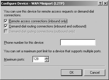 If you've configured PPPoE, there'll be a WAN miniport for PPPoE that is used for demand-dial routing of outbound-only connections. You can disable the use of the port by clearing the Demand-Dial Routing Connections checkbox in the Configure Device dialog box. If you've configured VPN using L2TP or PPTP, there'll be multiple WAN miniports for each protocol. The default configuration allows up to 128 ports. You can add ports by increasing the maximum ports option. You can configure the ports for remote access inbound use only, for inbound and outbound demand-dial routing connections, or for both.
Click OK.
5.5.7. Managing NAT and the Basic Firewall Network Address Translation (NAT) allows multiple client computers to access the public Internet sharing a single public IP address or a pool of public IP addresses. NAT separate your organization's internal private network from the public network so that you can use private IP addresses internally and use public IP addresses when client computers need to access the Internet. NAT provides Internet connectivity to internal clients through a single interface, which allows either a demand-dial or permanent connection. NAT includes the Basic Firewall that can be used to block external traffic from entering the internal network. In a typical secure configuration that includes a NAT server, the organization's network will use hardware firewalls as well, and the organization's network will be configured such that incoming traffic must first pass through the hardware firewall and then pass through the NAT server. This configuration is more secure and allows traffic to be blocked at the frontend hardware firewall before it reaches the NAT server. Using Routing And Remote Access, any Windows 2000 or later server can act as a NAT server and Basic Firewall. To configure a server for NAT and the Basic Firewall, you need to: Install the NAT/Basic Firewall routing protocol. Specify the Network Interface to use. Configure the NAT/Basic Firewall routing protocol. Optionally, enable basic firewall and configure packet filtering.
Once the NAT/Basic Firewall routing protocol is installed, configured, and enabled, you can view the status by selecting the NAT/Basic Firewall node in the Routing And Remote Access console. 5.5.7.1. Installing the NAT/Basic Firewall routing protocol You can install the NAT/Basic Firewall routing protocol by completing these steps: Open Routing And Remote Access. Connect to the server you want to work with (if necessary). Expand the server node, and then expand the IP Routing node. Right-click the General node, and then select New Routing Protocol. Click NAT/Basic Firewall, and then click OK.
5.5.7.2. Configuring the NAT/Basic Firewall routing protocol After NAT/Basic Firewall has been installed, you must specify the network interface or interfaces through which the protocol will be used. To do this, follow these steps: Open Routing And Remote Access. Connect to the server you want to work with (if necessary). Expand the server node, and then expand the IP Routing node. Right-click the NAT/Basic Firewall node, and then select New Interface. Select the interface that is directly connect to the Internet. Click OK.
You can now configure NAT and the Basic firewall as discussed in this section. The NAT/Basic Firewall Properties dialog box can also be displayed by right-clicking the NAT/Basic Firewall node, and then selecting Properties. As shown in Figure 5-48, the Network Address Translation Properties dialog box has four tabs: Figure 5-48. The NAT/Basic Firewall Properties dialog box. 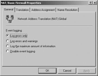
General The options on this tab are used to configure event logging. By default, errors only are logged.
Translation The options on this tab are used to specify when TCP and UDP mappings are removed. By default, TCP mappings are removed after 1,440 minutes, and UDP mappings are removed after 1 minute.
Address Assignment The options on this tab specify whether the NAT router provides DHCP-based IP addresses to DHCP clients on the private network. When internal clients are using NAT to access the public Internet, you typically do not need to enable address assignment.
Name Resolution The options on this tab specify whether the NAT router relays DNS name resolution requests from hosts on the private network to the configured DNS server for the router. When internal clients are using NAT to access the public Internet, you typically do not need to enable name resolution. 5.5.7.3. Enabling Basic Firewall and configuring packet filtering In the default configuration of NAT, Basic Firewall is not enabled for use with a public interface connected to the Internet. If you enable the Basic Firewall for use with a public interface connected to the Internet, the Basic Firewall accepts incoming traffic from the Internet only if it has been requested by the network. You can define packet filters to control network traffic using:
Inbound packet filters These control which packets are forwarded or processed by the network.
Outbound packet filters These control which packets are received by the network. To enable Basic Firewall and configure packet filtering for use with a public interface connected to the Internet, follow these steps: Open Routing And Remote Access. Connect to the server you want to work with (if necessary). Expand the server node, and then expand the IP Routing node. Click NAT/Basic Firewall and then double-click the network interface on which you want to configure. On the NAT/Basic Firewall tab, select the Enable A Basic Firewall On This Interface checkbox. Click the Inbound Filters button to specify which packets are forwarded or processed by the network. Click the Outbound Filters button to specify which packets are received by the network. Click OK.
5.5.8. Managing Remote Access Clients In the Routing And Remote Access console, you can view the currently connected clients by expanding the server node and then clicking the Remote Access Clients node. Clients are listed according to the connected username, duration, and number of access ports being used. You can manage remote access clients by:
Checking status of a client To view a more detailed status, right-click the client entry and then select Status.
Disconnecting a client To disconnect a client, right-click the client entry and then select Disconnect.
Sending a message to a client To send a message to a client, right-click the client entry, select Send Message, type the message, and then click OK.
Sending a message to all clients To send a message to all clients, right-click the Remote Access Clients node, select Send To All, type the message, and then click OK. Keep the following in mind as well: In Active Directory Users And Computers, you can set general remote access options on the Dial-in tab. These options are used for dial-in and VPN connections. In the Routing And Remote Access console, you can control remote access permissions using remote access policies.
5.5.9. Configuring IAS to Provide Authentication RADIUS servers are used to centralize the authentication of remote access clients and the storage of accounting information. Centralizing authentication and accounting reduces the administrative overhead of managing multiple RRAS servers. A Windows Server 2003 system can be configured as a RADIUS server by installing the Internet Authentication Service (IAS). To configure IAS for use in your organization, you need to: Install IAS on a designated server. Register the IAS server in Active Directory. Configure your RRAS servers as IAS clients. Configure your RRAS servers to use RADIUS.
5.5.9.1. Installing IAS A Windows Server 2003 system can be configured as a RADIUS server by installing the IAS. Install IAS by completing the following steps: Open Add Or Remove Programs in the Control Panel. In the Add Or Remove Programs window, click Add/Remove Windows Components. Click Networking Services and then select Properties. Be careful not to clear the checkbox. Select Internet Authentication Service and then click OK. Click Next. Setup configures the server's components. Click Finish.
You manage Internet Authentication Service using the Internet Authentication Service console shown in Figure 5-49, which can be accessed by clicking Start Programs Administrative Tools Internet Authentication Service. When you start the Internet Authentication Service console on an IAS server, the console connects automatically to IAS on this server. You cannot connect to other IAS servers. Figure 5-49. The Internet Authentication Service console. 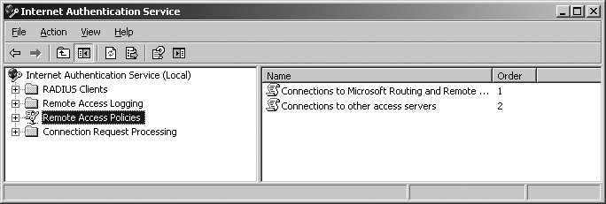
5.5.9.2. Registering the RADIUS server and configuring clients To complete the installation of the RADIUS server, you must register the server in Active Directory and tell RADIUS about the RRAS servers, which forwards authentication and accounting information to the RADIUS servers as clients. You can register the RADIUS server in Active Directory by completing the following steps: Open the Internet Authentication Service console. Right-click the Internet Authentication Service node. Select Register Server In Active Directory. If it is a domain controller, it is automatically registered in Active Directory.
Registering the server with Active Directory makes the server a member of the RAS And IAS Servers group. Members of this group are able to read remote access attributes of user accounts. To configure your RRAS servers as clients (as is required for forwarding of authentication and accounting information), follow these steps: Open the Internet Authentication Service console. Right-click the RADIUS Clients node and then select New Radius Client. Type the hostname of the RRAS server as the friendly name. Type the IP address of FQDN of the RRAS server. Click Next. Access RADIUS Standard as the Client-Server type. Type and then confirm the Shared Secret. This same shared secret must be set on your RRAS servers. Click Finish.
Once you've configured forwarding of authentication and accounting, the Routing And Remote Access service on an RRAS server forwards remote access requests to the designated IAS server. The IAS server, acting as a RADIUS server, manages authentication and accounting. You can also deploy the IAS service as a RADIUS proxy. In this configuration, the Routing And Remote Access service on an RRAS server forwards remote access requests to the IAS server, which is acting as a RADIUS proxy for a group of RADIUS servers. Members of the RADIUS servers group in turn manage authentication and accounting. Requests are load balanced dynamically by the IAS server acting as the RADIUS proxy. Connection request policies can be defined on the RADIUS proxy to sort access requests and send them to a specific RADIUS server. 5.5.9.3. Configure your RRAS servers to use RADIUS After you've installed IAS on your designated server or servers, you can tell other RRAS servers about the IAS servers, by completing the following steps: Right-click a server entry in the Routing And Remote Access console and select Properties. Click the Security tab. Specify that RADIUS should be used for authentication by selecting RADIUS Authentication as the Authentication Provider. Click Configure to specify the RADIUS server to use for authentication. Add the RADIUS servers in priority order. The UDP port over which connections can be made is by default UDP port 1812 (based on RFC 2138). Specify that RADIUS should be used for accounting by selecting RADIUS Accounting as the Accounting Provider. Click Configure to specify the RADIUS server to use for accounting. Add the RADIUS servers in priority order. The UDP port over which connections can be made is by default UDP port 1813 (based on RFC 2138). Click OK.
5.5.10. Troubleshooting User Access to Remote Access Services Troubleshooting is a critically important part of any administrator's job. Users connecting to remote access services can encounter many different types of problems when connecting to the network or accessing resources. If the RRAS server is configured as a router, proper routing depends on the configuration. 5.5.10.1. Diagnosing and resolving issues related to establishing a remote access dial-up connection Remote access clients that connect over dial-up may also use VPN. If so, you should troubleshoot the dial-up connection itself and, as necessary, the related VPN configuration. To troubleshoot remote access dial-up connections, use the following techniques with the Routing And Remote Access console: On the General tab of the server's Properties dialog box, verify that Remote Access Server is enabled. On the IP tab of the server's Properties dialog box, verify that IP Routing is enabled if clients should have access to the network, and disabled if clients should have access to the RRAS server only. If static IP addresses are used, verify that the address pool configuration is correct and that there are available IP addresses. If dynamic IP addresses are used, verify the configuration of the DHCP server. The IP address scope must be large enough so that the RRAS server can requests blocks of 10 IP addresses. Using the Ports node, verify that the server has properly configured modem ports and that not all modem ports are assigned. Verify that the client, the RRAS server, and the remote access policy have at least one common authentication method and one common encryption method configured. Verify the dial-in properties of the user account in Active Directory Users And Computers. Verify that the client and the server permissions, credentials, and access policies are configured correctly. If using RADIUS for authentication, verify that the RRAS server is a member of the RAS And IAS Servers security group in the domain.
5.5.10.2. Diagnosing and resolving issues Related to remote access VPNs Virtual Private Networks (VPNs) are used with remote access in two standard types of configurations. In the first type, remote access clients connect to the RRAS server using VPN. In the second type, RRAS servers configured as routers connect to routers in other private networks using VPN. To troubleshoot remote access client VPN connections, use the following techniques with the Routing And Remote Access console: On the General tab of the server's Properties dialog box, verify that Remote Access Server is enabled. Using the Ports node, verify that the server has properly configured ports and that not all ports are assigned. On the Security tab of the server's Properties dialog box, verify that the server is using the appropriate authentication provider and that the appropriate authentication methods are selected for use. Verify that the remote access profile settings are correct and that they do not conflict with the server properties. Right-click a remote access policy, select Properties, and then click the Edit Profile button. Verify that the client, the RRAS server, and the remote access policy have at least one common authentication method and one common encryption method configured. Verify the RRAS server is made a member of the RAS And IAS Servers security group in the local domain. This membership is required for proper working of routing and remote access. Verify the underlying dial-up configuration as discussed in the previous section.
5.5.10.3. Diagnosing and resolving issues related to resources beyond the Remote Access Server If remote access clients are able to connect to the RRAS server but not able to access resources on the network, you'll need to verify the following for troubleshooting: On the General tab of the server's Properties dialog box, verify that Router is enabled. On the General tab of the server's Properties dialog box, verify that LAN And Demand-Dial Routing is selected. On the IP tab of the server's Properties dialog box, verify that Enable IP Routing is selected. If static IP addresses are used, verify that the client's TCP/IP settings are correct. If dynamic IP addresses are used, verify that the client is obtaining the proper TCP/IP settings from the DHCP server. If your remote access clients use NetBIOS for name resolution, verify that Enable Broadcast Name Resolution is selected on the IP tab.
5.5.11. Troubleshooting Routing and Remote Access Routing The Routing component of Routing And Remote Access can use demand-dial routing and router-to-router VPN configurations. The standard techniques you can use for troubleshooting depend on which type of configuration you are working with. 5.5.11.1. Troubleshooting router-to-router VPNs To troubleshoot router-to-router VPN connections, use the following techniques with the Routing And Remote Access console: For the source and destination router, verify on the General tab of the server's Properties dialog box that both Router and LAN And Demand-Dial Routing are selected. For the source and destination router, verify on the IP tab of the server's Properties dialog box that Enable IP Routing is selected. For the source and destination router, verify that the servers have properly configured PPTP or L2TP ports. For the source and destination router, verify that the interface used for routing has Enable IP Router Manager selected on the General tab of the connection properties dialog box so that IP traffic can be routed over the connection. For the source and destination router, verify that the static routes are configured as appropriate to allow traffic over the appropriate interface. For the source and destination router, verify that permissions, credentials, and access policies are configured correctly.
5.5.11.2. Troubleshooting demand-dial routing When troubleshooting demand-dial routing, you must check both ends of the connectioni.e., the source and destination RRAS servers. Use the following techniques for troubleshooting: Verify that Routing And Remote Access Services is installed. Verify on the General tab of the server's Properties dialog box that both Router and LAN And Demand-Dial Routing are selected. Verify on the IP tab of the server's Properties dialog box that both Enable IP Routing and Allow IP-Bae Remote Access And Demand Dial Connection are selected. Verify that the demand-dial interfaces are enabled and configured properly. Verify that the static routes are configured properly and that Use This Route To Initiate Demand-Dial Connections is selected in the static route properties. Verify that the Security tab settings of the network interfaces use a common configuration. Verify that the Networking tab settings of the network interfaces use a common VPN type. Verify that the servers use the appropriate authentication providers and that the appropriate authentication methods are selected for use. The servers must have at least one common authentication method. Verify that the servers have properly configured ports for demand-dial use. Verify that packet filters aren't blocking the routing.
|