UML Interaction Diagrams
An alternative approach to listing the steps required to produce an end result is to illustrate the steps in an interaction diagram. For example, in the Object By Value design pattern chapter (Chapter 6), I use a Unified Modeling Language (UML) interaction diagram to describe copying an object by value from one process to another. This particular type of interaction diagram is also called a sequence diagram because it emphasizes the time ordering of object requests. Time flows down the y-axis, and the objects are listed on the x-axis. Objects follow the same naming convention described for OMT object diagrams (prefixed with the letter "a" or the word "an"). Solid vertical lines underneath the object represent the object's lifetime. Dashed vertical lines indicate that the object hasn't been created yet. Vertical rectangle regions indicate that the object is currently active. A horizontal line with an arrowhead on one end specifies an object request made to a target object. The request name is directly above the line. Requests flow in both directions. A request to create an object is a dashed horizontal line with an arrowhead. See Figure A-8 for an example of an interaction diagram.
NOTE
Some of the diagrams you see in this book might initially appear as if the x and y axes are reversed, but in reality they've simply been turned on their sides so that the diagram will fit on a single book page.
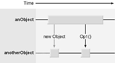
Figure A-8. UML interaction sequence diagram (shown on its side, a style you'll see used throughout this book).
EAN: N/A
Pages: 148