8.1 Common Architectures for Communications Equipment
|
|
Communications devices can differ significantly in their form factors-for example, a cell phone is several times smaller than the telecommunications switch through which its calls may be switched. The following is a partial list of the popular forms for communications devices, along with some examples:
-
Host-based adapter-a PCI Ethernet add-on card
-
A handheld device-a cell phone or pager
-
A 'pizza box' design-a single processor or multi-processor switch or router
-
A chassis-based design-a CompactPCI-based voice or data switch
Of these, the pizza box and the chassis designs are the most popular for communications devices in a network. The pizza box design is typically a single-board architecture with one or more processors. The chassis-based design has multiple boards plugged into a backplane which provides the communication among the boards.
8.1.1 Single-Board Designs
A single-board/single-processor architecture is the simplest design. Here, both the control and data planes run on the only processor or CPU. In several cases, data plane acceleration could be provided by a hardware device, like a switching chipset (an ASIC). In these cases, hardware acceleration devices do not run software-they are only configured by the software running on the central processor. An exception is the network processor, which typically runs microcode downloaded from the central processor.
The second type of architecture is the single-board/multi-processor architecture. The simplest example is the two-processor architecture, in which the control and management code run on Processor 1, and the data plane and services run on Processor 2, all on the same board. This separation isolates the core function of the system (data plane) from control and management functions.
Consider the case of a Layer 3 switch (IPS) with two processors. Processor 1 runs RIP, OSPF, the SNMP Agent, and the CLI Agent. Processor 2 runs the forwarding function services, like NAT and Firewall, with support from the hardware. Packets will first be processed in Processor 2 and dispatched to Processor 1 if they are targeted towards the control plane or management plane (as represented by the routing protocol tasks and management agents). Processor 2 will communicate with Processor 1 using Inter-Processor Communication very similar to communication in a single-processor system. Also, a segment of memory can be shared between these two processors and used for data exchange between them.
The two-processor example can be extended to include multiple processors, all on the same board. Or, the board can possess slots to permit add-on cards. Each of these add-on boards can have a processor and use proprietary mechanisms to communicate with the base board. The PCI Mezzanine Card (PMC) is a variation on this concept. The PMC is added parallel to the main board in a PMC slot.
8.1.2 Chassis-Based Designs
The most general form of multi-processor architecture is the use of multiple boards in a single chassis. An example of a popular architecture in communications is CompactPCI, specified by the PCI Industrial Computers Manufacturing Group (PICMG). The first version of this specification used the PCI electrical specifications in an industrial form factor and the PCI bus for inter-card communication. Follow-on specifications like PICMG 2.16 included a packet switching architecture for inter-card communications.
Variations of this design include addition of a H.110 Time Division Multiplexing (TDM) or PICMG 2.15 bus for carrying circuit-switched traffic. So, the same multi-service design (data + voice) may have a packet-switched interconnect for data and a H.110 bus for carrying TDM traffic. A design with a packet-switched backplane and H.110 bus is shown in xrefparanum.
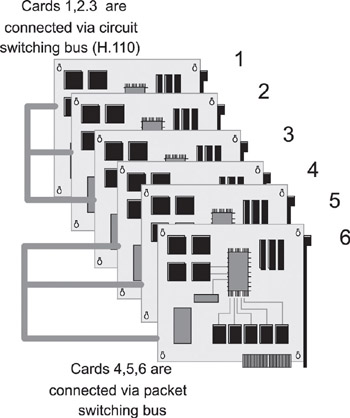
Figure 8.1: Chassis design with packet + circuit switched buses.
The isolation between the TDM and packet traffic is required because TDM traffic requires a guaranteed delay, which is achieved by using fixed slots on the H.110 bus for passing the voice traffic between the transport cards. Similar to the software model of control and data traffic between tasks, multi-board systems typically use different transport mechanisms for control and data (or payload) traffic. In a chassis based router, it is quite common for the control traffic to use a different transport than the payload. The PCI bus is one example of a control interconnect. Fast Ethernet (100 Mbps) or Gigabit Ethernet (1 Gbps) are also used in some systems for control traffic within the chassis.
8.1.3 Rack-Based Designs
Variations on the pizza box- and chassis-based designs find application in rack environments. It is quite common to find router or switch devices with a 1U or 2U form factor mounted in a rack (see Figure 8.2).
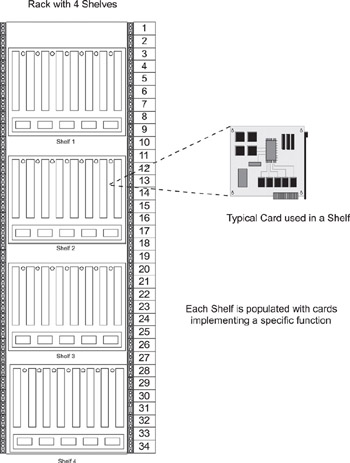
Figure 8.2: A multiple-card rack design.
A rack is a standard cabinet used for mounting servers, network gear, storage, or other components in a complete solution. Hardware vendors use the standard sizes when building any hardware that is intended to be rack mounted. Racks are designed as empty cabinets with rails for mounting equipment, and often racks are designed to handle the electrical and thermal requirements of specific applications by including power supplies and cooling fans inside the cabinet.
Each rack can house multiple devices-the height of which is expressed as a U form factor, or 1.75 inches high for each U. Cabinets (racks) can contain 42U or more, depending on the application and environmental requirements. A high-density server may contain several CPUs but take up only 1U (1.75 inches) in a cabinet. CompactPCI cards are often positioned vertically and require several Us, depending on the architecture. For example, a common configuration for a large system is a rack with multiple shelves, each shelf housing multiple cards, as shown in xrefparanum. Each shelf can be considered to be a single system or a subsystem, depending upon the complexity of the communications device. A computing or communications solution can also occupy more than one rack unit, as shown in Figure 8.3.
The connections between the individual cards can be through a backplane or a midplane architecture. The backplane architecture indicates that each card is of the full 15.5 inches in depth, while the midplane architecture implies that each card has a depth of 7.75 inches. The system can be expanded by using fiber optic cable between the individual racks. Protocols, several of them proprietary, have been developed for the inter-card communication.
|
|
EAN: 2147483647
Pages: 126