Dissecting a Typical Communications Session
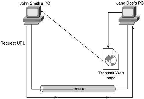
| A "typical communications session" is a vague phrase that almost defies description. Depending on where you work and what technologies have been implemented, the typical network can have seemingly infinite variety. For the sake of example, let's assume that our network consists of Ethernet LANs that communicate via the TCP/IP protocol suite. We'll dissect this communications session within this technical context to better appreciate the active role of IP addresses. We'll use a simple example throughout this chapter to demonstrate how the various network components interact and culminate in a successful communications session. The example uses Hypertext Transfer Protocol (HTTP) to access the website of a nearby host. An ExampleIt's sometimes difficult to remember that there are other communications protocols besides TCP/IP. The successful commercialization of the Internet has made TCP/IP so ubiquitous as to make all other communications protocols seem superfluous. Given that the title of this book is IP Addressing Fundamentals, we'll limit our discussion of "a typical communications session" to IP. A scan of desktop settings reveals all sorts of IP and IP-like addresses. Some of these numbers include the computer's own IP address, a Domain Name System (DNS), default gateway, and subnet mask. All this information is provided via an IP address, range of IP addresses, or IP-based mask and is intended to facilitate communications using that protocol. That shouldn't be too surprising. The surprise comes when you stop to think about the layers of communications protocols in a "typical" communications session. Each layer requires its own addressing system. The TCP protocol suite uses protocol-specific addresses called port numbers to identify specific applications per host. IP uses numeric machine-level addresses to identify endpoint devices on a network. Also, LANs typically use physical machine addresses that are burned into the firmware of their interface cards to uniquely identify endpoint devices. To make matters worse, humans tend not to like using IP addresses. Instead, they vastly prefer human-friendly mnemonics such as www.mycompany.com in order to reach their own website, or jane.doe@mycompany.com to send an e-mail message to a coworker. Each of these examples of a mnemonic address represents a completely different paradigm for networked computing. That's symptomatic of networked computing in general. Networked applications have matured to the point that applications follow no single paradigm. Given that caveat, we'll use a simple HTTP example to demonstrate the key concepts presented in this chapter. In our example, a human (John Smith) manipulates the keyboard of his desktop computer to view the website on a colleague's (Jane Doe) desktop computer. Their respective HTTP utilities appear to be communicating directly with each other to facilitate this transfer of web content. This perception is known as logical adjacency. Figure 10-1 depicts a somewhat abstract perspective of what happens in this sample communications session. Figure 10-1. The Logical Perspective: John Smith Accesses Jane Doe's Website, www.jane.doe.mycompany.com
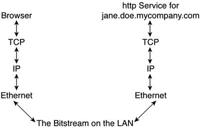
Layers of ProtocolsSo much for the logical perspective. Now let's consider what really happens by investigating the various layers of protocols that interoperate in support of a communications session. The communications session in our example uses HTTP. That protocol must reside on both devices in order for the session to be successful. Both devices must be able to communicate with each other, which means they need a network interconnecting them, as well as a networking protocol. The next thing we need is an address, or the two computers won't know how to reach each other. John Smith is the one who initiates the session, so he must have the correct address. The address of Jane's website is www.janedoe.mycompany.com. This address is known as a uniform resource locator (URL). The URL is actually several bundled addresses. www is the name of specific web content, which is typically accessed using HTTP. That utility uses TCP's well-known port 80. In other words, it corresponds to an application-level address. The next portion, janedoe, is the name of a host within the mycompany.com domain. Logically, because janedoe is a host, it must have a unique IP address. That address is created from the IP network address block assigned to mycompany.com. This nested series of addresses might initially appear to be everything you need to get the communications session going. You have an application port number, a machine name, and a domain name. But that's still not enough. Application-level addresses are valid only at the application level. That might sound a bit trite, but think about it. Even the most sophisticated and powerful software can't function without support from other mechanisms such as a network. Thus, you must conclude that the URL is really only an indirect means of identifying an addressee, not the last piece of information that is required to complete the delivery. If you stop to think about that for a while, you will realize that some means of correlating indirect application-level addresses with network-level addresses must exist. Otherwise, networked applications would have a very tough time functioning properly. Figure 10-2 takes the simple topology of a web-browsing session and dissects it into its functional layers. This helps you better appreciate the sequence of events that are requisite to a successful communications session. Figure 10-2. The Layered Perspective: John Smith Accesses Jane Doe's Website, www.jane.doe.mycompany.com
This session requires reliable delivery of data and uses the TCP/IP communications protocol suite. That protocol suite consists of two sets of protocols, with each set focused on different functions. TCP stands for Transmission Control Protocol. IP stands for Internet Protocol. It is a lower-layer suite of protocols responsible for getting data through networks. TCP works in conjunction with IP. Each set of protocols is responsible for different, but highly compatible, functions. That shouldn't be too surprising, especially when you consider that they were made for each other. TCP, generally speaking, focuses on interactions with applications, including handling application data, and preparing that data for transport via IP. IP, generally speaking, focuses on getting packetized application data to the stipulated destination. Thus, IP is more network-oriented than application-oriented. NOTE TCP isn't the only suite of protocols designed for use with IP. Other classes of protocols include User Datagram Protocol (UDP) and Internet Control Message Protocol (ICMP). Although they are not quite as visible as TCP (and, consequently, are not as well-known), both UDP and ICMP are critical components of the comprehensive suite of communications protocols that has come to be known generically as TCP/IP, or simply IP. But merely encapsulating data for transport across a network isn't equivalent to transporting it across a network. Thus, IP must rely on other mechanisms for transmission and local delivery. These mechanisms are provided courtesy of a LANEthernet in this example. This example nicely exhibits the interaction of the IP address space with other mechanisms both above and below it in the stack of communications protocols. We'll come back to this example and use it to demonstrate the interactions and correlative mechanisms that regulate hand-offs between the stacked protocols. NOTE The phrase "stack of communications protocols" implies two concepts:
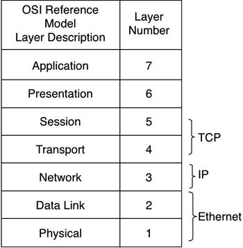
Given these two points, it seems logical that a reliable mechanism, or set of mechanisms, is required to track the correlation between all these addresses. More importantly, you need to keep them synchronized in an environment that can be highly dynamic. The best way to explain this is to introduce, or reintroduce, the concept of a model that maps out the logical sequence of events in a communications session. It seems as if every communications protocol has its own model to explain how it works. We'll use the ubiquitous seven-layer Open Systems Interconnect (OSI) Reference Model. The OSI Reference ModelThe International Organization for Standardization (or ISO, as it prefers to be called) regulates global standards for a wide variety of technologies. When it comes to data communications, ISO tends to embrace and adopt standards established at either the national level (such as the American National Standards Institute [ANSI]) or the industry level. Consequently, the ISO isn't regarded as a powerhouse authority in any one field. Perhaps its greatest contribution to the field of data communications is its reference model that describes the sequence of events that are prerequisite to a successful data communications session. The OSI Reference Model, shown in Figure 10-3, organizes all the requisite steps in a data communications session into seven layers that dictate the necessary sequence of events. Included in this figure is how TCP/IP and Ethernet fit into the model. This helps make the stacking relationship between these protocols more clear. Figure 10-3. The OSI's Seven-Layer Reference Model as It Relates to Commonly-Used Network Protocols
As is evident in Figure 10-3, TCP correlates loosely with Layers 4 and 5 and is responsible for interfacing with networked applications such as e-mail and HTTP. IP is distinctly a Layer 3 protocol. It provides all the mechanisms and functions necessary to transport application data across networks. All varieties and speeds of Ethernet occupy Layers 1 and 2. All these layers (and functions) are necessary to support a communications session. The way they interoperate to form the logical adjacency between peer processes is simple: Data is passed from one layer to the next and, typically, is encapsulated. To illustrate this point, an application passes data to TCP. The TCP suite of protocols segments the data into more manageable chunks for transport across the network. Each chunk is numbered so that data can be put back into the proper order at its destination. Each data chunk is also given an application address (a port number) so that it can be delivered to the proper application. The TCP data segments are then passed on to IP. IP wraps the segments with packets. Packets bear the IP address of both the source and the destination machines engaged in the communications session. But packets are a Layer 3 construct, not a Layer 2 mechanism, so they must be handed off to a Layer 2 protocol for further processing. In this case, Ethernet accepts the IP packets and encapsulates them with a frame. The frame must also use source and destination addresses, but those are MAC addresses, not IP addresses. This structure can be transmitted one bit at a time on the LAN. NOTE TCP is the "reliable" transport protocol used in conjunction with IP. Being a reliable protocol isn't easy. It means that you have to guarantee not only that IP packets get to their destination, but also that they can be put back together in the right order after they arrive. To do all this, TCP relies on features such as sequence numbers and delivery acknowledgments. Such features are not necessarily a trait you find in all Layer 4 transport protocols. When the data arrives at its intended destination, the encapsulation process is reversed. The Ethernet network interface card strips off the frame to reveal the IP packet entombed within. It then hands off that packet to IP. IP then removes the IP packet to reveal the TCP segment. The segment is passed on to the appropriate application based on the port number indicated in the segment's header. The net effect is that each layered mechanism logically appears to be communicating with its peer process on the other machine it is communicating with. Identifying the Points of TranslationFrom the preceding discussion of logical adjacency, it should be somewhat obvious that there are a number of points at which a handoff is made between two dissimilar protocols or technologies. Identifying these points of translation is the first step in understanding them. The two key points at which translation must occur are
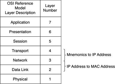
Figure 10-4 shows where these translations occur in the stack of communications protocols. Figure 10-4. Points of Translation Relative to the OSI's Seven-Layer Reference Model
These two translation functions are performed through separate mechanisms. Mnemonic names are translated into IP addresses via DNS. IP addresses are translated into MAC addresses through Address Resolution Protocol (ARP). We'll look at how each works throughout the remainder of this chapter. |
EAN: 2147483647
Pages: 118