NAS Connectivity Architecture: Hardware
| |
Bus connectivity for the NICs become proprietary as they attach through the I/O adapters of the NAS server bus. Most vendors adhere to the PCI standard; however, this is difficult to determine without specific inquiries to the vendor. This becomes an important aspect given that the number of transactions supported depends on the performance of the NICs and their respective bus interfaces.
NAS and LAN Topologies
The following discussion illustrates the various LAN topologies where NAS configurations are installed. Each offers a set of challenges and considerations, and in order to effectively understand these, we offer a summary overview of LAN fundamentals.
Understanding the fundamentals of network hardware devices is important to how the NAS solutions will perform in any network topology. Network connectivity devices such as bridges, hubs, routers, and switches operate at specific levels of the OSI reference network model while performing their duties . As you may recall, the OSI network model forms the layers for TCP/IP processing. The most important layers to consider for network devices are the physical access layer (layer 1), the datalink layer, (layer 2), the network layer (layer 3), and the transport layer (layer 4). They are depicted in Figure 12-1 and described below through their connection proximity and processing responsibilities.
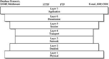
Figure 12-1: OSI Layersfrom the physical to the transport
-
The Physical Layer (Layer 1) The physical layer provides the direct mechanical and electrical connection to the network media (the wires and cabling that sends the data in bits throughout its physical interconnections). Layer 1 interfaces directly with the data link layer through the media access control (MAC) sublayer.
-
The Datalink Layer (Layer 2) The datalink layer separates the transmitted data into frames for transmission over the physical media, such as 10 base T5, 10 base T2 cable, or UTP wiring. This layer performs error-checking and is responsible for retransmitting frames. It provides a direct channel to the network layer through a logical link control (LLC) sublayer and a lower sublayer which connects to the transmission media called the media access control layer (MAC).
-
The Network Layer (Layer 3) The network layer provides information on the routing of data transmitted from sender to receiver. This layer ecncapsulates the user data through routable network protocols such as, IP, IPX, SNA, or AppleTalk.
-
The Transport Layer (Layer 4) The transport layer provides information on how a point-to-point connection is developed. Layer 4 utilizes the network layer to determine the type of connection between computers. This is based upon TCP or UDP protocols. These two connections set up sessions between computers, and determine the protocol under which they will operate. However, it should be noted that TCP is a connection-oriented protocol while UDP is connectionless, which characterizes their performance and error recovery. This facilitates the use of Remote Procedure Calls between operating systems (refer to RPCs in Chapter 11).
Using the OSI model, network devices operate using layers 1 through 3 to develop a local area network (LAN). The network devices used to leverage each layer of the OSI model in building a campus network or LAN is diverse, sometimes interchangeable, and can be confusing if you are inexperienced in network administration and management. However, they are illustrated in Figure 12-2 and categorized into the following segments.
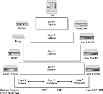
Figure 12-2: Network devices and their corresponding OSI layer
-
Repeaters, Concentrators, and Hubs Although most are becoming obsolete given the evolution of LAN switching devices, many still exist, and all operate at the physical level. Repeaters provide a retransmission of signals in order to increase the range of physical segments of wiring. They continue to be used to extend the physical distance capabilities of LAN wiring segments. Concentrators and hubs provide the same servicesthat is, the connection of clients and servers through one wiring segment. This results in all servers, PCs, and workstations on the segment sharing the bandwidth and forming a single collision domain, as it relates to the machine access layer (MAC) algorithms that use the Ethernet Carrier Sense Access/Collision Detection (CSMA/CD) protocol.
-
Bridges and Layer 2 Switches Bridges interconnect different types of physical network topologies such as FDDI, Ethernet, and token ring, and operate at layer 2: the data link layer. They also can be responsible for filtering network traffic using the layer 2 MAC addresses. Layer 2 switches connect different port connections and enable the transfer of data by destination address. They are commonly used to provide a backbone network connection where clients can reach servers outside their domain and interconnect to outside WAN services.
-
Routers and Layer 3 Switches Routers or layer 3 switches forward data packets based upon IP address, link, or network availability and performance. Layer 3 switches perform similar functions as routers. They provide this service from two distinct architectures, both operating under layer 3 information. Port switches operate at the hardware level of the switch by directing network traffic from port to port according to layer 3 information. They also perform at chip speeds. The follow-on from port switches are frame switches that operate from layer-3 information; however, they perform port traffic direction by examining the data packet and providing the most effective routing to the destination.
-
Layer 4 Switch These switches make connection decisions based on information in layer 4 regarding session and application layer information. This allows them to provide such services as load balancing across servers and broadcast services.
We can view the placement of NAS devices within two major topologies: appliance placement and enterprise placement. Appliance placement facilitates the placement of data as close to the user as possible. This requires the placement of an NAS device within a hub or single-network segment. The enterprise placement provides greater access to data through multiple segments of the network. Given the variability of the network designs and topologies, there are many ways of implementing these configurations. We will discuss these two major approaches and their related considerations.
NAS Network Deployment
To discuss the NAS deployment in as much context as possible, we offer a typical network infrastructure, as illustrated in Figure 12-3. This conceptual network supports a theoretical business that is populated with a headquarters staff within a three-story building, and a data center which is housed in a separate building. The business is externally connected to the Internet and outside leased lines. External sales and marketing personnel utilize the network through Internet connectivity and servers connected through outside dedicated leased lines. This conceptual network does not illustrate particular topologies, but is designed to represent major components that will both influence and pose deployment challenges to NAS devices.
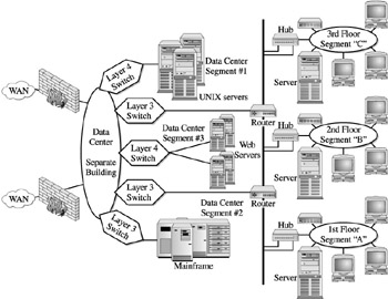
Figure 12-3: A typical network infrastructure
As mentioned previously, there are two categories of deployment: appliance level and enterprise level. Although derived by various requirements, including the network infrastructure, initial deployment decisions center on data ownership and access. This means the user community may feel they own the data, such as an accounting and finance department, and have characteristics of homogeneous access (in other words, only persons within the accounting department can access the information).
Another perspective is data that becomes developed from multiple sources and accessed by multiple user communities. Often characterized by marketing and sales departments that utilize multiple sources to build data bases, data access profiles become very complex. User access can be on multiple levels (say, for sales people, executives, and order-entry administrators), and therefore requests for data may traverse multiple network segments. More importantly, answer sets tend to move through multiple network segments.
Yet another view of external access within the data center comes from using combinations of homogeneous and heterogeneous access. The most obvious are facilities that store web-based data for access to companies outside sales personnel, partners , and customers. An important aspect of this data placement is, of course, security; however, data integrity and availability is paramount as well.
NAS Appliance Network Deployment Given our typical company, lets analyze the homogeneous access of data. This type of access and data placement easily justifies the appliance level of NAS solution. A subset of our large network infrastructure is illustrated in Figure 12-4, where the Accounting department has installed an NAS appliance, and access is contained within the network segment handling the first floor. Note that this segment is configured with a hub that provides a connection between the PCs and workstations used in the finance department, as well as the main server handling the finance client/server financial applications. The NAS device handles the I/O load of the financial application server and performs very well as long as the traffic is contained with the network segment.
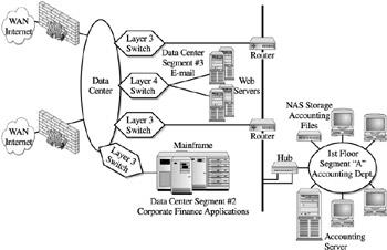
Figure 12-4: The network segment supporting Accounting
The challenges and performance issues begin to show up as users from other network segments begin to access the NAS device. Outside users degrade service by adding additional traffic that is serviced by a hub device which must share its bandwidth within the network segment. Secondly, as users outside the network segment access the NAS accounting data, they must traverse several jumps from one network segment to another. These are referred to as hops. The more hops the more network latency is built up, adding to aggregate traffic on the network backbone.
Finally, the type of I/O workload also determines the placement factors and, more importantly, the required bandwidth for network segments and the capacities of network devices. Consider our example of the accounting data. One reason this works well is the financial planning data thats used within this area. These worksheets can be extremely large and I/O-intensive as they are processed by the financial application server. The answer sets and results of these financial planning programs are extremely I/O- intensive , however, when handled within the limits of the hub and configured connections (for instance, multiple ports for the server and multiple ports for the NAS device).
NAS Enterprise Network Deployment Certainly, not all data access is contained within a network segment. As a matter of fact, many corporate applications must be accessed through the data center. Figure 12-5 shows the network segments within the data center. This portrays a more complex set of segments than the local user networks. Considering that the data center must support multiple user access, applications, and data, its requirements for network segmentation become comprehensive. If we add external access to the Internet as well as dedicated leased lines, the network infrastructure becomes the focal point for corporate data access and makes data placement a more daunting task.
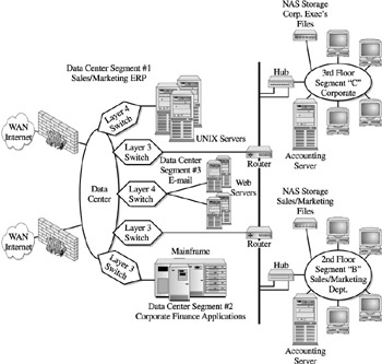
Figure 12-5: Network segments within the data center
Lets take our example of sales and marketing data that must be accessed by multiple users, and which is then developed from multiple data sources, both internal and external. Although this is also a good candidate for NAS solution, placement and capacities become key to a successful implementation. Without restating discussions that will be covered in Part V, lets assume that the sales and marketing data have the following characteristics.
-
Sales Data Sales orders, tracking, and customer information are contained in the ERP system, which is processed and accessed through the UNIX servers within the data center. Data access is handled by sales administration through the third-floor network segment, outside sales people from the web sites, and finally by limited users that work in branch offices and access the ERP system through the dedicated leased lines.
-
Marketing Data Marketing information, product information, brochures , market analysis, and data mart analysis are contained in every system in the data center, the mainframe, the UNIX servers, and the web servers. The information used to build market and customer analysis data marts are copied from sales orders, customers, customer tracking, and products.
Two solutions are productive in these situations. First, is the use of NAS devices for the collection and storage of web data. Second, is a large NAS device to hold the sales data that is accessed by sales personnel in the field. An additional important installation would be the use of NAS devices to hold large data base tables that make up the marketing datamart (for example, market and customer analysis data). Each of these solutions can be placed within the data center for general access. Given that the data center connects to the network backbone and contains a secondary network backbone within the data center (as shown in Figure 12-3), the bandwidth to handle multiple user access can be configured with high-speed network resources and devices.
Although on the surface it may appear that the installation of these large NAS devices should be on the data center backbone, when we look closer at the networks makeup , we find that each segment within the data center is handled by a layer 3 layer 4 switch. Each of these devices provides additional flexibility in the placement of NAS devices given their I/O responsibility. For example, the NAS sales data device could be placed within the UNIX segment given the network access from both internal and external users. The NAS device could be placed within the web segment given that access, security, and sourcing can be managed with existing web workloads. (We placed a layer 4 switch in our example shown in Figure 12-5; this could leverage workload balancing effectively, however, from a newer layer 5 switching device.)
NAS over WAN Topologies
Part of our discussion has touched on network challenges and various issues with LAN topologies. However, as Figure 12-5 shows, there are outside network connections that influence various NAS configurations, along with their placement and opportunities. Each configuration discussed earlier offers a set of challenges and considerations which effectively utilize WAN connections.
To facilitate this understanding, we offer a summary overview of WAN and LAN-WAN fundamentals. Figure 12-6 shows the external connections from the data center into the outside world. There are two major types depicted, Internet connections and dedicated leased-line connections. The Internet connections are leased lines that attach to an Internet service provider (ISP) where additional connections provide external Internet accesses . These lines are dedicated and depend on the grade and capacity of the line, the capacity and resources of the ISP, and the type of service the company has contracted for. In any event, it is outside the control of the NAS device and internal network infrastructure. Basically, you have to deal with what you have available, in Internet terms.
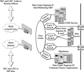
Figure 12-6: WAN connectivity options
The second external connection is through dedicated lease lines that are available through the long distance carrier, IXC, and local exchange LXC carrier. They provide dedicated lines and services through a wide variety of telecommunications transport technologies that include frame relays, ATMs, and other communications protocols. Actually, once it leaves the confines of the data center, the data being transferred is within the control and management of the IXC or LXC, which could mean, and usually does mean, multiple communications protocols, circuits, and equipment. Basically, you have to deal with what you have available, in long distance and local carrier terms, same as the Internet.
The point is that when you leave the data center and transmit data either through a myriad of Internet connections and equipment or the IXC and LXC set of circuits and equipment, it is out of your control. This requires that you compensate for each of these conditions and deploy the NAS devices with due consideration for the issues of each. Essentially, these are areas of security and recoverability. Given that you are dependent on the availability of specific communications vendors as well as bandwidth and service levels from these local and long distance vendors, your confidence and history with vendor services should drive your deployment choices.
From the NAS perspective, there are two considerations for deployment that facilitate access and data placement. These are access to data from the remote branch locations that require application access and specific services of the data center. Secondly, the ability to provide levels of application and data recoverability in a disaster recovery scenario is a major consideration for remote offices. Each of these deployments utilizes dedicated leased lines. These solutions are depicted in Figure 12-7, where a NAS device is deployed within the data center attached to the data center backbone that the remote offices utilize to back up their data. This is followed by a more complex deployment where production NAS devices hold sales and order data which are mirrored into a disaster recovery site where a similar NAS device holds the synchronized data.
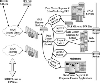
Figure 12-7: NAS deployment using WAN connections
The second D/R deployment employs the ability to utilize RAID level 1 functions of the NAS devices to provide an asynchronous link between the data center NAS device and the D/R site NAS device (see Figure 12-7). This solution utilizes an asynchronous update process that does not require the production NAS device to wait or hold I/O processing before the D/R site commits to writing the same data. The setup compensates for the availability and reliability factors within the WAN connection to minimize disruption with production processing.
The backup deployment for the remote sites is less complex and, although performed in an asynchronous manner, is generally done at night on an automated basis. Backup processes are run at the remote sites that transfer copies or backups to the NAS backup device attached to the data center network backbone in order to facilitate the greatest level of bandwidth and throughput as possible (see Figure 12-5). This compensates for the WAN connection being consumed during the daytime with user transaction traffic and minimizes the disruption of production processing within the data center during prime usage.
Internet access is the other major category for NAS placement that has WAN effectsalthough in many cases it is secondary given the typical placement of the NAS device. NAS provides an excellent solution for the storage of web files that are dynamically created through user access to web servers. In Figure 12-7, our theoretical company provides web servers that link to the outside world through a firewall and then switch to the ISP. The ISP then supports global connectivity to the root servers of the Internet, sometimes referred to as the 13 root servers. This connection enables the global communications that allow data to flow in and out of the web servers. Consequently, this becomes a critical point for managing traffic access and security with which the NAS devices become integrated.
In any event, the WAN access as it comes in from the Web is in the form of presentation layer commands, or HTTP requests. However, the resolution of IP addresses, and then subsequent network and computer addresses, are provided by the switch connected to the ISP circuits; this is often called an edge switch. Given the transmission of packets from the edge switch, additional direction is provided, vis- -vis our example in Figure 12-7 through the layer 4 switch where load balancing is facilitated to balance access among the web servers. Finally, the redirection will take place to initiate the file I/O to the appropriate NAS storage device.
Figure 12-8 illustrates this in more detail. The importance of the transmission path plays an important role in the placement of the NAS devices within the data center segment. More importantly, placement within the subsegment provides additional functionality with handling the type of traffic that may be expected with web access. Our example also points out that there is a scalable path for growth as both web servers and associated NAS storage devices will undoubtedly grow within the network segment in conjunction with the network itself (in other words, as web access grows, network bandwidth needs increase along with layer 3 and layer 4 switching and the need for NAS storage). Given NAS placement in this scenario, the NAS boxes follow a logical path that is associated with related network infrastructure components.
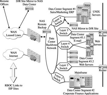
Figure 12-8: TCP/IP considerations for NAS deployment
| |
EAN: 2147483647
Pages: 192
- Using SQL Data Manipulation Language (DML) to Insert and Manipulate Data Within SQL Tables
- Performing Multiple-table Queries and Creating SQL Data Views
- Writing External Applications to Query and Manipulate Database Data
- Working with Ms-sql Server Information Schema View
- Exploiting MS-SQL Server Built-in Stored Procedures