Internal Storage -- The Details
This section covers system catalogs and the internal data storage of tables. Although you can use SQL Server effectively without understanding the internals, understanding the details of how SQL Server stores data will help you develop efficient applications. (If you don't need this in-depth information, you can skip this discussion and proceed to the section on indexes.)
When you create a table, one or more rows are inserted into a number of system catalogs to manage that table. At a minimum, rows are added to the sysobjects , sysindexes , and syscolumns system catalogs (tables). When you define the new table with one or more constraints, rows are added to the sysreferences and sysconstraints system tables.
For every table created, a single row that contains ”among other things ”the name , object ID, and owner of the new table is added to the sysobjects table. The sysindexes table will gain a single row that contains pointers to the first data page that the new table uses and information regarding the table's size , including the number of pages and rows currently being used. The syscolumns table will gain one row for each column in the new table, and each row will contain information such as the column name, datatype, and length. Each column receives a column ID, which directly corresponds to the order in which you specified the columns when you created the table. That is, the first column listed in the CREATE TABLE statement will have a column ID of 1, the second column will have a column ID of 2, and so on. Figure 6-3 shows the rows added to the sysobjects , sysindexes , and syscolumns system tables when you create a table. (Not all columns are shown for each table.)
Notice in the syscolumns output in the figure that the xoffset column contains negative numbers in some rows. (Ignore the offset column. It's used only to store row structure information for older versions of SQL Server.) Any column that contains variable-length data will have a negative xoffset value in syscolumns . The negative numbers are assigned to the variable-length columns in decreasing order (-1, -2, -3, and so on) in the order in which the column is specified in the CREATE TABLE statement. You can see in Figure 6-3 that the employee last name ( emp_lname ) is the first variable-length column in the table.
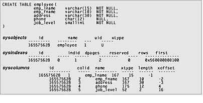
Figure 6-3. Catalog information stored after creating a table.
Data Pages
Data pages are the structures that contain all of a table's nontext and image data. As with all other types of pages in SQL Server, data pages have a fixed size of 8 KB, or 8192 bytes. Data pages consist of three major components : the page header, data rows, and the row offset array, as shown in Figure 6-4.
Page Header
As you can see in Figure 6-4, the page header occupies the first 96 bytes of each data page (leaving 8096 bytes for data and row offsets). Table 6-2 shows the information contained in the page header.
Data Rows
Following the page header is the area in which the table's actual data rows are stored. The maximum size of a single data row is 8096 bytes. A data row can't span multiple pages (except for nontext and image columns, which are stored in their own separate pages). The number of rows stored on a given page will vary depending on the structure of the table and on the data being stored. A table that has all fixed-length columns will always store the same number of rows per page; variable-length rows will store as many rows as will fit based on the actual length of the data entered. Keeping row length compact allows more rows to fit on a page, thus reducing I/O and improving the cache-hit ratio.
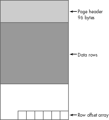
Figure 6-4. The structure of a data page.
Table 6-2. Information contained in the page header.
| Field | Contains |
|---|---|
| pageID | File number and page number of this page in the database. |
| nextPage | File number and page number of the next page, if this page is in a page chain. |
| prevPage | File number and page number of the previous page, if this page is in a page chain. |
| objID | ID of the object to which this page belongs. |
| lsn | Log sequence number (LSN) value used for changes and updates to this page. |
| slotCnt | Total number of slots used on this page. |
| level | Level of this page in an index (always 0 for leaf pages). |
| indexId | Index ID of this page (always 0 for data pages). |
| freeData | Byte offset of the first free space on this page. |
| pminlen | Number of bytes in fixed-length portion of rows. |
| freeCnt | Number of free bytes on page. |
| reservedCnt | Number of bytes reserved by all transactions. |
| xactreserved | Number of bytes reserved by the most recently started transaction. |
| tornBits | 1 bit per sector for detecting torn page writes (discussed in Chapter 5). |
| flagBits | 2-byte bitmap that contains additional information about the page. |
Row Offset Array
The row offset array is a block of 2-byte entries, each of which indicates the offset on the page on which the corresponding data row begins. Every row has a 2-byte entry in this array, and these 2 bytes were included in the discussion in "Variable-Length vs. Fixed-Length Datatypes" in which we mentioned the 10 overhead bytes needed by every row. Although these bytes aren't stored in the row with the data, they do impact the number of rows that will fit on a page.
The row offset array indicates the logical order of rows on a page. For example, if a table has a clustered index, SQL Server will store the rows in the order of the clustered index key. This doesn't mean that the rows will be physically stored on the page in the order of the clustered index key, but that slot 0 in the offset array will refer to the first row in the order, slot 1 will refer to the second row, and so forth. As we'll see shortly when we examine an actual page, the offset of these rows can be anywhere on the page.
There's no internal global row number for every row in a table. You can use the combination of page number and slot number on the page to uniquely identify each row in a table.
Examining Data Pages
You can view the contents of a data page by using the DBCC PAGE statement, which allows you to view the page header, data rows, and row offset table for any given data page in a database. (Only a system administrator can use DBCC PAGE.) But because you typically won't need to view the content of a data page, you won't find much about DBCC PAGE in the SQL Server documentation. Nevertheless, in case you want to use it, here's the syntax:
DBCC PAGE ( { dbid dbname }, filenum , pagenum [, printopt ] [, cache ] ) |
The DBCC PAGE command includes the parameters shown in Table 6-3. Figure 6-5 shows sample output from DBCC PAGE. Note that DBCC TRACEON (3604) instructs SQL Server to return the results to the client instead of to the error log, as is the default for many of the DBCC commands that deal with internals issues.
Table 6-3. Parameters of the DBCC PAGE command.
| Parameter | Description | |
|---|---|---|
| dbid | ID of the database containing the page. | |
| dbname | Name of the database containing the page. | |
| filenum | File number containing the page. | |
| pagenum | Page number within the file. | |
| printopt | Optional print option; takes one of these values: | |
| Default; print the buffer header and page header. | ||
| 1 | Print the buffer header, page header, each row separately, and the row offset table. | |
| 2 | Print the buffer and page headers, page as a whole, and the offset table. | |
| cache | Optional; location of page; takes one of these values: | |
| Print the page as found on disk. | ||
| 1 | Default; print the page as found in cache (if it resides in cache); otherwise , retrieve and print the page from disk. | |
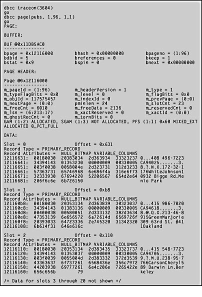
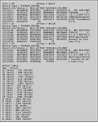
Figure 6-5. Sample output from DBCC PAGE.
As you can see, the output from DBCC PAGE is divided into four main sections: Buffer, Page Header, Data, and Offset Table (really the Offset Array). The Buffer section shows information about the buffer for the given page. (A buffer in this context is an in-memory structure that manages a page.)
The Page Header section in Figure 6-5 displays the data for all the header fields on the page. (Table 6-2 shows the meaning of most of these fields.) The Data section contains information for each row. For each row, DBCC PAGE indicates the slot position of the row and the offset of the row on the page. The page data is then divided into three parts . The left column indicates the byte position within the row where the displayed data occurs. The next four columns contain the actual data stored on the page, displayed in hexadecimal. The right column contains a character representation of the data. Only character data will be readable in this column, although some of the other data might be displayed.
The Offset Table section shows the contents of the row offset array at the end of the page. In the figure, you can see that this page contains 23 rows, with the first row (indicated by slot 0) beginning at offset 1585 (0x631). The first row physically stored on the page is actually row 6, with an offset in the row offset array of 96. DBCC PAGE displays the rows in slot number order, even though, as you can see by the offset of each of the slots, that isn't the order in which the rows physically exist on the page.
Structure of Data Rows
A table's data rows have the general structure shown in Figure 6-6. The data for all fixed-length columns is stored first, followed by the data for all variable-length columns. Table 6-4 shows the information stored in eachrow.
Status Bits A contains a bitmap indicating properties of the row. The bits have the following meaning:
- Bit 0 Versioning information; in SQL Server 7, it's always 0.
- Bits 1 through 3 Taken as a 3-bit value, 0 indicates a primary record, 1 indicates a forwarded record, 2 indicates a forwarded stub, 3 indicates an index record, 4 indicates a blob fragment, 5 indicates a ghost index record, and 6 indicates a ghost data record. (We'll discuss forwarding and ghost records in Chapter 8.)
- Bit 4 Indicates that a NULL bitmap exists; in SQL Server 7, a NULL bitmap is always present, even if no NULLs are allowed in any column.
- Bit 5 Indicates that variable-length columns exist in the row.
- Bits 6 and 7 Not used in SQL Server 7.
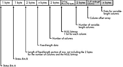
Figure 6-6. The structure of data rows.
Within each block of fixed-length or variable-length data, the data is stored in the column order in which the table was created. For example, suppose a table is created with the following statement:
CREATE TABLE Test1 (Col1 int NOT NULL, Col2 char(25) NOT NULL, Col3 varchar(60) NULL, Col4 money NOT NULL, Col5 varchar(20) NOT NULL) |
The fixed-length data portion of this row would contain the data for Col1 , followed by the data for Col2 , followed by the data for Col4 . The variable-length data portion would contain the data for Col3 , followed by the data for Col5 . For rows that contain only fixed-length data, the following is true:
- The first hexadecimal digit of the first byte of the data row will be 1, indicating that no variable-length columns exist. (The first hexadecimal digit is comprised of bits 4 through 7; bits 6 and 7 are always 0, and if no variable-length columns exist, bit 5 is also 0. Bit 4 is always 1, so the value of the four bits is displayed as 1.)
- The data row ends after the NULL bitmap, which follows the fixed-length data. (That is, the shaded portion shown in Figure 6-6 won't exist in rows with only fixed-length data.)
- The total length of every data row will be the same.
Table 6-4. Information stored in a table's data rows.
| Information | Mnemonic | Size |
|---|---|---|
| Status Bits A | TagA | 1 byte |
| Status Bits B (not used in SQL Server 7) | TagB | 1 byte |
| Fixed-length size | Fsize | 2 bytes |
| Fixed-length data | Fdata | Fsize - 4 |
| Number of columns | Ncol | 2 bytes |
| NULL bitmap (1 byte for each column in table; a 1 indicates that the corresponding column is NULL) | Nullbits | Ceiling (Ncol / 8) |
| Number of variable-length columns | VarCount | 2 bytes |
| Variable column offset array | VarOffset | 2 * VarCount |
| Variable-length data | VarData | VarOff[VarCount] - (fsize + 4 + Ceiling (Ncol / 8) + 2 * VarCount) |
Column Offset Array
A data row that has all fixed-length columns has no variable column count or column offset array . A data row that has variable-length columns has a column offset array in the data row with a 2-byte entry for each variable-length column, indicating the position within the row where each column ends. (The terms offset and position aren't exactly interchangeable. Offset is 0-based, and position is 1-based. A byte at an offset of 7 is in the eighth byte position in the row.)
Storage of Fixed-Length and Variable-Length Rows
Two examples follow that illustrate how fixed-length and variable-length data rows are stored. First, the simpler case of an all fixed-length row:
CREATE TABLE Fixed (Col1 char(5) NOT NULL, Col2 int NOT NULL, Col3 char(3) NULL, Col4 char(6) NOT NULL, Col5 float NOT NULL) |
When this table is created, the following row (or one very much like it) is inserted into the sysindexes system table:
id name indid first minlen ----------- ----- ------ -------------- ------ 1797581442 Fixed 0 0xC70000000100 30 |
And these rows are inserted into the syscolumns system table:
name colid xtype length xoffset ---- ------ ----- ------ ------- Col1 1 175 5 4 Col2 2 56 4 9 Col3 3 175 3 13 Col4 4 175 6 16 Col5 5 62 8 22 |
For tables containing only fixed-length columns, the minlen value in sysindexes will be equal to the sum of the column lengths (from syscolumns . length ), plus 4 bytes. It won't include the 2 bytes for the number of columns, or the bytes for the null bitmap.
To look at a specific data row in this table, first insert a new row:
INSERT Fixed VALUES ('ABCDE', 123, null, 'CCCC', 4567.8) |
Figure 6-7 shows this row's actual contents on the data page. To run the DBCC PAGE command, we had to take the value of first from the syindexes output above (0xC70000000100) and convert it to a file and page address. In hexadecimal notation, each set of two characters represents a byte. We first had to swap the bytes to get 00 01 00 00 00 C7. The first two groups represent the 2-byte file number, and the last four groups represent the page number. So the file is 0x0001, which is 1, and the page number is 0x000000C7, which is 199 in decimal.
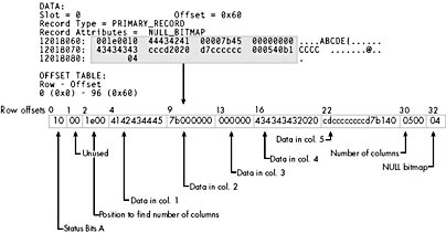
Figure 6-7. A data row containing all fixed-length columns (header not shown).
NOTE
The sysindexes table contains three columns that represent page numbers within a database: first , firstIAM , and root . Each is stored in a byte-swapped format. To convert to a decimal file number and page number, you must first swap the bytes and then convert the values from hexadecimal to decimal. You could use the Windows calculator to do the conversion. However, a script has been provided on the companion CD to create a stored procedure called ConvertPageNums , which will convert all these columns in the sysindexes table for you.
WARNING
Version 7 of SQL Server does not guarantee that the sysindexes.first column will also indicate the first page of a table. We have found that first is reliable until you begin to perform deletes and updates on the data in the table.
Reading the output takes a bit of practice. DBCC PAGE displays the data rows in groups of 4 bytes at a time. Within each group of four, the bytes are listed in reverse order. So the first group of four bytes is byte 3, byte 2, byte 1, and byte 0. The shaded area in the figure has been expanded to show the bytes in the actual byte-number sequence.
The first byte is Status Bits A, and its value (0x10) indicates that only bit 4 is on, so the row has no variable-length columns. The second byte in the row remains unused. The third and fourth bytes (1e00) indicate the length of the fixed-length fields, which is also the column offset in which the Ncol value can be found. (The byte-swapped value is 0x001e, which translates to 30.) You can identify the data in the row for each column simply by using the offset value in the syscolumns table: the data for column Col1 begins at offset 4, the data for column Col2 begins at offset 9, and so on. As an int , the data in Col2 (7b000000) must be byte-swapped to give us the value 0x0000007b, which is equivalent to 123 in decimal.
Note that the 3 bytes of data for Col3 are all zeros, representing an actual NULL in the column. Because the row has no variable-length columns, the row ends 3 bytes after the data for column Col5 . The 2 bytes starting right after the fixed-length data at offset 30 (0500, which is byte-swapped to yield 0x0005) indicate that five columns are in the row. The last byte is the NULL bitmap. The value of 4 means that only the third bit is on, because in our row, the third column was indeed a NULL.
WARNING
Fixed-length columns always use the full number of bytes defined for the table, even if the column holds a NULL value. If you've used previous versions of SQL Server, this might take you by surprise. We know of at least one large database at a manufacturing company that expanded to three or four times its size when upgraded to version 7. This is because they had fields in many tables defined as char(255) and allowing NULLs. Some tables had 10 or more such columns, and the vast majority of the data was actually NULL. However, in SQL Server 7, every one of these columns needed a full 255 bytes of storage and the database ballooned in size!
Here's the somewhat more complex case of a table with variable-length data. Each row has three varchar columns:
CREATE TABLE Variable (Col1 char(3) NOT NULL, Col2 varchar(250) NOT NULL, Col3 varchar(5) NULL, Col4 varchar(20) NOT NULL, Col5 smallint NULL) |
When you create this table, the following row is inserted into the sysindexes system table:
id name indid first minlen ----------- -------- ------ -------------- ------ 1333579789 Variable 0 0xC90000000100 9 |
And these rows are inserted into the syscolumns system table:
name colid xtype length xoffset ---- ------ ----- ------ ------- Col1 1 175 3 4 Col2 2 167 250 -1 Col3 3 167 5 -2 Col4 4 167 20 -3 Col5 5 52 2 7 |
Now insert a row into the table:
INSERT Variable VALUES ('AAA', REPLICATE('X',250), NULL, 'ABC', 123) |
The REPLICATE function is used here to simplify populating a column; this function builds a string of 250 X s to be inserted into Col2 .
As shown in Figure 6-8, the data for the fixed-length columns is located using the offset value in syscolumns . In this case, Col1 begins at offset 4, and Col5 begins at offset 7.
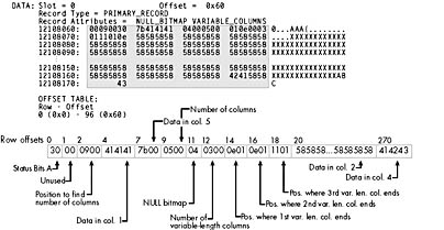
Figure 6-8. A data row with variable-length columns (header not shown).
To find the variable-length columns, first locate the column offset tables in the row. Right after the 2-byte field indicating the total number of columns (0500), and the NULL bitmap with the value 0x04, a 2-byte field exists with the value 0x0300 (or 3, decimal) indicating that three variable-length fields exist. Next comes the column offset array. Three 2-byte values indicate the ending position of each of the three variable-length columns: 0e01 is byte-swapped to 0x010e, so the first variable byte column ends at position 270. The next 2-byte offset is also 0e01, so that column has no length and has nothing stored in the variable data area. (Unlike fixed-length fields, if a variable-length field has a NULL value, it takes no room in the data row. SQL Server distinguishes between a varchar containing NULL and an empty string by determining whether the bit for the field is 0 or 1 in the NULL bitmap.) The third 2-byte offset is 1101, which, when byte-swapped, gives us 0x0111. This means the row ends at position 273 (and is a total of 273 bytes in length).
The total storage space needed for a row depends on a number of factors. Variable-length fields add additional overhead to a row, and their actual size is probably unpredictable. Even for fixed-length fields, the number of bytes of overhead can change depending on the number of columns in the table. In the earlier example pertaining to Figure 6-1, we mentioned that 10 bytes of overhead existed if a row contained all fixed-length columns. For that row, 10 is the correct number. The size of the NULL bitmap needs to be long enough to store a bit for every column in the row. In the Figure 6-1 example, the table had 11 columns, so the NULL bitmap needed to be 2 bytes. In the examples illustrated by Figures 6-7 and 6-8, the table had only 5 columns, so the NULL bitmaps needs only a single byte. Don't forget that the total row overhead also needs to include the 2 bytes for each row in the offset table at the bottom of the page.
Page Linkage
Unlike earlier versions of SQL Server, SQL Server 7 doesn't connect the individual data pages of a table in a doubly linked list unless the table has a clustered index. All levels of indexes are linked together, and since the data is considered the leaf level of a clustered index, SQL Server does maintain the linkage. However, for a heap, there is no such linked list connecting the pages to each other. The only way that SQL Server determines which pages belong to a table is by inspecting the IAMs for the table.
If the table has a clustered index, you can use the M_nextPage and M_prevPage values in the page header information to determine the ordering of pages in the list. Alternatively, you can use the DBCC EXTENTINFO command to get a list of all the extents that belong to an object. This example uses the Orders table in the Northwind database:
dbcc extentinfo ('Northwind', 'Orders', 1 ) |
The last argument indicates only extents for index 1, which is the clustered index (and includes the data). Here is the output:
file_id page_id pg_alloc ext_size obj_id index_id avg_used ----------- ----------- ----------- ----------- ----------- -------- -------- 1 143 1 1 357576312 1 25 1 145 1 1 357576312 1 25 1 291 1 1 357576312 1 25 1 292 1 1 357576312 1 25 1 293 1 1 357576312 1 25 1 294 1 1 357576312 1 25 1 295 1 1 357576312 1 25 1 296 1 1 357576312 1 25 1 304 8 8 357576312 1 25 1 328 5 8 357576312 1 25 |
Notice that the first eight rows indicate an extent size ( ext_size ) of 1. As discussed in Chapter 5, the first eight pages of a table are allocated from mixed extents. Only after the table has reached eight pages does SQL Server allocate uniform extents of eight pages each. The last two rows in the table show this situation, and the page number ( page_id ) column gives the page number of the first page of the extent. Note that the last extent (starting on page 328) has used only five of its pages at this time.
Text and Image Data
As mentioned earlier, if a table contains text or image data, the actual data isn't stored on the data pages with the rest of the data for a row. Instead, SQL Server stores a 16-byte pointer in the data row that indicates where the actual data can be found. In SQL Server 7, individual text , ntext , and image pages aren't limited to holding data for only one occurrence of a text , ntext , or image column. A text , ntext , or image page can hold data from multiple columns and from multiple rows; the page can even have a mix of text , ntext , and image data. One text or image page can hold only text or image data from a single table.
Text or image data is stored in a collection of 8-KB pages that aren't necessarily located next to each other. In SQL Server 7, the pages are logically organized in a B-tree structure, while in earlier versions of SQL Server, pages were linked together in a page chain. The advantage of the SQL Server 7 method is that operations starting in the middle of the string are more efficient. SQL Server 7 can quickly navigate the tree, while earlier versions of SQL Server had to scan through the page chain. The structure of the B-tree differs slightly depending on whether the amount of data is less than or more than 32 KB. (See Figure 6-9 for the general structure.) We'll discuss B-trees in more detail in the next section of the chapter.
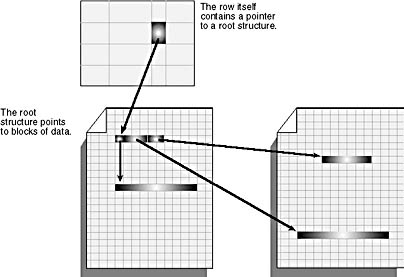
Figure 6-9. A text column pointing to a B-tree that contains the blocks of data.
If the amount of data is less than 32 KB, the text pointer in the data row points to an 84-byte text root structure. This forms the root node of the B-tree structure. The root node points to the blocks of text or image data. While the data for text , ntext , and image columns is arranged logically in a B-tree, physically both the root node and the individual blocks of data are spread throughout the text , ntext , and image pages for the table. They're placed wherever space is available. The size of each block of data is determined by the size written by an application. Small blocks of data will be combined to fill a page. If the amount of data is less than 64 bytes, it's all stored in the root structure.
If the amount of data for one occurrence of a text or image column exceeds 32 KB, SQL Server starts building intermediate nodes between the data blocks and the root node. The root structure and the data blocks are interleaved throughout the text and image pages in the same manner as described earlier. The intermediate nodes, however, are stored in pages that aren't shared between occurrences of text or image columns. Each page storing intermediate nodes contains only intermediate nodes for one text or image column in one data row.
EAN: 2147483647
Pages: 144
- Chapter I e-Search: A Conceptual Framework of Online Consumer Behavior
- Chapter IV How Consumers Think About Interactive Aspects of Web Advertising
- Chapter VI Web Site Quality and Usability in E-Commerce
- Chapter XIII Shopping Agent Web Sites: A Comparative Shopping Environment
- Chapter XV Customer Trust in Online Commerce