IO Processing
Now that we've covered the structure and types of drivers and the data structures that support them, let's look at how I/O requests flow through the system. I/O requests pass through several predictable stages of processing. The stages vary depending on whether the request is destined for a device operated by a single-layered driver or for a device reached through a multilayered driver. Processing varies further depending on whether the caller specified synchronous or asynchronous I/O, so we'll begin our discussion of I/O types with these two then move on to others.
Types of I/O
Applications have several options for the I/O requests they issue. For example, they can specify synchronous or asynchronous I/O, I/O that maps a device's data into the application's address space for access via application virtual memory rather than I/O APIs, and I/O that transfers data between a device and noncontiguous application buffers in a single request. Furthermore, the I/O manager gives the drivers the choice of implementing a shortcut I/O interface that can often mitigate IRP allocation for I/O processing. In this section, we'll explain each of these I/O variations.
Synchronous I/O and Asynchronous I/O
Most I/O operations that applications issue are synchronous; that is, the application waits while the device performs the data transfer and returns a status code when the I/O is complete. The program can then continue and access the transferred data immediately. When used in their simplest form, the Win32 ReadFile and WriteFile functions are executed synchronously. They complete an I/O operation before returning control to the caller.
Asynchronous I/O allows an application to issue an I/O request and then continue executing while the device transfers the data. This type of I/O can improve an application's throughput because it allows the application to continue with other work while an I/O operation is in progress. To use asynchronous I/O, you must specify the FILE_FLAG_OVERLAPPED flag when you call the Win32 CreateFile function. Of course, after issuing an asynchronous I/O operation, the thread must be careful not to access any data from the I/O operation until the device driver has finished the data transfer. The thread must synchronize its execution with the completion of the I/O request by monitoring a handle of a synchronization object (whether that's an event object, an I/O completion port, or the file object itself) that will be signaled when the I/O is complete.
Regardless of the type of I/O request, internally, I/O operations represented by IRPs are performed asynchronously; that is, once an I/O request has been initiated, the device driver returns to the I/O system. Whether or not the I/O system returns immediately to the caller depends on whether the file was opened for synchronous or asynchronous I/O. Figure 9-20 illustrates the flow of control when a read operation is initiated. Notice that if a wait is done, which depends on the overlapped flag in the file object, it is done in kernel mode by the NtReadFile function.
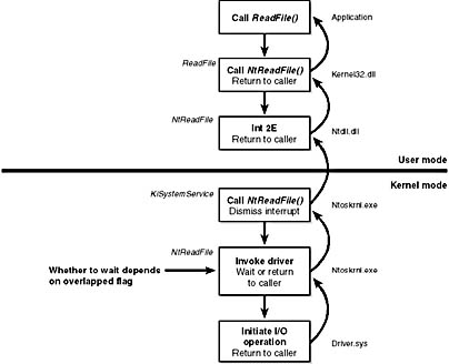
Figure 9-20 Control flow for an I/O operation
You can test the status of a pending asynchronous I/O with the Win32 HasOverlappedIoCompleted function. If you're using I/O completion ports, you can use the GetQueuedCompletionStatus function.
Fast I/O
Fast I/O is a special mechanism that allows the I/O system to bypass generating an IRP and instead go directly to the file system driver or cache manager to complete an I/O request. (Fast I/O is described in detail in Chapters 11 and 12.) A driver registers its fast I/O entry points by entering them in a structure pointed to by the PFAST_IO_DISPATCH pointer in its driver object.
EXPERIMENT
Looking at a Driver's Registered Fast I/O RoutinesThe !drvobj kernel debugger command can list the fast I/O routines that a driver registers in its driver object. However, typically only file system drivers have any use for fast I/O routines. The following output shows the fast I/O table for the NTFS file system driver object:
Fast I/O routines: FastIoCheckIfPossible be3263ef Ntfs!NtfsPostUsnChange+0xd8c FastIoRead be31869e Ntfs!NtfsCreateInternalStreamCommon+0x1b43 FastIoWrite be318df9 Ntfs!NtfsCreateInternalStreamCommon+0x229e FastIoQueryBasicInfo be3020fa Ntfs!NtfsRaiseStatus+0x105a8 FastIoQueryStandardInfo be317d1e Ntfs!NtfsCreateInternalStreamCommon+0x11c3 FastIoLock be32622d Ntfs!NtfsPostUsnChange+0xbca FastIoUnlockSingle be326139 Ntfs!NtfsPostUsnChange+0xad6
The output shows that NTFS has registered its NtfsPostUsnChange routine as the fast I/O table's FastIoCheckIfPossible entry. As the name of this fast I/O entry implies, the I/O manager sometimes calls this function before issuing a fast I/O request, giving a driver an opportunity to indicate when fast I/O operations on a file are not feasible.
Mapped File I/O and File Caching
Mapped file I/O is an important feature of the I/O system, one that the I/O system and the memory manager produce jointly. (See Chapter 7 for details on how mapped files are implemented.) Mapped file I/O refers to the ability to view a file residing on disk as part of a process's virtual memory. A program can access the file as a large array without buffering data or performing disk I/O. The program accesses memory, and the memory manager uses its paging mechanism to load the correct page from the disk file. If the application writes to its virtual address space, the memory manager writes the changes back to the file as part of normal paging.
Mapped file I/O is available in user mode through the Win32 CreateFileMapping and MapViewOfFile functions. Within the operating system, mapped file I/O is used for important operations such as file caching and image activation (loading and running executable programs). The other major consumer of mapped file I/O is the cache manager. File systems use the cache manager to map file data in virtual memory to provide better response time for I/O-bound programs. As the caller uses the file, the memory manager brings accessed pages into memory. Whereas most caching systems allocate a fixed number of bytes for caching files in memory, the Windows 2000 cache grows or shrinks depending on how much memory is available. This size variability is possible because the cache manager relies on the memory manager to automatically expand (or shrink) the size of the cache, using the normal working set mechanisms explained in Chapter 7. By taking advantage of the memory manager's paging system, the cache manager avoids duplicating the work that the memory manager already performs. (The workings of the cache manager are explained in detail in Chapter 11.)
Scatter/Gather I/O
Windows 2000 also supports a special kind of high-performance I/O that is called scatter/gather, available via the Win32 ReadFileScatter and WriteFileGather functions. These functions allow an application to issue a single read or write from more than one buffer in virtual memory to a contiguous area of a file on disk. To use scatter/gather I/O, the file must be opened for noncached I/O, the user buffers being used have to be page-aligned, and the I/Os must be asynchronous (overlapped). Furthermore, if the I/O is directed at a mass storage device, the I/O must be aligned on a device sector boundary and have a length that is a multiple of the sector size.
I/O Request to a Single-Layered Driver
This section traces a synchronous I/O request to a single-layered kernel-mode device driver. Handling a synchronous I/O to a single-layered driver consists of seven steps:
- The I/O request passes through a subsystem DLL.
- The subsystem DLL calls the I/O manager's NtWriteFile service.
- The I/O manager allocates an IRP describing the request and sends it to the driver (a device driver in this case) by calling its own IoCallDriver function.
- The driver transfers the data in the IRP to the device and starts the I/O operation.
- The driver signals I/O completion by interrupting the CPU.
- When the device completes the operation and interrupts the CPU, the device driver services the interrupt.
- The driver calls the I/O manager's IoCompleteRequest function to inform it that it has finished processing the IRP's request, and the I/O manager completes the I/O request.
These seven steps are illustrated in Figure 9-21.
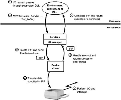
Figure 9-21 Queuing and completing a synchronous request
Now that we've seen how an I/O is initiated, let's take a closer look at interrupt processing and I/O completion.
Servicing an Interrupt
After an I/O device completes a data transfer, it interrupts for service and the Windows 2000 kernel, I/O manager, and device driver are called into action. Figure 9-22 illustrates the first phase of the process. (Chapter 3 describes the interrupt dispatching mechanism, including DPCs. We've included a brief recap here because DPCs are key to I/O processing.)
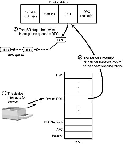
Figure 9-22 Servicing a device interrupt (phase 1)
When a device interrupt occurs, the processor transfers control to the kernel trap handler, which indexes into its interrupt dispatch table to locate the ISR for the device. ISRs in Windows 2000 typically handle device interrupts in two steps. When an ISR is first invoked, it usually remains at device IRQL only long enough to capture the device status and then stop the device's interrupt. It then queues a DPC and exits, dismissing the interrupt. Later, when the DPC routine is called, the device finishes processing the interrupt. When that's done, the device calls the I/O manager to complete the I/O and dispose of the IRP. It might also start the next I/O request that is waiting in the device queue.
The advantage of using a DPC to perform most of the device servicing is that any blocked interrupt whose priority lies between the device IRQL and the DPC/dispatch IRQL is allowed to occur before the lower-priority DPC processing occurs. Intermediate-level interrupts are thus serviced more promptly than they otherwise would be. This second phase of an I/O (the DPC processing) is illustrated in Figure 9-23.
Completing an I/O Request
After a device driver's DPC routine has executed, some work still remains before the I/O request can be considered finished. This third stage of I/O processing is called I/O completion and is initiated when a driver calls IoCompleteRequest to inform the I/O manager that it is through processing the request specified in the IRP (and the stack location that it owns). The steps I/O completion entails vary with different I/O operations. For example, all the I/O services record the outcome of the operation in an I/O status block, a data structure the caller supplies. Similarly, some services that perform buffered I/O require the I/O system to return data to the calling thread.
In both cases, the I/O system must copy some data that is stored in system memory into the caller's virtual address space. If the IRP completed synchronously, the caller's address space is current and directly accessible, but if the IRP completed asynchronously, the I/O manager must delay IRP completion until it can access the caller's address space. To gain access to the caller's virtual address space, the I/O manager must transfer the data "in the context of the caller's thread,"—that is, while the caller's thread is executing (which means that caller's process is the current process and has its address space active on the processor). It does so by queuing a kernel-mode asynchronous procedure call (APC) to the thread. This process is illustrated in Figure 9-24.
As explained in Chapter 3, APCs execute in the context of a particular thread, whereas a DPC executes in arbitrary thread context, meaning that the DPC routine can't touch the user-mode process address space. Remember too that DPCs have a higher software interrupt priority than APCs.
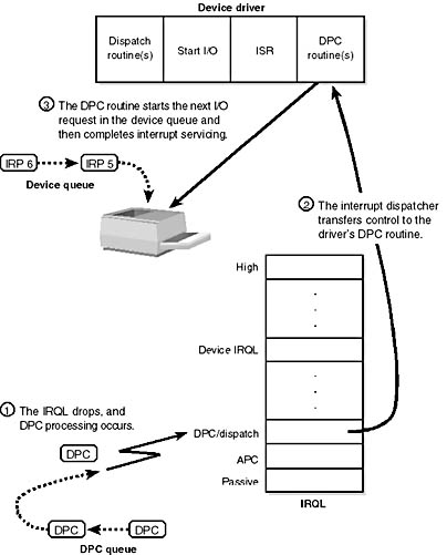
Figure 9-23 Servicing a device interrupt (phase 2)
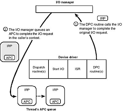
Figure 9-24 Completing an I/O request (phase 1)
The next time that thread begins to execute at low IRQL, the pending APC is delivered. The kernel transfers control to the I/O manager's APC routine, which copies the data (if any) and the return status into the original caller's address space, frees the IRP representing the I/O operation, and sets the caller's file handle (and any caller-supplied event or I/O completion port) to the signaled state. The I/O is now considered complete. The original caller or any other threads that are waiting on the file (or other object) handle are released from their waiting state and readied for execution.
Figure 9-25 illustrates the second stage of I/O completion.
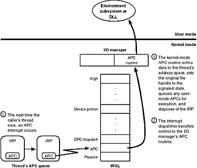
Figure 9-25 Completing an I/O request (phase 2)
A final note about I/O completion: the asynchronous I/O functions ReadFileEx and WriteFileEx allow a caller to supply a user-mode APC as a parameter. If the caller does so, the I/O manager queues this APC to the caller's thread APC queue as the last step of I/O completion. This feature allows a caller to specify a subroutine to be called when an I/O request is completed or canceled. User-mode APC completion routines execute in the context of the requesting thread and are delivered only when the thread enters an alertable wait state (such as calling the Win32 SleepEx, WaitForSingleObjectEx, or WaitForMultipleObjectsEx function).
I/O Requests to Layered Drivers
The preceding section showed how an I/O request to a simple device controlled by a single device driver is handled. I/O processing for file-based devices or for requests to other layered drivers happens in much the same way. The major difference is, obviously, that one or more additional layers of processing are added to the model.
Figure 9-26 shows how an asynchronous I/O request travels through layered drivers. It uses as an example a disk controlled by a file system.
Once again, the I/O manager receives the request and creates an I/O request packet to represent it. This time, however, it delivers the packet to a file system driver. The file system driver exercises great control over the I/O operation at that point. Depending on the type of request the caller made, the file system can send the same IRP to the disk driver or it can generate additional IRPs and send them separately to the disk driver.
The file system is most likely to reuse an IRP if the request it receives translates into a single straightforward request to a device. For example, if an application issues a read request for the first 512 bytes in a file stored on a floppy disk, the FAT file system would simply call the disk driver, asking it to read one sector from the floppy disk, beginning at the file's starting location.
To accommodate its reuse by multiple drivers in a request to layered drivers, an IRP contains a series of IRP stack locations (not to be confused with the stack used by threads to store function parameters and return addresses). These data areas, one for every driver that will be called, contain the information that each driver needs in order to execute its part of the request—for example, function code, parameters, and driver context information. As Figure 9-26 illustrates, additional stack locations are filled in as the IRP passes from one driver to the next. You can think of an IRP as being similar to a stack in the way data is added to it and removed from it during its lifetime. However, an IRP isn't associated with any particular process, and its allocated size doesn't grow and shrink. The I/O manager allocates an IRP from one if its IRP look-aside lists or nonpaged system memory at the beginning of the I/O operation.
After the disk driver finishes a data transfer, the disk interrupts and the I/O completes, as shown in Figure 9-27.
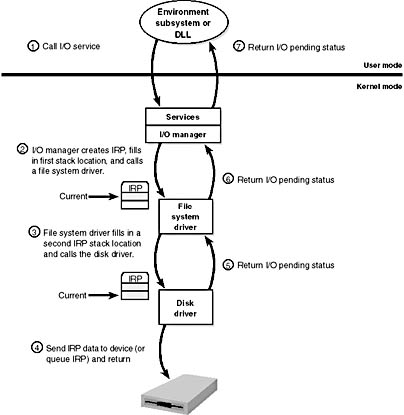
Figure 9-26 Queuing an asynchronous request to layered drivers
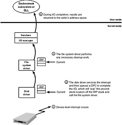
Figure 9-27 Completing a layered I/O request
As an alternative to reusing a single IRP, a file system can establish a group of associated IRPs that work in parallel on a single I/O request. For example, if the data to be read from a file is dispersed across the disk, the file system driver might create several IRPs, each of which reads some portion of the request from a different sector. This queuing is illustrated in Figure 9-28.
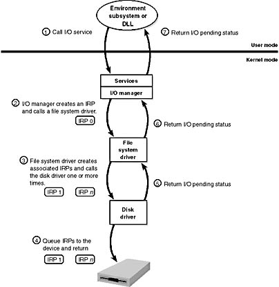
Figure 9-28 Queuing associated IRPs
The file system driver delivers the associated IRPs to the device driver, which queues them to the device. They are processed one at a time, and the file system driver keeps track of the returned data. When all the associated IRPs complete, the I/O system completes the original IRP and returns to the caller, as shown in Figure 9-29.
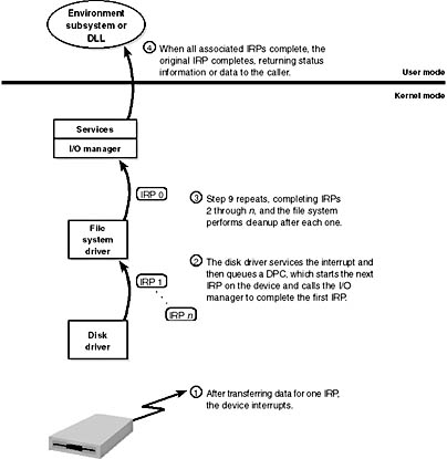
Figure 9-29 Completing associated IRPs
NOTE
All Windows 2000 file system drivers that manage disk-based file systems are part of a stack of drivers that is at least three layers deep: the file system driver sits at the top, a volume manager in the middle, and a disk driver at the bottom. In addition, any number of filter drivers can be interspersed above and below these drivers. For clarity, the preceding example of layered I/O requests includes only a file system driver and a disk device driver. See Chapter 10, on storage management, for more information.
I/O Completion Port Operation
Win32 applications create completion ports by calling the Win32 API CreateIoCompletionPort and specifying a NULL completion port handle. This results in the execution of the NtCreateIoCompletion system service. The executive's IoCompletion object is based on the kernel synchronization object called a queue. Thus, the system service creates a completion port object and initializes a queue object in the port's allocated memory. (A pointer to the port also points to the queue object because the queue is at the start of the port memory.) A queue object has a concurrency value that is specified when a thread initializes one, and in this case the value that is used is the one that was passed to CreateIoCompletionPort. KeInitializeQueue is the function that NtCreateIoCompletion calls to initialize a port's queue object.
When an application calls CreateIoCompletionPort to associate a file handle with a port, the NtSetInformationFile system service is executed with the file handle as the primary parameter. The information class that is set is FileCompletionInformation, and the completion port's handle and the CompletionKey parameter from CreateIoCompletionPort are the data values. NtSetInformationFile dereferences the file handle to obtain the file object and allocates a completion context data structure.
Finally, NtSetInformationFile sets the CompletionContext field in the file object to point at the context structure. When an asynchronous I/O operation completes on a file object, the I/O manager checks to see whether the CompletionContext field in the file object is non-NULL. If it is, the I/O manager allocates a completion packet and queues it to the completion port by calling KeInsertQueue with the port as the queue on which to insert the packet. (Remember that the completion port object and queue object are synonymous.)
When a server thread invokes GetQueuedCompletionStatus, the system service NtRemoveIoCompletion is executed. After validating parameters and translating the completion port handle to a pointer to the port, NtRemoveIoCompletion calls KeRemoveQueue.
As you can see, KeRemoveQueue and KeInsertQueue are the engines behind completion ports. They are the functions that determine whether a thread waiting for an I/O completion packet should be activated. Internally, a queue object maintains a count of the current number of active threads and the maximum number of active threads. If the current number equals or exceeds the maximum when a thread calls KeRemoveQueue, the thread will be put (in LIFO order) onto a list of threads waiting for a turn to process a completion packet. The list of threads hangs off the queue object. A thread's control block data structure has a pointer in it that references the queue object of a queue that it's associated with; if the pointer is NULL, the thread isn't associated with a queue.
Windows 2000 keeps track of threads that become inactive because they block on something other than the completion port by relying on the queue pointer in a thread's control block. The scheduler routines that possibly result in a thread blocking (such as KeWaitForSingleObject, KeDelayExecutionThread, and so on) check the thread's queue pointer. If the pointer isn't NULL, the functions call KiActivateWaiterQueue, a queue-related function that decrements the count of active threads associated with the queue. If the resultant number is less than the maximum and at least one completion packet is in the queue, the thread at the front of the queue's thread list is awakened and given the oldest packet. Conversely, whenever a thread that is associated with a queue wakes up after blocking, the scheduler executes the function KiUnwaitThread, which increments the queue's active count.
Finally, the PostQueuedCompletionStatus Win32 API function results in the execution of the NtSetIoCompletion system service. This function simply inserts the specified packet onto the completion port's queue by using KeInsertQueue.
Figure 9-30 shows an example of a completion port object in operation. Even though two threads are ready to process completion packets, the concurrency value of 1 allows only one thread associated with the completion port to be active, and so the two threads are blocked on the completion port.
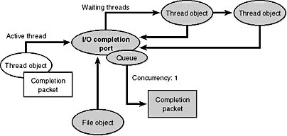
Figure 9-30 I/O completion port operation
Synchronization
Drivers must synchronize their access to global driver data and hardware registers for two reasons:
- The execution of a driver can be preempted by higher-priority threads and time-slice (or quantum) expiration or can be interrupted by interrupts.
- On multiprocessor systems, Windows 2000 can run driver code simultaneously on more than one processor.
Without synchronization, corruption could occur—for example, because device driver code running at a passive IRQL when a caller initiates an I/O operation can be interrupted by a device interrupt, causing the device driver's ISR to execute while its own device driver is already running. If the device driver was modifying data that its ISR also modifies, such as device registers, heap storage, or static data, the data can become corrupted when the ISR executes. Figure 9-31 illustrates this problem.
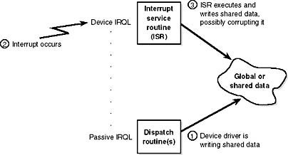
Figure 9-31 Queuing an asynchronous request to layered drivers
To avoid this situation, a device driver written for Windows 2000 must synchronize its access to any data that the device driver shares with its ISR. Before attempting to update shared data, the device driver must lock out all other threads (or CPUs, in the case of a multiprocessor system) to prevent them from updating the same data structure.
The Windows 2000 kernel provides special synchronization routines that device drivers must call when they access data that their ISRs also access. These kernel-synchronization routines keep the ISR from executing while the shared data is being accessed. On a single CPU system, these routines raise the IRQL to a specified level before updating a structure. On a multiprocessor system, however, because a driver can execute on two or more processors at once, this technique isn't enough to block other accessors. Therefore, another mechanism, a spinlock, is used to lock a structure for exclusive access from a particular CPU. (Spinlocks are explained in the section "Kernel Synchronization" in Chapter 3.)
By now, you should realize that although ISRs require special attention, any data that a device driver uses is subject to being accessed by the same device driver running on another processor. Therefore, it's critical for device driver code to synchronize its use of any global or shared data (or any accesses to the physical device itself). If the ISR uses that data, the device driver must use kernel-synchronization routines; otherwise, the device driver can use a kernel spinlock.
EAN: 2147483647
Pages: 121
- Chapter II Information Search on the Internet: A Causal Model
- Chapter VI Web Site Quality and Usability in E-Commerce
- Chapter VII Objective and Perceived Complexity and Their Impacts on Internet Communication
- Chapter VIII Personalization Systems and Their Deployment as Web Site Interface Design Decisions
- Chapter XV Customer Trust in Online Commerce