IO Data Structures
Four primary data structures are associated with I/O requests: file objects, driver objects, device objects, and I/O request packets (IRPs). Each of these structures is defined in the DDK header file Ntddk.h as well as in the DDK documentation. You can display each of them with the kernel debugger by using the !file, !drvobj, !devobj, and !irp commands.
File Objects
File objects are the kernel-mode constructs for handles to files or devices. File objects clearly fit the criteria for objects in Windows 2000: they are system resources that two or more user-mode processes can share, they can have names, they are protected by object-based security, and they support synchronization. Although most shared resources in Windows 2000 are memory-based resources, most of those that the I/O system manages are located on physical devices or represent actual physical devices. Despite this difference, shared resources in the I/O system, like those in other components of the Windows 2000 executive, are manipulated as objects. (See Chapter 3 for a description of the object manager and Chapter 8 for information on object security.)
File objects provide a memory-based representation of resources that conform to an I/O-centric interface, in which they can be read from or written to. Table 9-4 lists some of the file object's attributes. For specific field declarations and sizes, see the structure definition for FILE_OBJECT in Ntddk.h.
Table 9-4 File Object Attributes
| Attribute | Purpose |
|---|---|
| Filename | Identifies the physical file that the file object refers to |
| Current byte offset | Identifies the current location in the file (valid only for synchronous I/O) |
| Share modes | Indicate whether other callers can open the file for read, write, or delete operations while the current caller is using it |
| Open mode flags | Indicate whether I/O will be synchronous or asynchronous, cached or noncached, sequential or random, and so on |
| Pointer to device object | Indicates the type of device the file resides on |
| Pointer to the volume parameter block (VPB) | Indicates the volume, or partition, that the file resides on |
| Pointer to section object pointers | Indicates a root structure that describes a mapped file |
| Pointer to private cache map | Identifies which parts of the file are cached by the cache manager and where they reside in the cache |
When a caller opens a file or a simple device, the I/O manager returns a handle to a file object. Figure 9-9 illustrates what occurs when a file is opened.
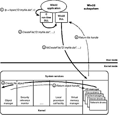
Figure 9-9 Opening a file object
In this example, (1) a C program calls the run-time library function fopen, which in turn (2) calls the Win32 CreateFile function. The Win32 subsystem DLL (in this case, Kernel32.dll) then (3) calls the native NtCreateFile function in Ntdll.dll. The routine in Ntdll.dll contains the appropriate instruction to cause a transition into kernel mode to the system service dispatcher, which then (4) calls the real NtCreateFile routine in Ntoskrnl.exe. (See Chapter 3 for more information about system service dispatching.)
Like other executive objects, file objects are protected by a security descriptor that contains an access-control list (ACL). The I/O manager consults the security subsystem to determine whether the file's ACL allows the process to access the file in the way its thread is requesting. If it does, (5,6) the object manager grants the access and associates the granted access rights with the file handle that it returns. If this thread or another thread in the process needs to perform additional operations not specified in the original request, the thread must open another handle, which prompts another security check. (See Chapter 8 for more information about object protection.)
Because a file object is a memory-based representation of a shareable resource and not the resource itself, it's different from other executive objects. A file object contains only data that is unique to an object handle, whereas the file itself contains the data or text to be shared. Each time a thread opens a file handle, a new file object is created with a new set of handle-specific attributes. For example, the current byte offset attribute refers to the location in the file at which the next read or write operation using that handle will occur. Each handle to a file has a private byte offset even though the underlying file is shared. A file object is also unique to a process, except when a process duplicates a file handle to another process (by using the Win32 DuplicateHandle function) or when a child process inherits a file handle from a parent process. In these situations, the two processes have separate handles that refer to the same file object.
Although a file handle might be unique to a process, the underlying physical resource is not. Therefore, as with any shared resource, threads must synchronize their access to shareable files, file directories, and devices. If a thread is writing to a file, for example, it should specify exclusive write access when opening the file handle to prevent other threads from writing to the file at the same time. Alternatively, by using the Win32 LockFile function, the thread could lock a portion of the file while writing to it.
Driver Objects and Device Objects
When a thread opens a handle to a file object, the I/O manager must determine from the file object's name which driver (or drivers) it should call to process the request. Furthermore, the I/O manager must be able to locate this information the next time a thread uses the same file handle. The following system objects fill this need:
- A driver object represents an individual driver in the system. The I/O manager obtains the address of each of the driver's dispatch routines (entry points) from the driver object.
- A device object represents a physical or logical device on the system and describes its characteristics, such as the alignment it requires for buffers and the location of its device queue to hold incoming IRPs.
The I/O manager creates a driver object when a driver is loaded into the system, and it then calls the driver's initialization routine (for example, DriverEntry), which fills in the object attributes with the driver's entry points.
After loading, a driver can create device objects to represent devices, or even an interface to the driver, at any time by calling IoCreateDevice. However, most Windows 2000 and WDM drivers create devices with their add-device routine when the PnP manager informs them of the presence of a device for them to manage. Legacy drivers, on the other hand, usually create device objects when the I/O manager invokes their initialization routine. The I/O manager unloads a driver when its last device object has been deleted and no references to the device remain.
When a driver creates a device object, the driver can optionally assign the device a name. A name places the device object in the object manager namespace, and a driver can either explicitly define a name or let the I/O manager autogenerate one. (The object manager namespace is described in Chapter 3.) By convention, device objects are placed in the \Device directory in the namespace, which is inaccessible by applications using the Win32 API.
NOTE
Some drivers place device objects in directories other than \Device. For example, the Windows 2000 Logical Disk Manager volume manager creates device objects that represent disk partitions in the \Device\HarddiskDmVolumes directory. See Chapter 10 for a description of storage architecture, including the way storage drivers use device objects.
If a driver needs to make it possible for applications to open the device object, it must create a symbolic link in the \?? directory to the device object's name in the \Device directory. Legacy drivers and non-hardware-oriented drivers (such as file system drivers) typically create a symbolic link with a well-known name (for example, \Device\Hardware2). Because well-known names don't work well in an environment in which hardware appears and disappears dynamically, Plug and Play drivers expose one or more interfaces by calling the IoRegisterDeviceInterface function, specifying a GUID (globally unique identifier) that represents the type of functionality exposed. GUIDs are 128-bit values that you can generate by using a tool included with the DDK and the Platform SDK, called Guidgen. Given the range of values that 128 bits represents, it's statistically almost certain that each GUID Guidgen creates will be forever and globally unique.
IoRegisterDeviceInterface determines the symbolic link that is associated with a device instance; however, a driver must call IoSetDeviceInterfaceState to enable the interface to the device before the I/O manager actually creates the link. Drivers usually do this when the PnP manager starts the device by sending the driver a start-device command.
An application wanting to open a device object represented with a GUID can call Plug and Play setup functions in user space, such as SetupDiEnumDeviceInterfaces, to enumerate the interfaces present for a particular GUID and to obtain the names of the symbolic links it can use to open the device objects. For each device reported by SetupDiEnumDeviceInterfaces, an application executes SetupDiGetDeviceInterfaceDetail to obtain additional information about the device, such as its autogenerated name. After obtaining a device's name from SetupDiGetDeviceInterfaceDetail, the application can execute the Win32 function CreateFile to open the device and obtain a handle.
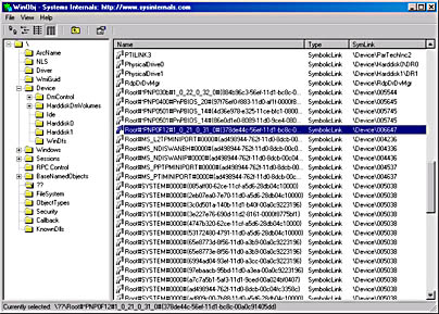
EXPERIMENT
Looking at the \Device DirectoryYou can use the Winobj tool, included as \Sysint\Winobj.exe on the companion CD, or the !object kernel debugger command to view the device names under \Device in the object manager namespace. The following screen shot shows an I/O manager-assigned symbolic link that points to a device object in \Device with an autogenerated name:
When you run the !object kernel debugger command and specify the \Device directory, you should see output similar to the following:
kd> !object \device Object: 81a8e170 Type: (81ab6120) Directory ObjectHeader: 81a8e158 HandleCount: 0 PointerCount: 198 Directory Object: 81a914d0 Name: Device 9 symbolic links snapped through this directory HashBucket[ 00 ]: 81a6de10 Device 'KsecDD' 819c43f0 Device 'Beep' 81a6d6d0 Device 'Ndis' 81a61030 Device '00000019' 81aa7830 Device '003018' 81aa7a30 Device '002918' HashBucket[ 01 ]: 817c3c70 Device '00000026' 819c3d90 Device 'Netbios' HashBucket[ 02 ]: 818d1850 Device 'KSENUM#00000001' 81966890 Device 'Ip' HashBucket[ 03 ]: 818c5b70 Device 'KSENUM#00000002' 81a31038 Device 'Video0' 81a4fc70 Device 'KeyboardClass0' HashBucket[ 04 ]: 819d4410 Device 'NDProxy' 819c0040 Device 'Video1' HashBucket[ 05 ]: 817e7650 Device 'PcCard0-0' 819c70d0 Device 'Eawdmfd' 81a2aa50 Device '{13199AF4-86FA-48C2-8074-468CA06AFB6C}' 819c0ce0 Device 'Video2' 81a52040 Device 'Serial0' 81a6cbb0 Device 'PointerClass0' 81a215f0 Device '0000000a' HashBucket[ 06 ]: 817cb8c0 Device 'Serial1' 81900570 Device 'DebugMessageDevice' 81a277d0 Device 'USBPDO-0' 81a5e030 Device 'CompositeBattery'
When you execute !object and specify an object manager directory object, the kernel debugger dumps the contents of the directory according to the way the object manager organizes it internally. For fast lookups, a directory stores objects in a hash table based on a hash of the object names, so the output shows the objects stored in each bucket of the directory's hash table.
When a file is opened, the filename includes the name of the device object on which the file resides. For example, the name \Device\Floppy0\Myfile.dat refers to the file Myfile.dat on floppy disk drive A. The substring \Device\Floppy0 is the name of the internal Windows 2000 device object representing that floppy disk drive. When opening Myfile.dat, the I/O manager creates a file object and stores a pointer to the Floppy0 device object in the file object and then returns a file handle to the caller. Thereafter, when the caller uses the file handle, the I/O manager can find the Floppy0 device object directly. Keep in mind that internal Windows 2000 device names can't be used in Win32 applications—instead, the device name must appear in a special directory in the object manager's namespace, \?? (named \DosDevices prior to Windows NT 4). This directory contains symbolic links to the real, internal Windows 2000 device names. Device drivers are responsible for creating links in this directory so that their devices will be accessible to Win32 applications. You can examine or even change these links programmatically with the Win32 QueryDosDevice and DefineDosDevice functions.
EXPERIMENT
Viewing Win32 Device Name to Windows 2000 Device Name MappingsYou can examine the symbolic links that define the Win32 device namespace with the Winobj utility included on the companion CD (\Sysint\Winobj.exe). Run Winobj, and click on the \?? directory, as shown here:
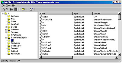
Notice the symbolic links on the right. Try double-clicking on the device C:. You should see something like this:
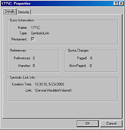
C: is a symbolic link to the internal device named \Device\HarddiskVolume1, or the first volume on the first hard drive in the system. The COM1 entry in Winobj is a symbolic link to \Device\Serial0, and so forth. Try creating your own links with the subst command at a command prompt.
As Figure 9-10 illustrates, a device object points back to its driver object, which is how the I/O manager knows which driver routine to call when it receives an I/O request. It uses the device object to find the driver object representing the driver that services the device. It then indexes into the driver object by using the function code supplied in the original request; each function code corresponds to a driver entry point. (The function codes shown in Figure 9-10 are described in the section "IRP Stack Locations" later in this chapter.)
A driver object often has multiple device objects associated with it. The list of device objects represents the physical and logical devices that the driver controls. For example, each partition of a hard disk has a separate device object that contains partition-specific information. However, the same hard disk driver is used to access all partitions. When a driver is unloaded from the system, the I/O manager uses the queue of device objects to determine which devices will be affected by the removal of the driver.
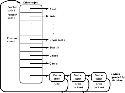
Figure 9-10 The driver object
Using objects to record information about drivers means that the I/O manager doesn't need to know details about individual drivers. The I/O manager merely follows a pointer to locate a driver, thereby providing a layer of portability and allowing new drivers to be loaded easily. Representing devices and drivers with different objects also makes it easy for the I/O system to assign drivers to control additional or different devices if the system configuration changes.
I/O Request Packets
The I/O request packet (IRP) is where the I/O system stores information it needs to process an I/O request. When a thread calls an I/O service, the I/O manager constructs an IRP to represent the operation as it progresses through the I/O system. If possible, the I/O manager allocates IRPs from one of two per-processor IRP nonpaged look-aside lists: the small-IRP look-aside list stores IRPs with one stack location (IRP stack locations are described shortly), and the large-IRP look-aside list contains IRPs with eight stack locations. If an IRP requires more than eight stack locations, the I/O manager allocates IRPs from nonpaged pool. After allocating and initializing an IRP, the I/O manager stores a pointer to the caller's file object in the IRP.
EXPERIMENT
Displaying Driver and Device ObjectsYou can display driver and device objects with the kernel debugger !drvobj and !devobj commands, respectively. In the following example, the driver object for the keyboard class driver is examined, and its lone device object viewed.
Notice that the !devobj command also shows you the addresses and names of any device objects that the object you're viewing is layered over (the AttachedTo line) as well as the device objects layered on top of the object specified (the AttachedDevice line).
Figure 9-11 shows an example I/O request that demonstrates the relationship between an IRP and the file, device, and driver objects described in the preceding sections. Although this example shows an I/O request to a single-layered device driver, most I/O operations aren't this direct; they involve one or more layered drivers. (This case will be shown later in this section.)
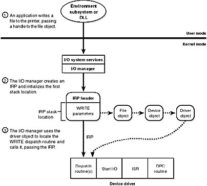
Figure 9-11 Data structures involved in a single-layered driver I/O request
IRP Stack Locations
An IRP consists of two parts: a fixed header (often referred to as the IRP's body) and one or more stack locations. The fixed portion contains information such as the type and size of the request, whether the request is synchronous or asynchronous, a pointer to a buffer for buffered I/O, and state information that changes as the request progresses. An IRP stack location contains a function code (consisting of a major code and a minor code), function-specific parameters, and a pointer to the caller's file object. The major function code identifies which of a driver's dispatch routines the I/O manager invokes when passing an IRP to a driver. An optional minor function code sometimes serves as a modifier of the major function code. Power and Plug and Play commands always have minor function codes.
Most drivers specify dispatch routines to handle only a subset of possible major function codes, including create (open), read, write, device I/O control, power, Plug and Play, System (for WMI commands), and close. (See the following experiment for a complete listing of major function codes.) File system drivers are an example of a driver type that often fills in most or all of its dispatch entry points with functions. The I/O manager sets any dispatch entry points that a driver doesn't fill to point to its own IopInvalidDeviceRequest, which returns an error code to the caller indicating that the function specified for the device is invalid.
EXPERIMENT
Looking at Driver Dispatch RoutinesYou can obtain a listing of the functions a driver has defined for its dispatch routines by entering a 2 after the driver object's name (or address) in the !drvobj kernel debugger command:
While active, each IRP is usually stored in an IRP list associated with the thread that requested the I/O. This arrangement allows the I/O system to find and cancel any outstanding IRPs if a thread terminates or is terminated with outstanding I/O requests.
IRP Buffer Management
When an application or a device driver indirectly creates an IRP by using the NtReadFile, NtWriteFile, or NtDeviceIoControlFile system services (the Win32 API functions corresponding to these services are ReadFile, WriteFile, and DeviceIoControl), the I/O manager determines whether it needs to participate in the management of the caller's input or output buffers. The I/O manager performs three types of buffer management:
- Buffered I/O The I/O manager allocates a buffer in nonpaged pool of equal size to the caller's buffer. For write operations, the I/O manager copies the caller's buffer data into the allocated buffer when creating the IRP. For read operations, the I/O manager copies data from the allocated buffer to the user's buffer when the IRP completes and then frees the allocated buffer.
- Direct I/O When the I/O manager creates the IRP, it locks the user's buffer into memory (makes it nonpaged). When the I/O manager has finished using the IRP, it unlocks the buffer. The I/O manager stores a description of the memory in the form of a memory descriptor list (MDL). An MDL specifies the physical memory occupied by a buffer. (See the Windows 2000 DDK for more information on MDLs.) Devices that perform directory memory access (DMA) require only physical descriptions of buffers, so an MDL is sufficient for the operation of such devices. (Devices that support DMA transfer data directly between the device and the computer's memory, without using the CPU.) If a driver must access the contents of a buffer, however, it can map the buffer into the system's address space.
- Neither I/O The I/O manager doesn't perform any buffer management. Instead, buffer management is left to the discretion of the device driver, which can choose to manually perform the steps the I/O manager performs with the other buffer management types.
For each type of buffer management, the I/O manager places applicable references in the IRP to the locations of the input and output buffers. The type of buffer management the I/O manager performs depends on the type of buffer management a driver requests for each type of operation. A driver registers the type of buffer management it desires for read and write operations in the device object that represents the device. Device I/O control operations (those performed by NtDeviceIoControlFile) are specified with driver-defined I/O control codes, and a control code includes a description of the buffer management the I/O manager should use when issuing IRPs that contain that code.
Drivers commonly use buffered I/O when callers transfer requests smaller than one page (4 KB) and use direct I/O for larger requests. A page is approximately the buffer size at which the trade-off between the copy operation of buffered I/O matches the overhead of the memory lock performed by direct I/O. File system drivers commonly use neither I/O because no buffer management overhead is incurred when data can be copied from the file system cache into the caller's original buffer. The reason that most drivers don't use neither I/O is that a pointer to a caller's buffer is valid only while a thread of the caller's process is executing. If a driver must transfer data from or to a device in an ISR or a DPC routine, it must ensure that the caller's data is accessible from any process context, which means that the buffer must have a system virtual address.
EXPERIMENT
Examining IRPs and the Thread IRP QueueYou can examine the pending IRPs for a thread with the !thread kernel debugger command. One thread that almost always has a pending IRP is the Win32 environment subsystem's keyboard-input thread. To find this thread, execute the !stacks kernel debugger command and locate the thread in Csrss that is listed as having started in the Win32k RawInputThread function:
Then perform the !thread command on the thread's address (the second column):
The sample output shows that the thread's IRP list contains one pending IRP. If you use the !irp command on this IRP, you're likely to see something like this:
This output shows that the IRP has four stack locations and that the keyboard class driver, which is waiting for keyboard input before it completes the IRP, currently owns it.
Another IRP-related debugger command, !irpfind, lets you see all the pending IRPs on the system:
I/O Completion Ports
Writing a high-performance server application requires implementing an efficient threading model. Having either too few or too many server threads to process client requests can lead to performance problems. For example, if a server creates a single thread to handle all requests, clients can become starved because the server will be tied up processing one request at a time. A single thread could simultaneously process multiple requests, switching from one to another as I/O operations are started, but this architecture introduces significant complexity and can't take advantage of multiprocessor systems. At the other extreme, a server could create a big pool of threads so that virtually every client request is processed by a dedicated thread. This scenario usually leads to thread-thrashing, in which lots of threads wake up, perform some CPU processing, block while waiting for I/O, and then, after request processing is completed, block again waiting for a new request. If nothing else, having too many threads results in excessive context switching, caused by the scheduler having to divide processor time among multiple active threads.
The goal of a server is to incur as few context switches as possible by having its threads avoid unnecessary blocking, while at the same time maximizing parallelism by using multiple threads. The ideal is for there to be a thread actively servicing a client request on every processor and for those threads not to block when they complete a request if additional requests are waiting. For this optimal process to work correctly, however, the application must have a way to activate another thread when a thread processing a client request blocks on I/O (such as when it reads from a file as part of the processing).
The IoCompletion Object
Applications use the IoCompletion executive object, which is exported to Win32 as a completion port, as the focal point for the completion of I/O associated with multiple file handles. Once a file is associated with a completion port, any asynchronous I/O operations that complete on the file result in a completion packet being queued to the completion port. A thread can wait for any outstanding I/Os to complete on multiple files simply by waiting for a completion packet to be queued to the completion port. The Win32 API provides similar functionality with the WaitForMultipleObjects API function, but the advantage that completion ports have is that concurrency, or the number of threads that an application has actively servicing client requests, is controlled with the aid of the system.
When an application creates a completion port, it specifies a concurrency value. This value indicates the maximum number of threads associated with the port that should be running at any given time. As stated earlier, the ideal is to have one thread active at any given time for every processor in the system. Windows 2000 uses the concurrency value associated with a port to control how many threads an application has active. If the number of active threads associated with a port equals the concurrency value, a thread that is waiting on the completion port won't be allowed to run. Instead, it is expected that one of the active threads will finish processing its current request and check to see whether another packet is waiting at the port. If one is, the thread simply grabs the packet and goes off to process it. When this happens, there is no context switch, and the CPUs are utilized nearly to their full capacity.
Using Completion Ports
Figure 9-12 shows a high-level illustration of completion port operation. A completion port is created with a call to the Win32 API function CreateIoCompletionPort. Threads that block on a completion port become associated with the port and are awakened in last in, first out (LIFO) order so that the thread that blocked most recently is the one that is given the next packet. Threads that block for long periods of time can have their stacks swapped out to disk, so if there are more threads associated with a port than there is work to process, the in-memory footprints of threads blocked the longest are minimized.
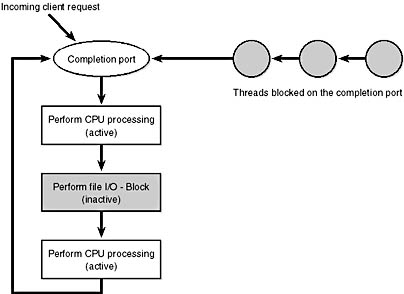
Figure 9-12 I/O completion port operation
A server application will usually receive client requests via network endpoints that are represented as file handles. Examples include Windows Sockets 2 (Winsock2) sockets or named pipes. As the server creates its communications endpoints, it associates them with a completion port and its threads wait for incoming requests by calling GetQueuedCompletionStatus on the port. When a thread is given a packet from the completion port, it will go off and start processing the request, becoming an active thread. A thread will block many times during its processing, such as when it needs to read or write data to a file on disk or when it synchronizes with other threads. Windows 2000 detects this activity and recognizes that the completion port has one less active thread. Therefore, when a thread becomes inactive because it blocks, a thread waiting on the completion port will be awakened if there is a packet in the queue.
Microsoft's guidelines are to set the concurrency value roughly equal to the number of processors in a system. Keep in mind that it's possible for the number of active threads for a completion port to exceed the concurrency limit. Consider a case in which the limit is specified as 1. A client request comes in, and a thread is dispatched to process the request, becoming active. A second request arrives, but a second thread waiting on the port isn't allowed to proceed because the concurrency limit has been reached. Then the first thread blocks waiting for a file I/O, so it becomes inactive. The second thread is then released, and while it's still active, the first thread's file I/O is completed, making it active again. At that point—and until one of the threads blocks—the concurrency value is 2, which is higher than the limit of 1. Most of the time, the active count will remain at or just above the concurrency limit.
The completion port API also makes it possible for a server application to queue privately defined completion packets to a completion port by using the PostQueuedCompletionStatus function. A server typically uses this function to inform its threads of external events, such as the need to shut down gracefully.
EAN: 2147483647
Pages: 121