Chapter 6. WAN Protocols and Technologies: Voice over X
| < Free Open Study > |
Configuring Frame RelayYou need to follow only two physical steps when configuring Frame Relay on Cisco routers. In this text, we list a four-step process; some of these steps do not require configuration. Regardless, you should always be aware of all the components or steps needed to configure the complete frame service. A couple of these commands are set by default, and no additional key-ins are necessary. Further additional steps can be added to the basic steps, but they are not required to get frame service running on your router.
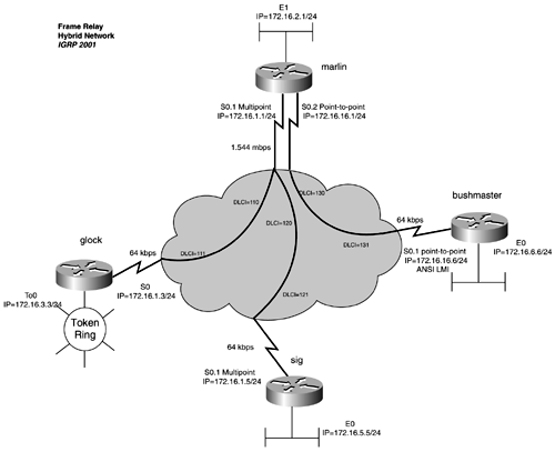
NOTE Split horizon refers to the rule that information about a route will not be sent out the same interface or subinterface from which it was received. Split horizon rears its ugly head most predominantly in multipoint configurations. Here, routing updates flow into one subinterface but also must be sent out that same subinterface to reach the other routers on the multipoint network. Split horizon is on by default and prevents routing updates for EIGRP, IGRP, and RIP from being propagated properly in a multipoint configuration. Disable this with the following interface key-in: no ip split-horizon for RIP or IGRP networks, and no ip split-horizon eigrp autonomous_system for EIGRP networks. These commands have similar forms for IPX and AppleTalk. If you have two point-to-point subinterfaces configured, routing updates flow in one subinterface and are forwarded out the other subinterface because each subinterface is on a different network. Therefore, there is no need to disable split horizon when using point-to-point subinterfaces. Practical Example: Configuring Hybrid Frame Relay NetworksThe example that follows walks you through the complete configuration of a Frame Relay network by using the different types of interfaces. Figure 5-4 illustrates a hybrid Frame Relay network. Figure 5-4. Frame Relay Hybrid Network In this example, you configure a Frame Relay multipoint network between the marlin, glock, and sig routers. You also configure a Frame Relay point-to-point network between the marlin and the bushmaster routers. The routing protocol is IGRP. Let's begin with the marlin router. Following the four-step Frame Relay configuration process, start by setting the encapsulation to Frame Relay on the serial interface. You define two types of subinterfaces. A multipoint is needed for the subnet 172.16.1.0/24, which connects the glock and sig routers. You can use a point-to-point or a multipoint for subnet 172.16.16.0/24 to connect to the bushmaster router. In this example, you use a point-to-point network. Example 5-2 demonstrates this configuration. Example 5-2 Setting Encapsulation and Defining Subinterfacesmarlin# conf t Enter configuration commands, one per line. End with CNTL/Z. marlin(config)# int s0 marlin(config-if)# encapsulation frame-relay marlin(config-if)# int s0.1 multipoint marlin(config-subif)# ip address 172.16.1.1 255.255.255.0 marlin(config-subif)# exit marlin(config)# int s0.2 point-to-point marlin(config-subif)# ip address 172.16.16.1 255.255.255.0 marlin(config-subif)# ^Z You can follow the same steps defining a multipoint subinterface on the glock router and a point-to-point subinterface on the bushmaster router. You will not use any subinterfaces on the glock router, and you should treat it as a multipoint router. At this time, you need only to define the Frame Relay encapsulation on the glock router's s0 interface. The next step is to configure LMI. As previously mentioned, Frame Relay autosense detects and configure the LMI automatically. No additional configuration is needed. For practice, you will statically configure the LMI on the bushmaster router to ANSI. This is accomplished with the frame-relay lmi-type ansi command under the s0 interface. The third step is to configure static or dynamic addressing. On the marlin router, use a static address on the s0.1 interface, the multipoint interface. The s0.2 interface is a point-to-point interface, so you can use dynamic addressing. You need one frame-relay map statement pointing to each remote router on the 172.16.1.0/24 subnet. Example 5-3 demonstrates the configuration for static mapping. Example 5-3 Configuring Static Mappingmarlin(config)# int s0.1 multipoint marlin(config-subif)# frame-relay map ip 172.16.1.3 110 broadcast marlin(config-subif)# frame-relay map ip 172.16.1.5 120 broadcast marlin(config-subif)# exit Example 5-4 demonstrates the configuration of dynamic addressing needed for the marlin router. Example 5-4 Configuring Dynamic Mappingmarlin(config)# int s0.2 point-to-point marlin(config-subif)# frame-relay interface-dlci 130 marlin(config-fr-dlci)# ^Z marlin# The glock router's serial interface is a natural interface on a multipoint network; therefore, you use static addressing. Here, you need two frame-relay map statements. You configure one frame-relay map statement pointing at DLCI 111 for IP address 172.16.1.1, and one pointing at the same DLCI, 111, for IP address 172.16.1.5. Example 5-5 shows the configuration on the glock router serial interface. Example 5-5 Configuring the glock Router's Serial InterfaceInterface serial0 ip address 172.16.1.3 255.255.255.0 no ip directed-broadcast encapsulation frame-relay no ip mroute-cache no fair-queue frame-relay map ip 172.16.1.5 111 broadcast frame-relay map ip 172.16.1.1 111 broadcast The sig router has a multipoint subinterface on s0; therefore, this router also needs two static frame-relay map statements. One frame-relay map statement is for the glock router, and one is for the marlin router. Example 5-6 shows the configuration for the serial interface for the sig router. Example 5-6 sig Router's Serial Interfaceinterface serial0.1 multipoint ip address 172.16.1.5 255.255.255.0 no ip directed-broadcast no ip mroute-cache frame-relay map ip 172.16.1.3 121 broadcast frame-relay map ip 172.16.1.1 121 broadcast ! Returning to the marlin router, you can complete Step 3 for the point-to-point side of the link. The subinterface s0.2 is a point-to-point interface to the bushmaster router. Therefore, you can use dynamic addressing on this interface. To accomplish this, use the f rame-relay interface-dlci dlci_number command under the s0.2 interface, such as in Example 5-7. Example 5-7 Configuring marlin Router's serial 0.2 Subinterfaceinterface serial0.2 point-to-point ip address 172.16.16.1 255.255.255.0 frame-relay interface-dlci 130 ! Repeat this same process for the point-to-point subinterface on the bushmaster router; this time, however, it points toward DLCI 131. Now, you can move on to Step 4 in the configuration process: address any protocol-specific issues. As previously mentioned, a split-horizon issue occurs on a multipoint network running IGRP, such as this one. With the default of split horizon set to on, the marlin router will not forward sig's Ethernet network of 172.16.5.0/24 back out the s0.1 port toward the glock router. It also will not forward the glock router's Token Ring network 172.16.3.0/24 back out its s0.1 port toward the sig router. To resolve this, use the no ip split-horizon command on the marlin router's s0.1 port. You now have full IP connectivity across the Frame Relay network. IGRP uses bandwidth to influence routing decisions. To further tune the network, assign bandwidth statements to all serial interfaces to make routing decisions more accurate. Example 5-8 lists the relevant portions of all the router configurations. Example 5-8 Relevant Configuration Listing for the Routers in Figure 5-4hostname marlin ! interface Ethernet1 ip address 172.16.2.1 255.255.255.0 media-type 10BaseT ! interface Serial0 no ip address encapsulation frame-relay no ip mroute-cache bandwidth 1544 no fair-queue ! interface Serial0.1 multipoint ip address 172.16.1.1 255.255.255.0 no ip split-horizon frame-relay map ip 172.16.1.3 110 broadcast frame-relay map ip 172.16.1.5 120 broadcast ! interface Serial0.2 point-to-point ip address 172.16.16.1 255.255.255.0 frame-relay interface-dlci 130 ! router igrp 2001 network 172.16.0.0 ! ________________________________________________________________ hostname glock ! <<<text omitted>>> ! interface Serial0 bandwidth 64 ip address 172.16.1.3 255.255.255.0 no ip directed-broadcast encapsulation frame-relay no ip mroute-cache no fair-queue frame-relay map ip 172.16.1.5 111 broadcast frame-relay map ip 172.16.1.1 111 broadcast ! interface TokenRing0 ip address 172.16.3.3 255.255.255.0 no ip directed-broadcast ring-speed 16 ! router igrp 2001 network 172.16.0.0 ! ________________________________________________________________ hostname sig ! <<<text omitted>>> ! interface Ethernet0 ip address 172.16.5.5 255.255.255.0 no ip directed-broadcast ! interface Serial0 no ip address no ip directed-broadcast encapsulation frame-relay no ip mroute-cache no fair-queue ! interface Serial0.1 multipoint bandwidth 64 ip address 172.16.1.5 255.255.255.0 no ip directed-broadcast no ip mroute-cache frame-relay map ip 172.16.1.3 121 broadcast frame-relay map ip 172.16.1.1 121 broadcast ! router igrp 2001 network 172.16.0.0 ! ________________________________________________________________ hostname bushmaster ! interface Ethernet0 ip address 172.16.6.6 255.255.255.0 ! interface Serial0 no ip address encapsulation frame-relay frame-relay lmi-type ansi ! interface Serial0.1 point-to-point ip address 172.16.16.6 255.255.255.0 bandwidth 64 frame-relay interface-dlci 131 ! router igrp 2001 network 172.16.0.0 To verify that your Frame Relay network is operational, you can use standard ping s and traces tests; however, sometimes you might want to require more information about the operational status of the Frame network. The "Big show " and "Big D" commands for Frame Relay can provide a lot of useful information, as described in the next section. |
| < Free Open Study > |
EAN: 2147483647
Pages: 283