WORKING WITH 3D OBJECTS
| Illustrator includes a trio of basic but powerful 3D effects. Like any effects, these are live appearance attributes that may be saved in graphic styles. 3D Extrude & BevelInstantly turn any path, shape, or text into a 3D object with the Extrude & Bevel command. This Illustrator effect extrudes, or gives depth to, objects in addition to, or in place of, beveling or chiseling their edges (see Figure 18.10). Figure 18.10. The word Illustrator has been extruded, and CS2 has a bevel.
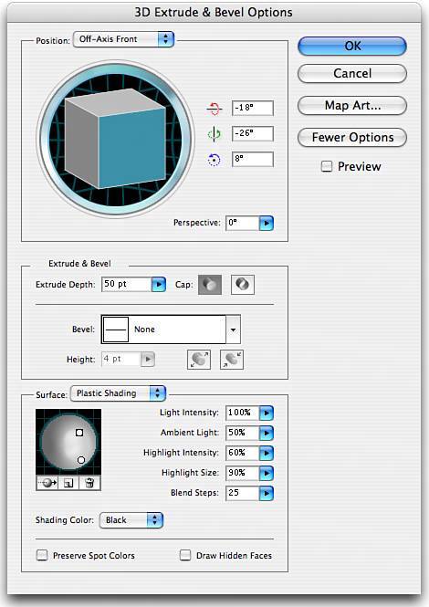
Accessed from the Effect, 3D submenu, the 3D Extrude & Bevel Options command includes everything needed for basic three-dimensional work (see Figure 18.11). In the Position pop-up menu choose a preset position from which to begin the extrusion, or manually set the position by clicking on and dragging the track cube in three dimensional space. The track cube rotates smoothly through all three axes, the rotation of which may also be specified numerically in the x, y, and z axes measurement fields. To create perspective, as if some surfaces of the object are farther away, set Perspective to a degree between 0 and 160. Figure 18.11. The 3D Extrude & Bevel Options dialog (with More Options shown).
In the Extrude & Bevel section set the Extrude Depth, the depth or thickness of the object, and whether the object is solid or hollow (via the two Cap options). To create a chiseled or mitered face, select a Bevel and set its height and whether the bevel is added to the exterior of the object or carved away from the interior. The options in the Surface section define the type of light reflection in four modes (see Figure 18.12):
Figure 18.12. 3D Revolved objects in the four shading modes: Wireframe, No Shading, Diffuse Shading, and Plastic Shading.
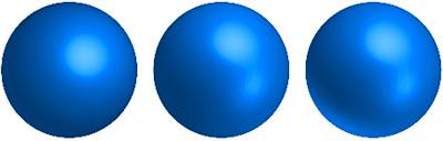
Clicking the More Options button reveals numerous other options in the Surface section. Most prominent is the lighting sphere, which displays at least one light. A light is represented by a white circle on the lighting sphere, and when selected is encased in a box. This is the object's light source(s), from which highlights and shading are calculated (see Figure 18.13). Click and drag on the light to move it around relative to the 3D object. Figure 18.13. Three variations of the same object, with one (left), two (center), and three (right) light sources defined. The third light source was moved to the back to create backlighting.
Beneath the lighting sphere are three buttons:
Add back-lighting to make objects more realistic. Also in the Surface area are several measurement fields and other options that appear depending on the selected shading mode:
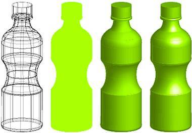
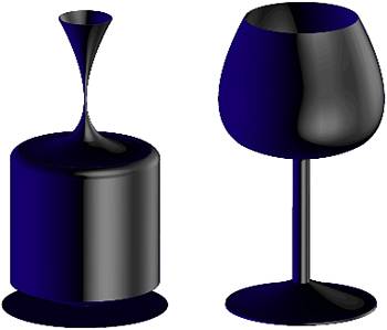
3D Revolve3D Revolve takes an open path and revolves it in three-dimensional space to create a solid object. To create a 3D Revolve object, draw a contour path, an open path forming the shape of the object's side (optionally include path segments to define the radius, or half the diameter, of its top and bottom surfaces) (see Figure 18.14). With the contour path selected, choose Effect, 3D, Revolve. Figure 18.14. The open contour path (left), revolved into a solid 3D object.
In the 3D Revolve Options dialog are Position and Surface sections identical to those in the 3D Extrude & Bevel Options dialog. In place of the Extrude & Bevel section is the Revolve section. Options in the Revolve section are
Try this exercise:
Under some circumstances, white gaps may appear between surfaces or blend steps in 3D objects. These are artifacts, or screen glitches, and neither print nor export. Like the other 3D effects, Revolve is a live effect. Revolved objects are still open paths, and can be edited like any other path, with instantaneous reapplication of the 3D effect. To understand the concept of a live effect, try the following exercise:
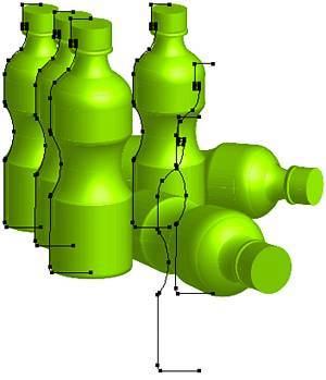
Because the 3D Revolve Options dialog, as well as the other 3D effects dialogs, include full rotation capabilities on all three axes plus perspective, basic transformation of 3D objects' underlying paths is minimized. Though the default revolution is along either the x or y axis (horizontally or vertically), the track cube or axes measurement fields may be employed to rotate an object in any direction (see Figure 18.16). 3D rotation while revolving enables light sources to match across multiple objects when building a scenesomething not possible when the Transform palette accomplishes the transformation. Figure 18.16. All six bottles are exact duplicates of the same path (the rear bottle paths have been scaled down 5%10% for proper perspective). Note that even the overturned bottles' paths (the dark lines) are still vertical, and that, because they were rotated entirely in the 3D Revolve Options dialog, their highlights and shadows fit the scene.
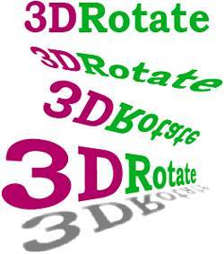
3D RotateRotate is the 3D effect with a unique and simple purpose: to transform objects in three dimensions without making them look like 3D objects (see Figure 18.17). Figure 18.17. Original point type object (top) and three copies, each with different 3D Rotate effect settings. The shadow instance of the 3D rotated text is also feathered with the Effect, Stylize, Feather command, and its blending mode and transparency are adjusted for context.
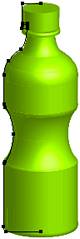
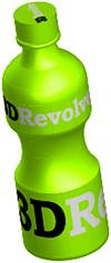
The 3D Rotate Options dialog (accessible by choosing Effect, 3D, Rotate) is, for all intents and purposes, merely the Position section from the 3D Extrude & Bevel options dialog and the 3D Revolve Options dialog. It includes the Position presets, track cube, and measurement fields for the x, y, and z axes as well as Perspective. The Surface area includes a subset of the other 3D tools, with options limited to No Shading and Diffuse Shading. Despite being 3D rotated, the type in these objects is editable at all timesjust like the path in the 3D Revolve section of this chapter. Because 3D objects are effects, their contents always remain editable. Mapping Artwork to 3D ObjectsIn the 3D Extrude & Bevel Options and 3D Revolve Options dialogs is the Map Art button, which enables mapping or painting symbol artwork on to the surfaces of 3D objects (see the section "Understanding Symbols," later in this chapter). Map Art can apply any symbol to any surface of an extruded, beveled, or revolved object (see Figure 18.18). Figure 18.18. The 3D revolved bottle with simple mapped art.
To map art to a 3D object, create symbols from the art to be mapped to each surface. Then create a 3D object, and, in the 3D Extrude & Bevel Options or 3D Revolve Options dialog, click the Map Art button. The Map Art dialog box (see Figure 18.19) shows each of the surfaces created by the 3D effect. With a box, for example, there would be six surfaces for each face of the 3D box. The total number of surfaces, as well as First Surface, Previous Surface, Next Surface, and Last Surface navigation buttons, is at the top of the dialog. In the main window section below it is the surface preview. Light gray areas in the surface preview are surfaces visible in the 3D object as it is currently positioned; dark gray areas are hidden surfaces. As each surface becomes active in the Map Art dialog, that surface in the 3D object is outlined in red in the document window. Figure 18.19. The Map Art dialog box.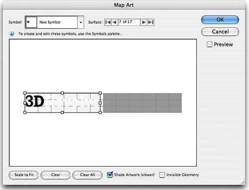 From the Symbol menu choose the artwork to be mapped to the surface. It appears in the surface preview with a bounding box. The bounding box enables resizing and rotating (move the cursor just outside a corner control point) of the artwork. Arrange the artwork to fit within the desired area. Use the surface navigation buttons to cycle through the various surfaces, applying artwork as needed. Each surface may have the same or a different symbol mapped to it. At the bottom of the Map Art dialog box are three buttons and two check boxes:
If the geometry of the 3D object changes, mapped art may alter as well, either to change position or, in the case of adding or subtracting surfaces, to disappear. Because symbols exist outside of 3D objects, and the Map Art dialog only references symbols, making changes to a symbol on the Symbols palette automatically updates the 3D object's mapped art. |
EAN: 2147483647
Pages: 426
- Enterprise Application Integration: New Solutions for a Solved Problem or a Challenging Research Field?
- Context Management of ERP Processes in Virtual Communities
- Distributed Data Warehouse for Geo-spatial Services
- Data Mining for Business Process Reengineering
- A Hybrid Clustering Technique to Improve Patient Data Quality