USING LINE TOOLS
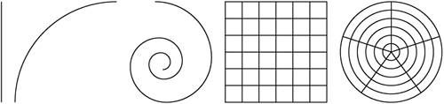
| Adjacent to the shape tools are the Line tools, which create open paths that are either simpler or more complicated than the basic closed shapes discussed in the previous section (see Figure 16.8). They appear on the Tools palette to the left of the shape tools; the Line tool shows by default, with the rest behind it. Click and hold on the Line tool to access the other path tools. Figure 16.8. Illustrator's five default line constructs, from left to right: Line, Arc, Spiral, Rectangular Grid, and Polar Grid.
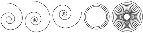
Line Segment ToolWhen a straight line is desired, the Line tool is often the fastest way to create it. Merely click to set the start point and drag until the desired end point is reached. Hold the Shift key while dragging to constrain the line to angles that are increments of 45°:0°, 45°, 90°, 135°, 180°, 225°, 270°, 315°, and 360°. Hold the Alt key (Windows users) or Option key (Mac users) to draw from the center outward, as with the Rectangle, Ellipse, and other tools. Click and release to produce the Line Segment Tool Options, which enable precise length and angle definition. Filling the line has no effect unless the line is incorporated into a larger path, at which point the fill color floods the space between line segments. Arc ToolSimilar to the Line Segment tool, the Arc tool creates curved segments rather than straight segments. Click to initiate the arc and then drag to the desired end point. Hold Shift while dragging to constrain the angle of the end point relative to the start point to 45°, 135°, 225°, or 315°. Hold the Alt key (Windows users) or the Option key (Mac users) while dragging to draw the arc from the center outward. Click and release with the Arc tool to access the Arc Segment Tool Options, where the length of the arc across the x axis (horizontally) and y axis (vertically) may be specified, as well as the Type (open or closed), along which axis the arc is based, the slope of the arc (positive values are convex, negative concave), and whether to fill the arc with the active fill swatch. Spiral ToolSpirals are collections of arcs, with four in each complete wind. The winds decay, or decrease in size, with each revolution. A spiral may have between 2 and 1000 arc segments (see Figure 16.9 for several different spirals). Figure 16.9. Different spirals created with the Spiral tool.
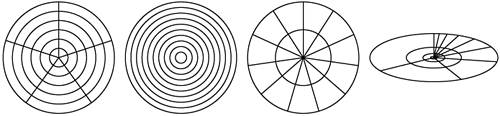
Create spirals by clicking and dragging with the Spiral tool. Click to set the center point and then drag to draw outward from the center and determine the overall size and the space between winds. The rotation of the cursor determines the rotation of the spiral, from center point to end point. Hold Shift while drawing to constrain the angle of rotation to an increment of 45°. While drawing, hold the up or down arrow to increase or decrease the number of winds in the spiral. To increase or decrease the number of winds relative to the size of the spiral, hold the Alt key (Windows users) or the Option key (Mac users) while dragging, which also increases or decreases the spiral's decay rate, or the amount of space between winds. Click and release with the Spiral tool to set Spiral options like the radius, decay percentage, number of segments, and the style. Rectangular Grid ToolCreate rectangular grids to hold tabular data, to use as the basis for meshes and warps, and to aid in perspective drawing by using the Rectangular Grid tool. With the Rectangle Grid tool selected, click and drag until the grid is the desired size. Increase or decrease the number of horizontal lines by pressing the up or down arrow while dragging; use the left and right arrows to control the number of vertical lines while dragging. Adjust the skew of horizontal dividers in 10% increments by pressing V to increase or F to decrease. Use C and X to increase or decrease the skew of vertical dividers while dragging. Click and release to access the Rectangular Grid Tool Options, which enables advanced control over the construction of the grid. Width and Height are the dimensions of the entire griddividers distribute evenly across this areaand the reference point locator determines from which corner the grid is drawn. Specify the number of horizontal and vertical dividers and their skew. Checking Use Outside Rectangle as Frame creates a rectangle path instead of using strokes for the top, right, bottom, and left borders. Fill Grid fills the grid with the currently selected fill color. To deconstruct the grid into a rectanglethe fill and/or frameand horizontal and vertical rules, select Object, Ungroup. Polar Grid ToolLine constructs such as concentric circles and lines radiating around a circleused to create tick marks on a clock, for exampleare easy to create with the Polar Grid tool (see Figure 16.10). Figure 16.10. Different constructs created with the Polar Grid tool.
Click and drag with the Polar Grid tool to create the default polar grid, drawing from the upper-left corner. Hold the Alt key (Windows users) or the Option key (Mac users) while dragging to draw from the center outward. The grid will be sloped or oval-shaped very much like drawing with the Ellipse tool. Hold Shift while drawing to constrain the polar grid to a circle. Increase or decrease the number of radial dividers (the lines emanating from the center point) by pressing the left or right arrow while dragging; use the up or down arrow to control the number of concentric (circle) dividers while dragging. Adjust the skew of radial dividers in 10% increments by pressing V to increase or F to decrease. Press C or X to increase or decrease the skew of concentric dividers while dragging. Click and release with the Polar Grid tool to access the Polar Grid Tool Options dialog. Set the overall width and height, the number and skew of concentric and radial dividers, whether to create a compound path from the ellipses of the concentric dividers, and whether to fill the polar grid with the currently selected fill color. |
EAN: 2147483647
Pages: 426