Handling Advanced Protocols
|
One of the most important features of all firewalls is their ability to intelligently handle many different protocols and applications. If all our needs were satisfied by devices that simply allow, say, outgoing connections to port 80 (HTTP) and deny incoming connections to port 139 (NetBIOS), the life of a security engineer would be much simpler. Unfortunately, many applications, some of which were developed even before the idea of a firewall emerged, act in a much more complicated manner than Telnet or HTTP. One of earliest examples is File Transfer Protocol, or FTP (which we discuss in detail in the next section). The general problem these applications pose is that they use more than one connection to operate and only one of these connections occurs on a well-known port, while the others use dynamically assigned port numbers, which are negotiated in the process of communication. Figure 10.1 shows an example of what happens when this situation occurs and no special measures are in place. (This is a simplified example of SQL*net session negotiation.)
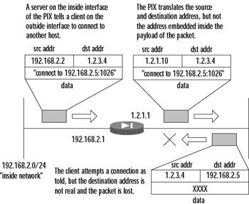
Figure 10.1: Client Redirection without Application Inspection
Thus, any firewall that wants to handle these negotiations well needs the ability to monitor them, understand them, and adjust its rules accordingly. This situation becomes even more complicated when NAT or PAT are involved; the firewall might need to change the data portion of a packet that carries embedded address information in order for the packet to be correctly processed by a client or server on the other side of PIX. There are many implementations of this feature for various firewalls—for example, Stateful Inspection in the Check Point product family or the Adaptive Security Algorithm (ASA) of Cisco PIX devices.
The ASA uses several sources of information during its operation:
-
Access control lists (ACLs), which allow or deny traffic based on hosts, networks, and the TCP or UDP ports involved.
-
Internal translation (xlate) and connection (xlate) tables, which store information about the state of the established connections and are used for fast processing of the traffic that belongs to these connections.
-
Embedded rules for application inspection, which allow automatic processing of most of the complicated cases mentioned. Although some of these rules are configurable, others are fixed.
Here we look at the processing of a TCP packet by ASA, including application-level intelligence (not considering address translation):
-
If the packet is not the first one in a connection (with the SYN bit set), it is checked against internal tables to decide if it is a reply to an established connection. If it is not, the packet is denied.
-
If it is a SYN packet, it is checked against internal tables to decide if it is a part of another established connection. If it is, the packet is permitted and internal tables are adjusted in order to permit return traffic for this connection.
-
If this SYN packet is not a part of any established communication, it is checked against ACLs.
-
If the SYN packet is permitted, the PIX creates a new entry in internal tables (the XLAT and/or CONN table).
-
The firewall checks to see whether the packet needs additional processing by application-level inspection algorithms. During this phase, the firewall can create additional entries in internal tables. For example, it can open a temporary conduit for an incoming FTP connection based on the PORT command that it sees in the packet. "Temporary" means that this conduit will exist only until the FTP session terminates and will be deleted after the session is closed.
-
The inspected packet is forwarded to the destination.
The situation for UDP is similar, although simpler because there are no distinct initial packets in the UDP protocol, so the inspection simply goes through internal tables and ACLs and then through application inspection for each packet received. Figure 10.2 illustrates how the same example from Figure 10.1 would work with application inspection turned on.
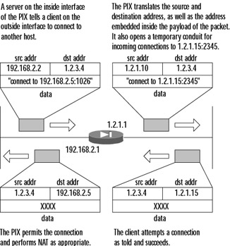
Figure 10.2: Application Inspection in Action
The PIX uses source/destination port numbers to decide if application inspection is needed for a particular packet. Some of these ports are configurable and others are not. Table 10.1 summarizes the application inspection functions provided by PIX firewall software v6.2.
| Application | PAT Support | NAT 1-1 Support | Configurable? | Default Port | Related Standards |
|---|---|---|---|---|---|
| H.323 | Yes | Yes | Yes | UDP/1718 | H.323, H.245, |
| H.323 RAS | Yes | Yes | Yes | UDP/1719 | N/A |
| SIP | Yes | Yes | Yes | UDP/5060 | RFC2543 |
| FTP | Yes | Yes | Yes | TCP/21 | RFC1123 |
| LDAP (ILS) | Yes | No outside NAT | Yes | TCP/389 | N/A |
| SMTP | Yes | Yes | Yes | TCP/25 | RFC821, 1123 |
| SQL*Net v.1, v.2 | Yes | Yes | Yes | TCP/1521 (v.1) | N/A |
| HTTP | Yes | Yes | Yes | TCP/80 | RFC2616 |
| RSH | Yes | Yes | Yes | TCP/514 | Berkeley UNIX |
| SCCP | No | Yes | Yes | TCP/2000 | N/A |
| DNS | Yes | Yes | No | UDP/53 | RFC1123 |
| NetBIOS over IP | See next two entries | ||||
| NBNS/UDP | No | No | No | UDP/137 | N/A |
| NBDS/UDP | Yes | Yes | No | UDP/138 | N/A |
| Sun RPC | No | No | No | UDP/111 | N/A |
| XDCMP | No | No | No | UDP/117 | N/A |
| RTSP | No | No | Yes | TCP/554 | RFC2326, |
| CU-SeeMe | No | No | No | UDP/7648 | N/A |
| ICMP | Yes | Yes | No | N/A | N/A |
| VDO Live | No | Yes | No | TCP/7000 | N/A |
| Windows Media (NetShow) | No | Yes | No | TCP/1755 | N/A |
The main command that is used to configure the services stated as "configurable" in Table 10.1 (FTP, H.323, HTTP, ILS, RSH, RTSP, SIP, SSCP, SMTP, and SQL*Net) is the fixup command. Its basic syntax is:
[no] fixup protocol [protocol] [port]
The following sections describe how this command is used for each protocol. Depending on the protocol it is used with, application inspection (fixup) provides the following functionality for complex protocols:
-
Securely and dynamically open and close temporary conduits for legitimate traffic
-
Network Address Translation
-
Port Address Translation
-
Inspect traffic for malicious behavior
File Transfer Protocol
One of the first application-level protocols that posed problems for simple packet-filtering devices was FTP, which is documented in RFC959. FTP always uses two connections for operation. The first one, known as the control connection, is a connection from the client FTP program to the server's FTP port (TCP port 21 by default). This connection is used for sending commands to the server and receiving informational replies. These commands and replies are a little different from what you enter on the keyboard. For example, when you log in to an FTP server and enter your username, your FTP client sends the USER username command to the server and probably receives a reply 331 User name okay, need password. It then asks you for your password, and the login process completes.
The second connection is opened for the actual file transfer operation and can behave differently depending on the mode in which the client is operating; it can be initiated either by the client or by the server. The main difference is whether the client tells the server to operate in passive or active mode.
Active vs. Passive Mode
The first FTP servers and clients used active mode, where a file transfer happens as shown in Figure 10.3 and described here:
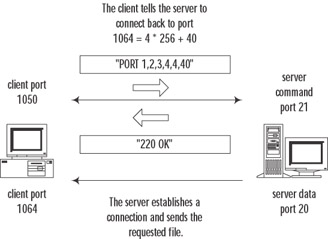
Figure 10.3: Active FTP Connection Flow
-
When the client (already connected to the server's FTP control port and logged in) needs to receive a file from the server, it sends a PORT A1,A2,A3,A4,a1,a2 command, where A1, A2, A3, and A4 are the four octets of the client's IP address, and a1 and a2 are the port numbers on which it will listen for connections. This port number is an arbitrary value and is calculated as a1*256+a2.
-
After receiving a 200 OK reply from the server, the client sends the RETR command to start the transfer.
-
The server opens a connection to the port that the client specified and pipes the file's contents into this connection. After the file is transferred, this data connection is closed, while the control connection stays open until the client disconnects from the server. The source port of this connection is "ftp-data," TCP port 20.
Now, if the client is behind a firewall (or, in PIX terms, is on a higher security-level interface than the server), the connection from the server is likely to be refused unless the firewall permits inbound connections to all high ports on the client side, which is of course not good. The PIX firewall can monitor FTP control connections, so when it discovers a PORT command issued by the client, it temporarily permits inbound connections to the port requested by the client in this command.
The other issue here is that when NAT or PAT are used, the PIX also translates the address and port number (A1.A2.A3.A4:a1a2) inside this command to the NATed IP and port. For example, if the client's address is 10.0.0.1 and it is translated to 1.2.3.4, the PORT 10,0,0,1,4,10 command the client issued (which says that the client is ready to receive connections to 10.0.0.1:1034) during its transit through the PIX will be translated to something like PORT 1,2,3,4,8,10, so that the server will open the data connection to 1.2.3.4:2058. This destination will be properly translated by the PIX to 10.0.0.1:1034 using its internal tables.
The second mode of FTP operation is passive mode. In this mode, a file transfer happens as shown in Figure 10.4 and described here:
-
Soon after connecting to the server's FTP control port and logging in, the client sends the PASV command, requesting the server to enter the passive mode of operation.
-
The server responds with "227 Entering Passive Mode A1,A2,A3,A4,a1,a2." This response means that the server is now listening for data connections on the IP address and port it has specified in the reply.
-
The client connects to the specified port and sends the RETR command to start the transfer.
-
The server sends the file's contents over this second (data) connection.
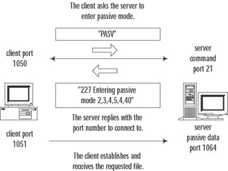
Figure 10.4: Passive FTP Connection Flow
This mode of operation does not cause a problem when the client is on a more secure interface, since by default the client is permitted to initiate any outbound connections. Unfortunately, there is a problem when the server is on a more secure interface than the client; the firewall will generally not allow the client to open an inbound connection on an arbitrary port. To overcome this problem, the PIX firewall monitors PASV commands and "227" replies, temporarily permits an inbound connection to the specified port, and modifies IP addresses and port numbers to correspond with NATed ones.
The described behavior of the PIX firewall is turned on by default; it inspects inbound and outbound connections to FTP control port 21. To turn it off or modify the port numbers on which it should perform inspection, use the fixup protocol ftp command in configuration mode. The syntax of this command is as follows:
[no] fixup protocol ftp [strict] [<port>]
Here, port is the port number used for control connections, PORT commands, and "227" replies. The default state of FTP inspection is equal to:
fixup protocol ftp 21
If you enter extra fixup commands, the ports specified in them are inspected simultaneously for incoming and outgoing FTP control connections. For example, if you enter fixup protocol ftp 2100, both default the default port (21) as well as port 2100 will be inspected. The command no fixup protocol ftp [port] disables the previously entered fixup command. For example, to enable processing of only connections to port 2100, you need to configure the following:
PIX1(config)# fixup protocol ftp 2100 PIX1(config)# no fixup protocol ftp 21
It is possible to disable inspection of FTP connections using no fixup protocol ftp. The result will be that inside users are able to initiate FTP connections to outside hosts only in passive mode, not active mode. Outside clients will be able to initiate FTP connections to inside servers in active mode only (assuming there is a static NAT entry and an access list or conduit in place), not passive mode. To reset application inspection to the standard port settings for all protocols at the same time, use the clear fixup command.
The full functionality of FTP application inspection consists of the following tasks:
-
Tracking of FTP command and response sequence (PORT and PASV commands and "227" replies).
-
Creating a temporary conduit for the data connections based on the result of this tracking (if necessary).
-
NATing of IP addresses inside the commands and replies.
-
Generating an audit trail.
An audit trail is generated in the following cases:
-
An audit record 302002 is generated for each uploaded or downloaded file.
-
Each download (RETR) or upload (STOR) command is logged.
-
File operations are logged together with the FTP username, source and destination IP addresses, and NAT address.
-
An audit record 201005 is generated if the firewall failed to allocate a secondary channel due to memory shortage.
In the first implementations of FTP inspection, the process of looking for the relevant commands/replies in IP packets was very simple: The PIX only looked for a string such as PORT inside the packet and tried to interpret it as a corresponding command. Of course, various attacks were designed to fool the firewall into opening an extra port by sending bogus commands and replies from the client or the server (see www.cisco.com/warp/public/707/pixftp-pub.shtml).
Since then, the inspection process has been greatly improved, and another option, strict, has been introduced to perform much more rigorous checks on the command/response stream. If you use this option in configuration of FTP inspection—for example, fixup protocol ftp strict 21—the firewall imposes much more rigorous restrictions on the command/response flow. These restrictions can sometimes break applications that are not fully RFC compliant. If one of the following problems is encountered, the connection is denied or dropped:
-
Clients are prevented from sending embedded commands. The connection that tries to use these commands is closed. This action is performed by checking how many characters are present in the PORT or PASV command after the IP address and port number. If there are more than eight characters, it is assumed that it is an attempt to add another command at the end of the line, and the connection is dropped.
-
Before a new command is allowed, the server should send a reply to each command received.
-
Only servers can generate "227" messages (protection against reply spoofing), and only clients can generate PASV and PORT commands (protection against command spoofing). The reason here is that without strict, a client can send any garbage to the server, including fake "227" messages—for example, 227 foobar A1, A2, A3, A4, a1, a2, and although the server replies with an error message, the firewall could be fooled into permitting the connection with the parameters specified.
-
Extra checking of "227" and PORT commands is performed to ensure that they are really commands/replies, not a part of some error message.
-
Truncated commands; PORT and PASV commands are checked for the correct number of commas in them. Each should contain only five commas (see previous examples).
-
Size of RETR and STORE commands; their length (including the filename for download/upload) should not be greater than an embedded constant. This is done to provide protection against possible buffer overflows.
-
Invalid port negotiation; the port number used for the data connection must be a high port (that is, a port with number greater than 1024).
-
Every FTP command sent by the client must end with <cr><lf> characters, as specified by RFC959.
Domain Name Service
The main task of application inspection for DNS (known as DNS Guard) is to impose specific restrictions on DNS requests over UDP that pass through the firewall (compared with the generic processing of all UDP communications). Roughly speaking, the data part of each DNS request contains a serial number (ID) and the body of the request. For example, requests for "A-records" (address records) include the DNS name for which an IP address is sought. The reply to this request should contain the same ID and an IP address.
DNS Guard ensures the following:
-
Only replies with the correct ID are accepted.
-
Only one reply is accepted. In the case of multiple replies, all but the first one are ignored.
-
The UDP connection associated with the DNS connection is destroyed as soon as a DNS reply is received, not after the UDP timeout has expired.
-
IP addresses in A-record replies are translated if necessary. This process is controlled by the alias command. It also translates addresses to be consistent with NAT statements, including outside NAT, which was introduced in v6.2. Generally, the alias command is not needed because of this outside NAT feature.
As an example for the last case, consider the configuration in which a client (192.168.0.1) and a Web server (web.company.com, IP address 192.168.0.5) are located on the inside interface of PIX and have nonroutable addresses. A DNS server is on the outside. The PIX is configured to translate both the client and the server addresses via PAT to a single IP of 1.2.3.4. This address is recorded on the DNS server as an address for web.company.com. When a client requests an IP address (an A-record) for the server, the PIX forwards the request to the DNS server, translating the source IP. When it receives the DNS server's reply, it not only translates the packet's destination IP address (changing 1.2.3.4 to 192.168.0.1), but it also changes the address of the Web server contained in the reply's data field (that is, 1.2.3.4 contained in the reply is changed to 192.168.0.5). As a result, the internal client will use the internal address 192.168.0.5 of the Web server to directly connect to it. Figure 10.5 illustrates how the DNS request and reply pass through the PIX.
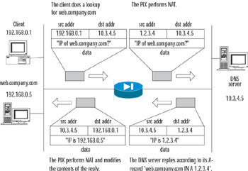
Figure 10.5: The DNS Guard Operation
When the DNS server is on a more secure interface than the Web server and/or client, either outside NAT (preferred in v6.2) or alias commands are used. Outside NAT is very similar to the previous situation. Before v6.2, you needed to use the alias command alias internal_server_address external_server_address in order to process A-record replies properly in this case.
| Note | When using alias commands for DNS fixups, you need to turn off proxy ARP on the internal interface, using the sysopt noproxyarp inside_interface command. It is also possible to turn off processing of DNS replies for addresses stated in the alias commands by using the sysopt nodnsalias command. |
It is not possible to disable application inspection of DNS or change the DNS port from the default of 53.
Simple Mail Transfer Protocol
Similar to FTP and DNS inspection, application inspection of Simple Mail Transfer Protocol (SMTP), also known as Mail Guard, is designed to restrict what servers and clients can do and see while not harming the essential functionality of the protocol—sending electronic mail.
SMTP is described in RFC821 as a Telnet-based protocol designed for transferring electronic mail between servers. The client sends commands to the server, and the server replies with status messages and probably some extra information. In essence, it is very simple: There are commands for specifying a recipient of the message, the sender, and the message itself. An example of an SMTP session is shown in the following output.
Server: 220 Simple Mail Transfer Service Ready Client: HELO example1.com Server: 250 OK Client: MAIL FROM:<Alice@example1.com> Server: 250 OK Client: RCPT TO:<Bob@example2.com> Server: 250 OK Client: RCPT TO:<John@example2.com> Server: 550 No such user here Client: DATA Server: 354 Start mail input; end with <CRLF>.<CRLF> Client: Blah blah blah... Client: ...foobar. Client: <CRLF>.<CRLF> Server: 250 OK Client: QUIT Server: 250 OK
This transcript shows the session in which the client tried to send e-mail from Alice@example1.com to Bob@example2.com, which was accepted, and to John@example2.com, which was rejected because a user was not found.
These commands (HELO MAIL, RCPT, DATA, and QUIT), together with a couple of control commands (NOOP, do nothing, and RSET, reset state) make up a minimal set required by RFC821, section 4.5.1.
Mail Guard is turned on by default on port 25 and can be reconfigured using the following command:
[no] fixup protocol smtp [<port>[-<port>]]
This command functions in the same way as fixup protocol ftp, except that it is possible to specify a range of TCP ports instead of only one.
The main goal of Mail Guard is to restrict commands clients use to the minimal set described, while monitoring the entire command/response sequence and generating a specific audit trail. In detail:
-
Mail Guard monitors commands sent by a client, and if a command does not belong to the minimal set, it is replaced with the NOOP command.
-
If Mail Guard encounters an unknown command, the whole data portion of a TCP/IP packet is filled with the X symbol, which, when received by a server, causes the server to produce an error.
-
MAIL and RCPT commands are monitored for correct usage of <, >, and | characters. The pipeline character | is replaced with a space, and < and > are allowed only when they appear as delimiters of an e-mail address. When an invalid character is replaced in the e-mail address, audit record 108002 is generated.
-
Mail Guard checks for truncated or incorrectly terminated commands (ones that do not end with <cr><lf>).
-
In a banner message—for example, "220 foobar email server ready"—all symbols except "220" are changed to X. This is done in order to hide details about the server platform or operating system, which are often reported in these banners.
| Warning | When enforcing a minimal command set, the PIX causes some problems with Microsoft Exchange servers and Outlook clients. The problem here is that Microsoft's implementation of SMTP is not strictly RFC821 compliant and uses the EHLO command instead of HELO to start a connection. The PIX changes this command to NOOP, so the server simply returns a "250 OK" reply, which is interpreted as a confirmation that the server supports SMTP extensions. Consequently, clients do not fall back to the HELO command and continue using extended features (see RFC2821), which are blocked by the PIX. Most non-Microsoft clients, though, after receiving a simple "250 OK" reply instead of a more informative EHLO response, do fall back to the HELO style of operations and everything works well. |
Hypertext Transfer Protocol
With HTTP application inspection active, all traffic to and from the specified ports is subject to the following:
-
Logging of all HTTP GET requests
-
Screening of URLs by either a Websense or an N2H2 server
-
Filtering of ActiveX and Java content
The command for using application inspection for HTTP is shown here:
[no] fixup protocol http [<port>[-<port>]]
As with SMTP, it is possible to state a range of ports. The default port is 80. URL screening and active content filtering are described later in the chapter, in the "Filtering Web Traffic" section, and is configured using the filter command. Note that when you turn HTTP inspection off using no fixup protocol http, all HTTP inspection is disabled, even if URL screening rules are configured.
Remote Shell
The r-utilities (rsh, rcp, rexec, and rlogin) were developed to be convenient tools for remote command executions on UNIX machines, without the need for logging in as in Telnet. These utilities are inherently very insecure and are being phased out everywhere and replaced by SSH-based tools. Most applications that still use these utilities can be changed to use SSH-based means of authentication and file transfer.
Having said that, let's consider how this protocol works and why it poses problems for firewalls. When you try to connect to a remote host via Remote Shell (rsh), the following happens:
-
The rshd server on the remote host listens on a specified port (TCP port 514, by default) for incoming connections. The client establishes a connection to this port.
-
Immediately after the connection is established, the client sends an ASCII-coded number to the server. This is the port number that the server should use for establishing a secondary connection back to the client. This secondary connection is established so that the server can send any error output to the client. (More precisely, the server will pipe a stderr stream to this secondary connection.) This port number is not fixed, so if the firewall does not allow arbitrary connections to the client—for example, when the client is on a more secure interface)—this secondary connection from the server to the client will fail. In this case, the server closes the first connection and generates an error message, "Can't make pipe." See Figure 10.6 for an example of connection flow.
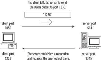
Figure 10.6: RSH Connection Establishment -
After an inbound connection to the client is established, the server performs client authentication. The client sends the server a command to be run on the server and receives the results of its execution (stdout stream) on the first connection, plus any errors that occurred on the second connection.
-
Both connections are closed.
In order to process outbound rsh connections, the PIX monitors the initial connection, notes the port number the client requested, and opens a temporary conduit for the incoming connection by the server. The PIX is also able to perform PAT for this port if it is needed. The command to enable or disable application inspection for rsh is:
[no] fixup protocol rsh <port>
Inbound rsh connections do no need any special processing, only an access-list entry or conduit for an outside client to reach port 514 (default port for rsh) on the inside server.
| Note | The r-utilities are inherently very insecure. Please consider using SSH instead. |
Remote Procedure Call
Remote procedure call (RPC) is a very general mechanism for client-server applications developed by Sun Microsystems. Many applications are built on top of this system, the most important of which are Network File System (NFS) and Network Information System (NIS), which are used in many UNIX networks.
The RPC server is a collection of procedures, each of which can be called by a client sending an RPC request to the server, possibly passing some parameters. The server runs the required procedure and sends the results to the client. This data exchange is platform-independent and is encoded using External Data Representation (XDR) format. Each procedure is identified by an assigned program number, which the client indicates in the request. The default correspondence between program numbers and procedures is stored on UNIX hosts in the /etc/rpc file. To further complicate things, an RPC server can run various versions of each program at the same time. In this case, the version numbers are added to the request.
On TCP/IP networks, each version of a program running on the server is assigned a TCP and a UDP port (both ports have the same number). In order for this service to be generic (and because RPC programs do not use reserved port numbers), there is no fixed correspondence between program names (or numbers) and the ports they are running on. The ports are assigned dynamically by a separate daemon called portmapper, which functions as a multiplexing service. Each program has to register with portmapper in order to be available for RPC calls. Portmapper then reserves a TCP and a UDP port for it. When a client wants to make a call to a remote procedure, it first queries the portmapper daemon (which runs on port 111 by default), sending it a program number and receiving the number of a port it runs on. The client then connects to this port and interacts directly with the required program. Figure 10.7 illustrates this process.
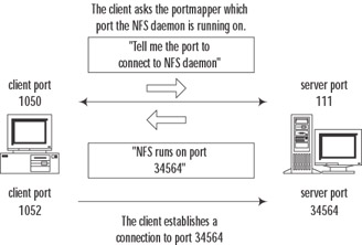
Figure 10.7: RPC Connection Flow
Here, the problem for a firewall arises when the RPC server is on a more secure interface; it is simple to set up a conduit permitting incoming connections to the portmapper port 111, but it is not possible to know beforehand which extra ports need to be opened for incoming RPC requests to specific programs. The PIX does the following:
-
It inspects all outgoing packets that have a source port of 111.
-
When it notices a portmapper reply with some port number, the PIX opens embryonic TCP and UDP connections on this port.
-
The PIX does not inspect RPC packets for anything else. For example, it does not attempt to translate embedded IP addresses.
This feature is not configurable.
Real-Time Streaming Protocol, NetShow, and VDO Live
In this section, we examine streaming applications and the problems they pose to firewalls. Streaming is a form of communication in which the client requests that the server send data at a certain speed. In some implementations, the client needs to confirm each portion of data received. In others, the server just sends data until the client tells it to stop. Major protocols widely used in this area are Real-Time Streaming Protocol, or RTSP (used by RealPlayer, Cisco IP/TV, and Apple QuickTime 4), NetShow (used by Microsoft Media Player), and VDO Live.
The RTSP, defined in RFC2326, is used for session setup and teardown as well as for controlling data flow (stop, play, pause). The RFC allows RTSP to run over both TCP and UDP, but all commercial implementations use only TCP, so Cisco supports application inspection for TCP-based RTSP sessions only. RTSP is a text-based, HTTP-like protocol by which the client sends requests and obtains replies from the server. Requests may be used to negotiate the transport that will be used for streaming data transmission, the options that are supported, asking the server to start or stop streaming, and the like. Embedded in RTSP is Session Description Protocol (SDP, described in RFC2327), which is used to provide the client with some extra information about the source of a datastream, including its physical location (in terms of IP addresses). The following is an example of an RTSP/SDP session (with nonrelevant parts skipped):
C> OPTIONS rtsp://www.play.com:554 RTSP/1.0 C> CSeq: 1 S> RTSP/1.0 200 OK S> CSeq: 1 S> Server: RealMedia Server Version 6.0.3.354 (win32 S> Public: OPTIONS, DESCRIBE, ANNOUNCE, SETUP, GET_PARAMETER, SET_PARAMETER, TEARDOWN S> RealChallenge1: 15d67d72b49fd4895774cfbb585af460 <skipped> C> SETUP rtsp://www.play.com:554/g2audio.rm/streamid=0 RTSP/1.0 C> CSeq: 3 C> RealChallenge2: 319cd1020892093a7b7290ef22b6f41101d0a8e3, sd=3d00792f C> Transport: x-real-rdt/mcast;client_port=6970;mode=play,x-real- dt/udp;client_port=6970;mode=play,x-pn-tng/udp;client_port=6970; mode=play,rtp/avp;unicast;client_port=6970-6971; mode=play S> RTSP/1.0 200 OK S> CSeq: 3 S> Session: 22660-2 S> RealChallenge3: 9521b5d0fcff7ab0ea7f407f89c5f3584f213d09,sdr=9bf7e48f S> Transport: x-real-rdt/udp;client_port=6970;server_port=28344 <skipped> C> PLAY rtsp://www.play.com:554/g2audio.rm RTSP/1.0 C> CSeq: 5 C> Session: 22660-2 S> RTSP/1.0 200 OK S> CSeq: 5 S> Session: 22660-2 C> TEARDOWN rtsp://www.play.com:554/g2audio.rm RTSP/1.0 C> CSeq: 6 C> Session: 22660-2 S> RTSP/1.0 200 OK S> CSeq: 6 S> Session: 22660-2
The session starts by negotiating client and server capabilities. Then comes the SETUP command, in which the transport mode (RDT or RTP) and port are negotiated (highlighted in italics in the preceding code). The client then commands the server to start transmission, and it finally tears the connection down after all data has been received.
Real Data Transport (RDT) is a RealNetworks proprietary protocol for data delivery. It uses two one-way UDP connections: one from the server to the client for data delivery and another from the client to the server for requests to retransmit lost packets. This is the default mode for the RealNetworks G2 server. In the exchange that appears in the preceding code, the client has chosen to receive data on port 6970 and the server has chosen to receive requests on port 28334.
Real-Time Transport Protocol (RTP), described in RFC1889, uses a one-way UDP connection for sending data from the server to the client and another two-way UDP connection for transmission control with RTP Control Protocol (RTCP). RTP/RTCP connections occur on two consecutive ports: the RTP channel is an even number port and RTCP is the next consecutive port. This is the default mode for Apple QuickTime and Cisco IP/TV.
To further complicate matters, there is one more mode of operation, interleaved mode, in which all RDT and RTP communications are embedded into the initial RTSP connection. This is the simplest mode from the firewall's point of view because it requires no extra processing.
RTSP connections occur on the default port of 554. Cisco IP/TV also uses port 8554, which is not enabled by default on the PIX. The command for enabling and disabling RTSP inspection is:
[no] fixup protocol rtsp [<port>]
For example, in order to enable correct processing of Cisco IP/TV streams, you need to add the following command to the default configuration:
PIX1(config)# fixup protocol rtsp 8554
When they perform application inspection for the RTSP protocol, the PIX monitors all SETUP replies with a code of "200." If the message is inbound and the server is a less secure interface, the firewall needs to open a temporary conduit for the incoming connection from the server to the client on a port stated in the reply. If the message is outbound, no extra actions are needed. The inspection process has the following restrictions:
-
The PIX monitors only TCP-based RTSP exchange. RTSP over UDP is not inspected.
-
RealNetworks RDT multicast mode is not supported (x-real-rdt/mcast content type).
-
Proprietary RealNetworks PNA mode is not supported.
-
The PIX is unable to recognize RTSP embedded in HTTP.
-
RealPlayer needs to be set up to use only TCP to connect to the server (that is, to use RTSP over TCP only). This is done via Options | Preferences | Transport | RTSP Settings. The relevant setting here is Use TCP to Connect to Server. You can further configure it to work in interleaved mode (which needs no application inspection) by selecting Attempt to use TCP for all content. You can also configure it to use RDP by selecting Attempt to use UDP for all content.
-
Supported RDP transports are rtp/avp, rtp/avp/udp, x-real-rdt, x-real-rdt/udp, and x-pn-tng/udp.
Even if the PIX tries its best to fix addresses inside RTSP/SDP packets, many NAT/PAT restrictions apply:
-
PAT is not supported.
-
NAT of contents of SDP messages inside RTSP is generally also not supported because these messages could be long enough to be split into several packets and the firewall has no means of reconstructing the original message. On the other hand, NAT usually works with Cisco IP/TV RTSP messages.
-
NAT of datastream-related connections can be performed for RealNetworks server and Apple QuickTime. For Cisco IP/TV it can only be done when the viewer and the content manager are on the outside interface and the server is on the inside.
Microsoft's NetShow, used by Media Player, is a less complex streaming protocol. Like the other streaming protocols, it has a control channel, which is used to negotiate setup and teardown of a data delivery channel. The data channel can be either TCP- or UDP-based. When UDP streams are used, the following process occurs:
-
The client connects to the server on TCP port 1755.
-
After a connection is established, the client sends a message to the server, proposing a UDP port on which it is going to receive a datastream.
-
After the negotiation is complete, the server starts sending data to the client.
-
The session ends by tearing down the control connection.
As shown here, the firewall needs to open a temporary conduit only when the client is on a less secure interface than the server. The port and IP addresses are extracted from the negotiation process. When TCP datastreams are used, after the initial connection to port 1755 is established, the client simply informs the server that it wants to use the same TCP connection for streaming, and the server starts sending data over the already established connection. There is no need for any extra processing by the firewall in this case (provided that access lists are set up correctly). NetShow application inspection is not configurable.
The VDO Live streaming protocol always uses two connections. The first is a TCP control connection established from the client to port 7000 on the server. The second is a UDP datastream from the server to the client. It always has a source port of 7001 and the destination port (the client-side port) is negotiated over the control connection during initial setup. The PIX monitors the VDO Live control connection and opens a temporary conduit for incoming traffic from port 7001 on the server to the negotiated port on the client. When the control connection is closed, the PIX closes the data connection as well. (There is no separate teardown message in this protocol, so this is the only way for the firewall to notice that communication has finished.) When NAT is involved, the PIX modifies the IP address and port number in the process of its negotiation correspondingly. Application inspection for VDO Live is not configurable and cannot be disabled.
SQL*Net
SQL*Net, which is used to query SQL databases, is another firewall-unfriendly protocol. There are three versions of SQL*Net: SQL*Net v1 (an old version used in Oracle 7), SQL*Net v2, and Net8/Net9 (newer versions of Oracle, such as 8i). Versions 1 and 2 are incompatible, whereas Net8/Net9 is just a small improvement on v2. All these protocols have common behavior: When a client wants to connect to an Oracle server, it first establishes a connection to the dedicated Oracle port (port 1525 by default in SQL*Net v1, port 1521 in v2 and later) and then is redirected by this server to another instance of Oracle running on this machine or even another server. The client now has to establish a connection to the IP address and port it was told. In SQL*Net v2 and later, even after that the client can be redirected again.
The only case in which all communications happen only on one port without any redirection is when Oracle runs in Dedicated Server mode. This might need some extra configuration to function; refer to Oracle documentation if you are interested in this feature.
The problem with firewalls arises when the server is on a more secure interface than the client. Generally, the client will not be able to establish inbound connections to arbitrary ports and IP addresses. In order to process this correctly, the PIX needs to monitor the information exchange between the server and the client to notice which address/port number is negotiated and open a temporary conduit for inbound connections. The command for controlling application inspection of the SQL*Net protocol is:
[no] fixup protocol sqlnet [<port>[-<port>]]
The default port is 1521. In case of SQL*Net v1, the PIX scans all messages from the server to the client, checks the address and port negotiation, performs NAT on the embedded address if necessary, and forwards the resulting packets to the client. The inbound connections from the client are also de-NATted correctly and permitted by a temporary conduit.
SQL*Netv2 communications are much more complicated than v1, so the inspection process is also more complex. Messages used in this protocol can be of the following types: Data, Redirect, Connect, Accept, Refuse, Resend, and Marker. When the PIX firewall notices a Redirect packet with zero data length, it sets an internal flag for this connection to expect the relevant address/port information. This information should arrive in the next message, which must be only of Data or Redirect type. The relevant part of the message resembles the following:
(ADDRESS=(PROTOCOL=tcp)(DEV=6)(HOST=a.b.c.d)(PORT=p))
The PIX then needs to NAT this a.b.c.d:p pair inside the message and permit inbound connections on the corresponding IP address/port pair. If anything other than a Redirect or Data packet arrives after the initial null Redirect packet, the internal flag is reset.
H.323 and Related Applications
Voice over IP, or VoIP (including H.323 protocol set, SCCP, SIP, and others), is a real nightmare from both NAT and access control perspectives. VoIP applications use not one but many connections between the server and the client, initiate them in both directions, switch these connections, and embed address and port information in upper layers of communication that firewalls generally do not inspect. Here we look at various VoIP protocols and the degree to which they are supported by PIX application inspection features. All VoIP systems use two or three layers of application protocols, many protocols at the same time:
-
Signaling protocols (for system control and user information exchange) SIP, MGCP, H.225 and RAS in H.323, SCCP.
-
Protocols for capabilities exchange SDP, H.245.
-
Audio/media protocols (used for delivering speech and video) RTP/RTCP.
H.323 can use up to two TCP connections and up to six UDP connections for a single call. Most of these are negotiated dynamically and do not use fixed ports. A basic H.323 call has the following sequence:
-
H.225 is used to initiate and terminate sessions between remote points (at least this connection has a fixed port number—TCP port 1720 by default) and probably uses Registration, Admission and Status (RAS) protocol for some authorization features (UDP ports 1718 and 1719).
-
During this process, a port for H.245 connection is negotiated.
-
The H.245 connection is used for negotiating port numbers for RTP/RTCP datastreams. (These ports can change during the call flow.)
H.323v2 provides a Fast Connect process, which, if used, eliminates the extra connection of H.245. H.245 messages, including RTP port negotiation, are transmitted over the same channel as initial H.225 connection.
| Note | Support for H.323v2 was introduced in PIX firewall software v5.3. |
As with other application protocols, the PIX has the ability to inspect the negotiation process (for H.225, RAS, and H.245), remember the ports required for connection between parties, and perform NAT or PAT on the data portion of the packet. The two commands for controlling H.323 application inspection are:
[no] fixup protocol h323 h225 [<port>[-<port>]] [no] fixup protocol h323 ras [<port>[-<port>]]
The first command is used for configuring ports that are monitored for H.225 messages (mainly for H.245 port negotiation), and the second is for ports on which RAS messages are intercepted. The default settings are:
fixup protocol h323 h225 1720 fixup protocol h323 ras 1718-1719
In PIX terms, "H.323 protocol inspection" means inspection of all protocols used in H.323 VoIP calls. The inspection of H.323 v2 was first implemented in PIX v5.3. This was mainly the support of H.225 and H.245 inspection, including static or dynamic NAT on packet contents. RAS support was introduced in PIX firewall software v6.2. This version also adds PAT support. Two major tasks performed by the PIX are:
-
Monitoring and fixing of IP addresses and ports embedded in H.225, H.245, and RAS messages. These messages are encoded in PER format, so ASN.1 decoder is used internally.
-
Opening the connections required for normal operations based on the preceding information.
Note that the first task is performed correctly even if messages are split into two or more packets—they are actually generally split in two packets, the first being a so-called TPKT header. When the PIX receives such a packet, it stores the information in an internal table, proxy ACKs this packet to the sender, and after receiving the next packet with IP address information, modifies necessary fields and sends out the modified message together with the new TPKT header. The PIX proxy feature does not support TCP options in the TPKT header.
UDP datastream connections are closed after the timeout period. This works in the same way as with general UDP packets, but you can use the following command to configure the timeout for datastreams separately from the general timeout:
timeout h323 <hh:mm:ss>
The default timeout is five minutes (this is the minimal setting), which is equivalent to:
PIX1(config)# timeout h323 O:5:0
| Note | When RAS and gatekeepers are used, the initial setup is different. The client first sends an "Admission Request" (ARQ) UDP message, and the gatekeeper replies with an "Admission Confirmation" (ACF) message and provides the IP address and port number for a H.225 connection. There is no need to permit inbound traffic over port 1720 in this case; the PIX will open the necessary port based on inspection of the ACF message. Without gatekeepers, you need to enable incoming traffic to H.225 ports (1720 by default). |
Besides hardware-based VoIP solutions, the H.323 set of protocols is also used by Intel Internet Phone, CU-SeeMe, CU-SeeMe Pro, MeetingPoint, and Microsoft NetMeeting.
CU-SeeMe is able to work in two different modes: H.323-compliant and native mode. Native mode is used when connecting to another CU-SeeMe client or CU-SeeMe conference server. The main difference here is that it uses a native control stream on UDP port 7648. The PIX performs inspection and NAT on this stream. CU-SeeMe support (other than support for H.323) is not configurable.
Skinny Client Control Protocol
Skinny Client Control Protocol (SSCP), as implied by its name, is a simplified protocol for use in VoIP networks. It is used by Cisco IP Phones. The main difference from full H.323 communications is that the whole session establishment is done not directly between clients but between a client and a Cisco Call Manager. After RTP ports are negotiated, datastreams are directly connected between clients. Thus, the PIX firewall needs to inspect SCCP signaling packets in order to note ports negotiated for RTP and possibly perform NAT on embedded addresses. The PIX firewall is able to recognize and inspect SCCPv3.1.1. The relevant command is:
[no] fixup protocol skinny [<port>[-<port>]]
The default port number is 2000. NAT of SCCP messages is supported, whereas PAT is not. When the Cisco Call Manager is on a more secure interface than the phones, the IP phones can be configured to use TFTP to download the information used to connect to the Call Manager. (In most cases, the TFTP server runs on the same machine as the Call Manager.) The problem here is that the clients need to initiate an inbound TFTP connection (UDP port 69) to the server. To permit this connection, you need to either allow incoming traffic on port 69 to the TFTP server or create a static entry for this server without NAT, allowing external connections to its IP address. After clients download the configuration they need to contact the Call Manager, the rest of the traffic is controlled using SCCP application inspection.
Currently, the PIX firewall does not support fragmented SCCP messages because the application inspection process checks each received message for consistency and drops any messages with incorrect internal checksums. This usually happens when a single message is split into several TCP packets.
Session Initiation Protocol
Session Initiation Protocol (SIP), defined in RFC2543, is another protocol used for session control in VoIP. It also uses SDP, mentioned previously, to describe each session being established. Each call is started with an INVITE message, which contains some of the session parameters, including IP addresses/ports for the next connections, which may use other ports. SDP messages then are used to establish RTP datastreams. The initial SIP session can use UDP or TCP as a channel. The default port for this connection is 5060. Application inspection of SIP over UDP is always on in the PIX and cannot be reconfigured. To change the default port for TCP SIP connections, use the following command:
[no] fixup protocol sip [<port>[-<port>]]
Application inspection for SIP includes monitoring of SIP and SDP messages, changing the IP addresses of endpoints embedded inside these messages (NAT and PAT), and opening temporary conduits for all negotiated control connections and datastreams based on the information obtained. The PIX maintains an internal database indexed by caller ID, sources, and destinations of each call. Included in this database are IP addresses and ports provided inside an SDP message. For example, a SIP message may look like the following (embedded address negotiation is in italics; these are the most important ones, although it includes much more IP information):
INVITE sip:23198@192.168.2.10:5060 SIP/2.0 Expires: 180 Content-Type: application/sdp Via: SIP/2.0/UDP 192.168.2.10:5060;branch=1FV1xhfvxGJOK9rWcKdAKOA Via: SIP/2.0/UDP 10.0.1.134:5060 To: <sip:23198@192.168.2.10> From: sip:15691@10.0.1.134 Call-ID: c2943000-50405d-6af10a-382e3031@10.0.1.134 CSeq: 100 INVITE Contact: sip:15691@10.0.1.134:5060 Content-Length: 219 User-Agent: Cisco IP Phone/ Rev. 1/ SIP enabled Accept: application/sdp Record-Route: <sip:23198@192.168.2.10:5060;maddr=172.18.192.232>
The SDP message looks like the following:
v=0 o=CiscoSystemsSIP-IPPhone-UserAgent 17045 11864 IN IP4 10.0.1.134 s=SIP Call c=IN IP4 10.0.1.134 t=0 0 m=audio 29118 RTP/AVP 0 101 a=rtpmap:0 pcmu/8000 a=rtpmap:101 telephone-event/8000
When the session setup starts, the SIP session is considered in a "transient" state until an RTP port has been negotiated for the datastream. If this does not happen within one minute, the session is discarded. After the RTP datastream ports are negotiated, the session is considered active and the SIP connection will remain established until the parties explicitly finish the call or an inactivity timeout expires. This timeout can be configured using the timeout sip <hh:mm:ss> command. The default state of this timeout is 30 minutes, which is equivalent to the following setting:
PIX1(config)# timeout sip 0:30:0
RTP media connections are subject to a default timeout of two minutes, although this setting can be changed using the timeout sip_media <hh:mm:ss> command.
You can view the status of SIP, RTP, and any of the connections subject to application inspection by PIX using the command show conn state.
You can also specify the type of connections you want to view (for example, sip, h323, rpc) with the show conn state sip command.
| Note | The PIX firewall supports PAT of SIP messages since v6.2. NAT support has been available since v5.3. |
One issue that could require extra configuration with SIP occurs when a phone on a less secure interface tries to place on hold a phone on a more secure interface. This action is performed by the outside phone sending an extra INVITE message to the inside phone. If UDP is used as transport, the PIX will drop the incoming packet after the general UDP timeout has expired. This situation can be overcome either by configuring an access list on the outside interface that permits packets to port 5060/UDP on the inside gateway or by using the following command:
PIX1(config)# established udp 5060 permitto udp 5060 permitfrom udp 0
This command tells the PIX to allow inbound UDP packets to port 5060 on a client if it had outgoing communication from UDP port 5060.
Internet Locator Service and Lightweight Directory Access Protocol
Microsoft developed the Internet Locator Service (ILS) protocol for use in products such as NetMeeting, SiteServer, and Active Directory services. It is based on Lightweight Directory Access Protocol (LDAP) v2. The main purpose of ILS application inspection is to let internal users communicate locally, even while registered to outside LDAP servers. This is done by inspecting LDAP messages traversing the firewall and performing NAT when necessary. There is no PAT support, because only IP addresses are stored on the server. When attempting translation of an IP address, the PIX searches its internal XLATE table first, then DNAT tables. If neither contains the required address, it is left unchanged.
| Note | If you use only nat 0 (that is, you do not use NAT) and do not have DNAT communications, ILS fixup can be turned off safely. Turning it off will also improve the firewall's performance. |
The command to configure application inspection for ILS is as follows:
[no] fixup protocol ils [<port>[-<port>]]
The default port is 389 (standard LDAP port). As with all other configurable inspection features, you can see the current configuration using the show fixup command.
ILS/LDAP communications occur on a client/server model over TCP, so there is no need for any temporary conduits to be opened by the PIX. During client/server communications, the PIX monitors for ADD requests and SEARCH responses, decoding them with BER decode functions; parses the message for IP addresses; translates them as necessary; encodes the message back, and sends the received packet to its destination.
|
EAN: 2147483647
Pages: 240