Understanding Integrated Administration
|
You already know that an ISA server or array can "wear more than one hat," or serve more than one function, on your network—as a firewall, as a caching server, or both. Unlike other solutions in which security and firewall functionality and caching and acceleration functionality require separate technologies, ISA's integrated administration enables you to manage both services using the same unified console and application of integrated policies.
An entire array of servers can be managed together as one entity. When the configuration of an array is changed, the desired modifications are made to every server in the array. Access policies and cache policies are all centrally managed. This system increases security as well, since it means that all configuration tasks can be performed at a single location.
Centralized administration is not limited to the array level. Enterprise policies can be used to control multiple arrays on your network. This integration allows an administrator to control all the ISA servers or server arrays in a large enterprise conveniently, even from a remote location.
In this section, you will learn to navigate the ISA Management Console, which is used to perform most management tasks, and you'll become familiar with the ISA wizards that make common administrative duties easier by walking you through the process step by step.
The ISA Management Console
When you install ISA Server on a Windows 2000 server, the ISA Server selection will be added to the Programs menu with two selections, ISA Management and ISA Server Performance Monitor, as shown in Figure 24.1.
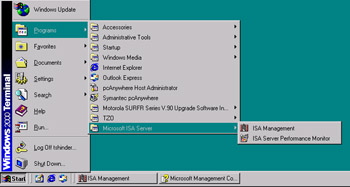
Figure 24.1: The ISA Management Programs Are Added to the Windows 2000 Programs Menu
The console can also be opened by typing the full path for the msisa.msc file (for example, C:\Program Files\Microsoft ISA Server\msisa.msc) at the Run prompt or by navigating in Windows Explorer to the folder into which ISA Server was installed and double-clicking the msisa.msc icon. The ISA Management Console is shown in Figure 24.2.
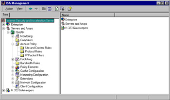
Figure 24.2: The ISA Management Console Allows You to Administer Your ISA Servers and Arrays
General procedures for working with the console are the same as with any MMC. You use the View menu at the top of the console to work with it. For example:
-
You can choose the columns to be displayed in the right detail pane by selecting View | Choose columns and adding available columns to or removing them from the display.
-
You can choose the display mode for the icons in the right detail pane by selecting Large Icons, Small Icons, List, or Details from the View menu.
-
You can select either the Taskpad or the Advanced view.
-
You can customize the console by selecting the elements that will be displayed or hidden.
A big advantage of the MMC interface is the ability to create custom MMCs that incorporate the specific snap-ins that you—or an assistant administrator to whom you delegate administrative duties—need to work with.
Adding ISA Management to a Custom MMC
To create a custom MMC to which you can add whichever administrative tools you desire as snap-in modules, you first create an empty console by typing mmc at the Run prompt. The new empty console root window will be encapsulated in a larger window for which the menu bar includes the Console, Window, and Help menus. You can add ISA management by selecting Add/Remove Snap-in from the Console menu. When ISA Server is installed on the machine, the ISA Management snap-in will be available to add to custom consoles, as shown in Figure 24.3.
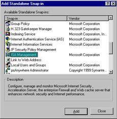
Figure 24.3: ISA Management Can Be Added to a Custom MMC
When you elect to add the ISA Management module, you will be asked to choose whether to connect to the local server, another stand-alone server, or the enterprise and arrays, as shown in Figure 24.4.
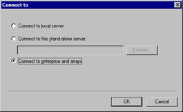
Figure 24.4: When Adding ISA to a Custom Console, You Must Choose from Three Connection Options
You will see the same console tree as in the preconfigured ISA Management tool. You can now add other snap-ins to allow you to perform a set of related administrative tasks, all from the same MMC. For example, in the MMC shown in Figure 24.5, you can manage your ISA Server array, the local certificate authority (CA), and IIS, all from the same custom console.
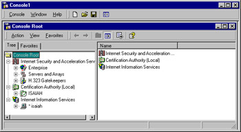
Figure 24.5: ISA Management Can Be One of Several Components in a Custom MMC
The custom console can now be saved with a unique name. By default, it will saved in the Administrative Tools folder in the Programs menu, in the profile of the currently logged-on administrator, and can subsequently be started from the Start | Programs | Administrative Tools menu.
Console Mode Options
Your custom console can be saved in one of four modes:
-
Author mode Allows you to create new consoles or modify existing consoles.
-
User mode—full access Provides full window management commands and full access to the console tree but prevents adding or removing snap-ins or changing console properties.
-
User mode—limited access, multiple window Allows use of multiple windows.
-
User mode—limited access, single window Limits access to a single window.
You specify the console mode by selecting Options from the Console menu. Regardless of the default mode in which the console is saved, it can be opened in author mode by typing the full MMC pathname with the /a switch at the Run prompt.
The Components of the ISA MMC
In this section, we look at the components of the ISA MMC and explain the function of each, including:
-
The MMC window
-
The menu bar
-
The toolbar icons
-
The console root and tree
The MMC Window
If you have created a custom console, you'll see a window within a window, as shown earlier in Figure 24.5. The outer window contains the main menu bar and the main toolbar common to all MMCs. The inner window is the console window and includes a menu bar, toolbar, description bar, and status bar. You can hide any of these elements by selecting Customize from the View menu and checking the check boxes of those elements you want displayed and unchecking those you want to hide, as shown in Figure 24.6.
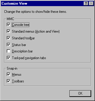
Figure 24.6: You Can Select the MMC Elements You Want to Display or Hide
The console window of the ISA MMC contains a tab labeled Tree, which displays in the left console pane the hierarchy of your ISA management components. In the section "The Console Root and Tree," we look at these elements and how they are used in administering your ISA server or array.
The right console pane displays the details of the left pane element that is selected. For example, when you select Policy Elements in the left pane, those policy elements that appear under that container in the left console tree will be displayed in the right pane, as shown in Figure 24.7.
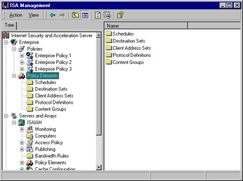
Figure 24.7: The Right Detail Pane Displays the Child Objects of the Selected Object in the Left Console Tree
Note that in Figure 24.7, there are three containers under the root:
-
Enterprise
-
Servers and Arrays
-
H.323 Gatekeepers
If the ISA server is a stand-alone server that is not a member of an array, only the last two objects will appear under the root; there will be no Enterprise object (as shown in Figure 24.8).
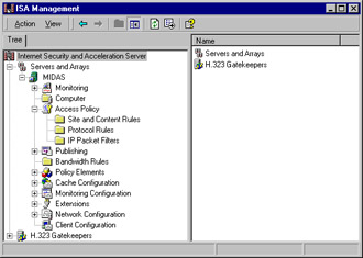
Figure 24.8: A Standalone ISA Server Has No Enterprise Object in the Left Pane
| Note | The H.323 Gatekeepers object will appear here only if you specified that it be installed during the ISA Server installation process. |
Observing the objects that appear in the left pane is one way to determine quickly, by a glance at the ISA MMC, whether the server is a stand-alone server or an array member.
The Menu Bar
The menu bar consists of two menus: Action and View. The contents of the Action menu depend on whether the ISA server is an array member and which object is highlighted in the console pane. The contents of the Action menu will be the same as the contents of the right context menu when you highlight the specified objects.
For example, the Action menu for an ISA server that belongs to an array provides the following options when the array or server object is highlighted:
-
The Set Defaults selection on an ISA server that is a member of an array allows you to elect to use the array policy only or to use an Enterprise policy. If you choose the latter, you can designate which Enterprise policy is to be used by selecting from a drop-down box. You can also choose whether to allow array-level access policy rules that will restrict enterprise policy, whether to allow publishing rules, and whether to force packet filtering on the array.
-
Use the Back Up selection to select a location for backing up the ISA configuration information.
-
The Restore selection is used to restore the configuration from backup.
-
The Refresh selection refreshes the contents of the console window.
-
The Export List selection allows you to save the contents of the detail pane to a text file. You can choose from four formats: Text (tab delimited), Unicode Text (tab delimited), Text (Comma Delimited), and Unicode Text (Comma Delimited). The first two formats are saved with the .TXT extension; the last two are saved with the .CSV extension. The text files can be imported into a spreadsheet program such as Excel or a database program such as Access for data sorting and processing.
-
The Properties selection allows you to set the security (DACL permissions) on the object and specify whether to allow inheritable permissions from the parent object to propagate to this one. The Advanced button allows you to edit permission entries, set auditing on the object, and view or change ownership of the object. These are the standard Windows 2000 access control settings.
-
The Help selection invokes the ISA Help file, which is stored in the directory in which you installed ISA Server (Program Files | Microsoft ISA Server by default) as ISA.CHM.
If the ISA server you are managing is a stand-alone server instead of an array member, the Action menu will still include the Refresh, Export List, and Help selections, but it will include none of the others listed previously. It will have one additional selection, Connect to. This option is used to connect to another stand-alone server or to an enterprise or array, as shown in Figure 24.9. Note that you cannot connect to an array from a stand-alone server.
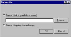
Figure 24.9: From a Stand-Alone ISA Server, You Can Connect to Another Stand-Alone Server
The View menu is identical for both stand-alone servers and array members. It contains the Choose Columns option that allows you to specify the column headers that will be displayed in the right detail pane. The choices available depend on which object you have highlighted in the left console tree. For example, if you have highlighted Servers and Arrays in the left pane, you will see a list of columns as shown in Figure 24.10.
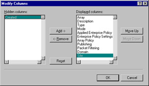
Figure 24.10: You Can Choose the Columns to Display or Hide in the Right Detail Pane
By default, all but one of the available columns is displayed. You can remove columns from the display by clicking the Remove button or add them by clicking Add. The Reset button will return the selection to the default setting.
You can select from the View menu the way you want the items in the right detail pane displayed, in keeping with the usual Windows Explorer views:
-
Large icons
-
Small icons
-
List
-
Detail
The Detail view is the default. You can also elect to use the Taskpad or Advanced view. The Taskpad view is the default, although many administrators are likely to opt for the Advanced view.
| Note | The screenshots of the ISA Management Console in this book, except for those specifically illustrating the use of the Taskpad, are shown in the Advanced view. |
The Taskpad view provides a more graphical interface for navigating the management options and configuring various elements of ISA Server. The Taskpad view uses a tabbed format that some administrators find more appealing than the standard detail pane. An example of the Taskpad view, with Servers and Arrays selected in the left pane, is shown in Figure 24.11.
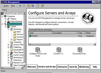
Figure 24.11: The Taskpad View Provides a More Graphical, Tabbed Interface
The same element selected (Servers and Arrays) with the Advanced view is shown in Figure 24.12. As you can see, the Taskpad view offers a more intuitive interface, whereas the Advanced view is simpler and less cluttered. Each administrator will make the choice of view based on personal preference.
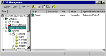
Figure 24.12: The Advanced View Provides a Simpler, Less Cluttered, Less Intuitive Interface
The last choice on the View menu is Customize, which allows you to customize the display by hiding certain MMC elements, as discussed earlier.
The Toolbar Icons
Seven icons appear on the ISA MMC main toolbar. These icons are standard navigation tools or items that mirror the functions of menu items. They include:
-
Back and Forward buttons to return to previous locations in the console tree.
-
The Up One Level button that takes the focus up a level in the console tree.
-
The Show/Hide Console Tree/Favorites button that can be used to hide the left console pane, displaying only the right detail pane across the whole window.
-
The Refresh button that, like the same choice on the Action menu, refreshes the display.
-
The Export List button that performs the same function as the same selection on the Action menu.
-
The Help button that invokes the ISA Server Help file.
Note that unlike the menu or toolbar for an application window, the MMC menu and toolbar cannot be customized.
The Console Root and Tree
The console root is the top-level object in the left pane of the ISA MMC. All objects under it are child objects of the root. Together, the root and its child objects make up the console tree. The console tree is the heart of the ISA Management Console, providing all the objects that can be configured.
The ISA Console Objects
If your ISA server belongs to an array, the first second-level object under the Internet Security and Acceleration Server root is the Enterprise container.
| Note | If you have worked with Windows 2000's Active Directory, you'll remember that a container object is an object in the tree inside of which other objects can reside. |
The Enterprise Object
The Enterprise container holds two child container objects:
-
Policies
-
Policy elements
The Policies object will hold any Enterprise policies that have been configured. By right-clicking an enterprise policy object in the left pane and selecting Properties, you can assign the policy to be explicitly applied to an array by checking the check box, as shown in Figure 24.13.
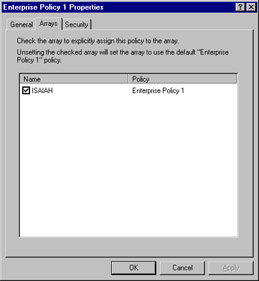
Figure 24.13: Enterprise Policies Are Explicitly Assigned to Arrays Via the Arrays Tab on Their Properties Boxes
More information about the policy is shown in the right detail pane when you select the policy name in the left pane. As shown in Figure 24.14, this information includes the policy name, type, scope, action, protocol, schedule, source, destination, and content.
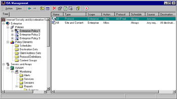
Figure 24.14: Information about Each Enterprise Policy Is Shown in the Right Detail Pane
By right-clicking the policy row in the right detail pane and selecting Properties, you can configure the following:
-
Enabling the policy
-
The policy action (allow or deny requests)
-
The protocol(s) to which the rule applies:
-
All IP traffic
-
Selected protocols
-
All IP traffic except selected protocols
-
-
The schedule for applying the rule:
-
Always
-
Weekends
-
Work hours
-
A new, custom schedule
-
-
Requests to which the rule should be applied:
-
Any request
-
Requests from specified client addresses
-
-
Requests from specified users and groups
You can determine which Enterprise policy has been applied by checking the icons in the right detail pane. The icon with a check mark indicates that the policy is applied. See Figure 24.15 for an illustration of this concept.
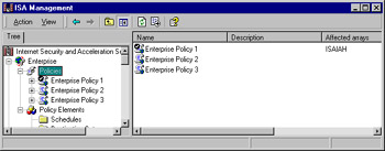
Figure 24.15: A Check Mark in the Right Detail Pane Indicates the Policy That Is Applied
Note that in Figure 24.15, Enterprise Policy 1 displays the icon with the check mark and thus is the policy that is applied.
The enterprise Policy Elements container has five child objects:
-
Schedules Specify when the rule will be in effect; can be applied to site and content rules, protocol rules, or bandwidth rules.
-
Destination Sets One or more destinations (computer, IP address or IP range, path); can be applied to site and content rules, bandwidth rules, Web publishing rules, or routing rules.
-
Client Address Sets One or more computers; can be applied to site and content rules, protocol rules, bandwidth rules, server publishing rules, or Web publishing rules.
-
Protocol Definitions Used to create protocol rules or server publishing rules (inbound protocol definitions). Application filters can include protocol definitions as well.
-
Content Groups Used to specify MIME types and filename extensions; apply only to HTTP and tunneled FTP traffic that goes through the Web proxy service.
The policy elements must be configured before the policies are configured. There are policy elements for both the enterprise policy and each array policy.
| Note | Remember that when an enterprise policy is used in conjunction with array policies, the array policy can only impose further restrictions; it cannot be less restrictive than the enterprise policy. |
When you use array and enterprise policies together, array-level rules can be applied to enterprise-level policy elements. This means that when you create a policy element at the enterprise level, it appears as a selection when you create a new rule at the array level. Let's look at how this works.
In Figure 24.16, you can see that we have created a custom schedule policy element at the enterprise level (displayed along with the two preconfigured schedule policy elements in the right detail pane).
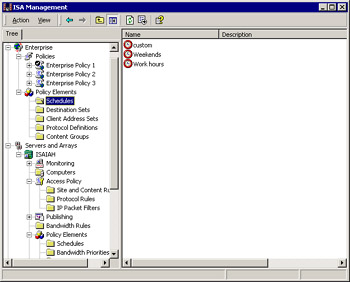
Figure 24.16: An Enterprise-Level Policy Element Named Custom Has Been Created
Now, if we go down to the array level (under the Servers and Arrays object) and, in the Site and Content Rules under Access Policy, we create a new rule, the wizard will walk us through the steps of creating our new rule. If we choose to apply the rule based on time ("Deny access only at certain times"), we will find in the drop-down box of schedule policy elements the custom schedule that we created back at the enterprise level (see Figure 24.17).
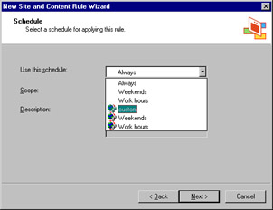
Figure 24.17: The Policy Element Created at the Enterprise Level Is Available to Be Applied to Rules at the Array Level
The Servers and Arrays Object
In the console tree, under Servers and Arrays, you will find a child object for each array, identified by the array name. By default, the array name is the same as the name of the first server that joins the array. However, you can change the array name (and you might want to do so, to avoid confusion) by right-clicking it, selecting Properties, and typing in the new array name, as shown in Figure 24.18.
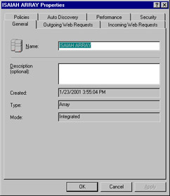
Figure 24.18: You Can Change the Array Name to Avoid Confusion with a Server by the Same Name
The array's Properties sheet also provides, on the General tab, information regarding the date and time the array was created and the mode in which its servers are installed (firewall, caching, or integrated).
The other tabs are used for configuration of outgoing and incoming Web requests, publication of autodiscovery information, and performance tuning as well as incoming Web requests, selection of enterprise policy settings for the array, and setting security permissions on the array object. (Object permissions are discussed later in this chapter, in the section titled "Performing Common Management Tasks.")
Under the Array object, you will see the following child objects:
-
Monitoring
-
Computers
-
Access Policy
-
Publishing
-
Bandwidth Rules
-
Policy Elements
-
Cache Configuration
-
Monitoring Configuration
-
Extensions
-
Network Configuration
-
Client Configuration
If you expand the Monitoring object, you will see four folders: Alerts, Services, Sessions, and Reports. Note that the Alerts object is used to view alerts; they are actually configured using the Alerts object, which is a child of the Monitoring Configuration object lower in the tree.
The Services child object contains ISA services on all servers in the array (the firewall service, Web proxy service, and scheduled content download service), indicating whether they are running or stopped, as shown in Figure 24.19.
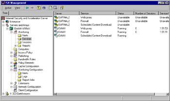
Figure 24.19: The Services Folder Contains Information about ISA Services on All Servers in the Array
Note that, as shown in Figure 24.19, if a member of the array is offline, the status of its services will be displayed as "Unavailable."
The Sessions folder contains information about current sessions that are active for the Web proxy or firewall service, as shown in Figure 24.20.
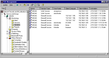
Figure 24.20: Active Sessions Are Displayed in the Detail Pane When You Select the Sessions Folder
The Reports folder contains the results of report jobs that have been configured under the Monitoring Configuration object. These are further divided into five categories, or subfolders:
-
Summary
-
Web Usage
-
Application Usage
-
Traffic & Utilization
-
Security
You can view a report by double-clicking it in the right detail pane (see Figure 24.21).
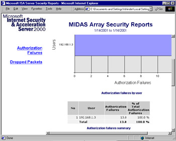
Figure 24.21: You Can View Reports by Double-Clicking the Report Name in the Right Detail Pane
You will learn how to configure alerting, logging, and reporting later in this chapter, in the "Using Monitoring, Alerting, Logging, and Reporting Functions" section.
The next object in the console tree is the Computers folder, which contains an object for each computer that belongs to the array. By double-clicking a computer object in the right detail pane, you can display its Properties sheet, as shown in Figure 24.22.
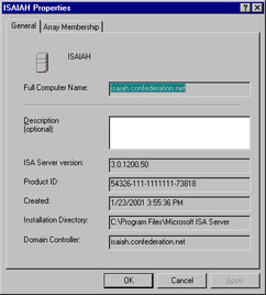
Figure 24.22: Access the Properties Sheet for Each Array Member through the Computers Folder
| Note | Although the ISA Management Console allows you to change the name of an array, it does not support changing the name of an ISA Server computer. |
In addition to general information such as the version number of ISA Server that is installed, the product ID, the date the ISA server was created, the installation directory path, and the domain controller, the Properties sheet has a tab labeled Array Membership. This tab shows the IP address used for intra-array communication and lets you specify the load factor for the server, which indicates its relative availability for caching in comparison to the other servers in the array. You can increase or decrease the load on a particular ISA server by increasing or decreasing the value in the load factor field. By default, this value is set to 100.
| Note | The intra-array IP address information is typically the same address used by downstream clients and ISA servers to communicate with the server. Microsoft recommends that you not change this value, because it has to be replicated to all the other servers in the array. However, if you do need to change the address, you can do so by typing the new IP address into the box on the Array Membership tab. The address that you use for intra-array communication must be configured to listen for requests on the same port as the address that is configured to listen for incoming Web requests. Otherwise, CARP will not function for incoming Web requests. This means you should set the incoming Web request properties for the array so that the same listener configuration is used for all IP addresses. |
Continuing down the console tree, you will find the Access Policy object, which has three subfolders:
-
Site and Content Rules
-
Protocol Rules
-
IP Packet Filters
If you have an array, you can create access policies at the enterprise level, the array level, or both. If the enterprise policy settings are configured to use enterprise policy only, you cannot add new rules at the array level. Conversely, if settings are configured to use array policy only, no enterprise policy will be applied to the array. If the enterprise administrator has configured settings for combined enterprise and array policy, an array policy will be added to the enterprise policy, with the enterprise policy overriding the array policy so that restrictions imposed by the enterprise policy will always apply. You can impose additional restrictions with the array policy but, as discussed previously, you cannot set an array policy that is less restrictive than the enterprise policy. If you configure settings to use enterprise policies only, you will not be able to use array policies without reinstalling ISA Server.
The next object in the tree is the Publishing object, containing two folders:
-
Web Publishing Rules
-
Server Publishing Rules
You can create a new rule of either type by right-clicking the appropriate folder and selecting New from the right context menu. This action invokes a wizard (see Figure 24.23), which will walk you through the steps required to create the new rule.
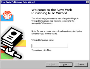
Figure 24.23: New Web Publishing or Server Publishing Rules Are Created with a Wizard
The Bandwidth Rules object is the next element in the console tree. Bandwidth rules let you specify which connections have priority over other connections.
| Note | Don't confuse bandwidth priority rules with bandwidth limitation. ISA Server rules do not limit the amount of bandwidth that can be used by a connection; they specify how the QoS packet-scheduling service should prioritize the use of multiple network connections. |
As with the creation of other rules, a New Bandwidth Rule Wizard assists you in creating bandwidth rules.
Policy elements come next in our journey down the left console pane. You will recognize most of these as the same as the policy elements available under the Enterprise object. However, there are two additional folders here: the Bandwidth Priorities element and the Dial-up Entries element.
Moving down the tree, we come to the Cache Configuration object. You will find two subfolders here:
-
Scheduled Content Download
-
Drives
The scheduled content service is w3prefetch, which lets you configure ISA to download cache content from specific URLs at specified times. This prefetching of regularly accessed pages speeds your users' access because the pages are already in the cache when users attempt to access them. For example, if users visit a particular news site daily, you could configure a scheduled download to occur on a daily basis so that the content in the cache would be updated each day.
| Warning | You cannot schedule a content download job if the Web server on which the Web objects reside requires client authentication. The job will fail because the Web server cannot authenticate the ISA server. |
You create scheduled content jobs by right-clicking the Scheduled Content Download folder and selecting New | Job, which invokes another wizard. After giving the job a name, you can set the date and time to start the download and specify whether to download the content just once, daily, or weekly on a specified day of the week. You will be able to choose the URL from which the content should be downloaded and whether to download only content from the URL domain, not from sites to which it is linked. You also have the option of caching dynamic content, even when the HTTP cache control headers indicate they are not cacheable.
You can limit the depth of links to be cached as well. By default, there is no limit. You can also set a limit on the total number of objects to be cached, up to a maximum of 99,999.
When you have completed providing the information for the wizard, a summary of your selections will be presented, as shown in Figure 24.24.
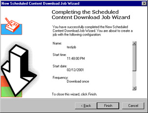
Figure 24.24: The Scheduled Content Download Wizard Makes It Easy to Create a Job to Automatically Update the Cache of Specified URLs
Now the job is displayed in the right detail pane along with other scheduled jobs, as shown in Figure 24.25.
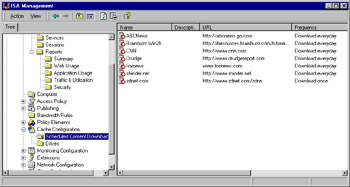
Figure 24.25: Scheduled Content Download Jobs Appear in the Right Pane When the Folder Is Selected
The Drives folder displays NTFS logical drives on the ISA servers in the array, provides information on the total amount of disk space and the amount of free space on each drive, and allows you to set a limit on the cache size, in megabytes, for each drive. Right-click the drive in the right detail pane to access the Properties sheet shown in Figure 24.26.
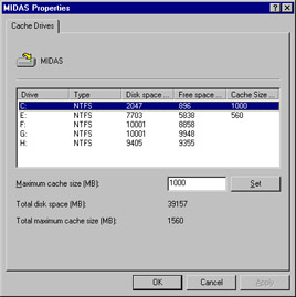
Figure 24.26: Configure the Amount of Disk Space on Each NTFS Drive to Be Allocated to the ISA Cache
Continuing to move down the left console tree, you will see the Monitoring Configuration object that holds folders for Alerts, Logs, and Report Jobs. Later in this chapter, in the "Using Monitoring, Alerting, Logging and Reporting Functions" section, you will learn how to use each of these objects.
The next item in the tree is an object labeled Extensions. Extensions are filters that provide additional functionality for filtering applications and Web requests. Thus there are two types of filters: application filters and Web filters. Several filters of each type are installed with ISA Server, but additional filters can be developed by third parties to be used with ISA Server.
The Network Configuration object is used to set up a local or remote ISA VPN server and allow VPN client connections. These setups are done with a series of wizards that make it easy to configure ISA VPNs.
There are three subfolders under Network Configuration:
-
Routing Used to create and configure routing rules (using the Routing Rule Wizard).
-
Local Address Table (LAT) Used to construct a local address table and to add entries to the existing LAT.
-
Local Domain Table (LDT) Used to add new entries to the LDT.
Routing rules determine where Web proxy client requests are sent and apply to both incoming and outgoing Web requests. The local address table keeps track of the internal IP address ranges that are in use by the LAN behind the ISA server. ISA users the LAT to control communication between internal computers and those on external networks; the LAT is automatically downloaded to firewall clients, copies of which are periodically updated.
The local domain table lists all domain names in the internal network behind the ISA server and is used by firewall clients to differentiate between internal and external names. Clients use the LDT to determine whether to send a name resolution request to ISA Server to handle the name resolution for an external resource or to perform name resolution themselves for a local resource.
| Note | The LDT is not used by SecureNAT clients, which resolve both internal and external names via DNS and thus must have access to DNS servers. |
As we move down the console tree, we next encounter the Client Configuration object. As shown in Figure 24.27, there are two configuration objects in the right detail pane: Web Browser and Firewall Client.
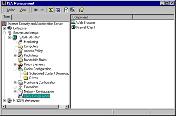
Figure 24.27: The Two Client Configuration Objects: Web Browser and Firewall Client
By double-clicking the configuration object name, you can access its Properties sheet, allowing you to view or change settings.
The Web browser Properties sheet allows you to choose whether to configure the Web browser during firewall client setup and whether to use automatic discovery and configuration. You can also choose to have the client bypass the proxy for local servers and/or directly access computers specified in the LDT, and you can specify the IP addresses, domain names, or computer names of specific computers that you want the client to be able to access directly, without going through ISA. You can also configure a backup route, designating how clients should access the Internet if the ISA server is unavailable.
| Note | Like most firewalls, it is the gatekeeper of network traffic. You need to define what's trusted and not trusted to go through the ISA server. The LDT provides an interface for this. |
The Properties sheet for the firewall client is less complex. It allows you to specify whether the firewall client will connect to the ISA computer or array by name or IP address (and enter the DNS name or IP address of the ISA server to be used), and you can enable or disable autodiscovery in the firewall client. The Application Settings tab is used to add client configuration information for specific applications, if necessary.
| Note | The default firewall client configuration works for the majority of Winsock applications, but in some cases, custom client configuration information needs to be stored in the Mspclnt.ini or Wspcfg.ini file. |
The H.323 Gatekeepers Object
The last second-level object in the console tree is the H.323 Gatekeepers object. By right-clicking this object, you can add a gatekeeper computer (either on the local machine or on a remote computer identified by fully qualified domain name) and view and configure active terminals, active calls, and call routing (see Figure 24.28).
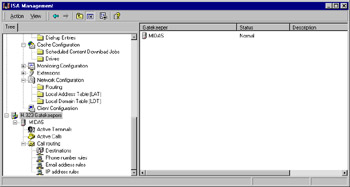
Figure 24.28: Add and Configure H.323 Gatekeepers Via the Last Second-Level Object in the Console Tree
The H.323 Gatekeeper is used to allow clients to use NetMeeting and other H.323-compliant applications through the ISA server. The clients register a well-known alias (typically an e-mail address) with the gatekeeper, which allows others to contact them. The gatekeeper provides directory services and call routing for registered clients. All inbound calls to a well-known alias via these programs require registration with the gatekeeper. Outbound calls require only that clients are registered if they are using translation services; other outbound calls can be made without using the gatekeeper.
Understanding the H.32X Series Standards
The H.323 ITU standard for audio, video, and data communication across IP networks that do not provide QoS is part of a series of standards that all work to enable videoconferencing across disparate networks. The series is known collectively as the H.32X standards. H.320 provides specifications for using ISDN, and H.324 addresses the Public Switched Telephone Network (PSTN), also referred to in the industry as POTS, or plain old telephone service.
H.323 applies to both voice-only and full audio-videoconferencing. An advantage of the H.323 standard is that it allows communication over existing IP-based networks without any modifications to the network infrastructure. H.323 supports management of network bandwidth, allowing administrators to restrict the amount of bandwidth that can be used for conferencing or specify a maximum number of H.323 connections active on the network at any one time. H.323's support for multicasting also decreases bandwidth requirements. Platform independence means that users can communicate with one another using a variety of hardware platforms and operating systems.
The H.323 standard designates four major elements: terminals, gateways, gatekeepers, and multipoint control units (MCUs). The terminal is the endpoint for real-time two-way communication with another terminal or a gateway or MCU. H.323 terminals also must support H.245. The latter negotiates channel usage and capabilities. Gateways provide translation functions between the H.323 endpoints and other types of terminals. Gateways are optional components; if both endpoints are on the same LAN, they are not needed. Gatekeepers function as the central point for call control services to registered endpoints in their zones. Gatekeepers provide address translation from terminal or gateway aliases to IP addresses. Gatekeepers can also manage bandwidth and route H.323 calls. A gatekeeper's zone refers to all the terminals, gateways, and MCUs that are managed by that gatekeeper. An MCU enables conferencing between multiple (three or more) endpoints (as opposed to simple one-to-one communication). The MCU is made up of two components: the multipoint controller (MC) and the multipoint processor (MP).
ISA Wizards
Following in the footsteps of Windows 2000, ISA Server provides a variety of wizards to assist you in setting up services, configuring features, and performing other common tasks. A wizard is a series of "friendly" dialog boxes that walk you through a process in a step-by-step fashion.
The Getting Started Wizard
The Getting Started Wizard is available when you start ISA Server after installing the ISA software. The wizard is designed to help you configure your initial array and enterprise policies. Steps include:
-
Configuring enterprise policy settings and enterprise-level policy elements, protocol rules, and site and content rules (if you have installed an array rather than a stand-alone ISA server)
-
Creating array-level policy elements, protocol rules, and site and content rules
-
Setting the system security level
-
Configuring packet filtering
-
Configuring routing and chaining
-
Creating a cache policy
Rules Wizards
After ISA Server is installed, you can create and configure new rules (routing rules, protocol rules, site and content rules) using the Rules wizards that are invoked when you right-click the rule type under Access Policy or Network Configuration and select New | Rule.
One of the handiest aspects of the ISA wizards is the screen that appears after you finish entering the information requested by the wizard. This page summarizes the information you have entered, so you can double-check for accuracy before you click Finish to actually complete the process (see Figure 24.29).
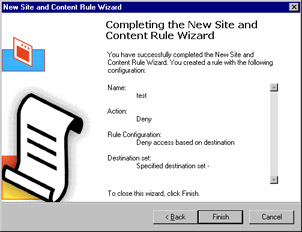
Figure 24.29: The ISA Wizards Allow You to Check the Information Entered for Accuracy Before You Click Finish
These rules wizards make it easy for you to create a new rule, but you can change the properties of the rule later by accessing the rule's Properties sheet; double-clicking the rule in the right detail pane to do so.
VPN Wizards
ISA includes three wizards to help you perform tasks related to setting up VPN connections:
-
The Local ISA VPN Wizard Used for configuring the ISA server that will receive inbound VPN connections (the VPN server) or to set up the local ISA server to initiate VPN connections.
-
The Remote ISA VPN Wizard Used to set up a remote ISA server to initiate or receive connections.
-
The Set Up Clients to ISA Server VPN Wizard Enables roaming clients to connect to a VPN server.
|
EAN: 2147483647
Pages: 240
- Challenging the Unpredictable: Changeable Order Management Systems
- ERP System Acquisition: A Process Model and Results From an Austrian Survey
- Intrinsic and Contextual Data Quality: The Effect of Media and Personal Involvement
- A Hybrid Clustering Technique to Improve Patient Data Quality
- Development of Interactive Web Sites to Enhance Police/Community Relations