Basic System Configuration, Out of the Box
|
Once the initial system is configured, your Nokia runs a minimal installation of Apache Web server, and the server runs on the standard port 80 by default. IPSO 3.3 through IPSO 3.6 FCS3 use Apache/1.3.6. You can view the Apache version on your Nokia by running the command /bin/httpd –v. This server is running for the purpose of serving out the Web pages necessary for you to configure your Nokia Security Platform (NSP) using the Nokia Voyager Web interface.
You always have the option of running the Voyager interface using the lynx text browser through a console connection, but once you have assigned an IP address to your Nokia, you will be able to connect with any Web browser on the network to configure the system. Although Lynx is a useful tool, many administrators prefer the nicer Voyager GUI available through a graphical Web browser.
| Note | Remember to save your configuration changes using the Save icon within your Voyager GUI if you want to save any changes you make to the system. At every configuration screen in the Voyager interface, you will see icons at the top and bottom of each page that give you the options to go Home, Up, Top, Apply, or Save. After every change that you apply to the system, the change takes effect immediately, but you must select Save to write your changes to the /config/active file if you want changes you make to be preserved through a reboot of the system. |
Front Screen
When you went through the initial configuration, you set up your internal interface with the Nokia. Now you can begin configuring your appliance by typing in the IP address of this interface in a Web browser such as http://10.10.10.10 or using a DNS-resolvable name instead of an IP address, if available. Next enter the admin username and password when prompted for authentication. This step brings you to the front screen of the Voyager interface, which should resemble the image in Figure 19.1.
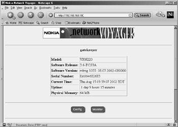
Figure 19.1: The Voyager Front Screen Display
You should notice that some very important system information is listed on this initial screen, such as the Nokia's model, software release, and version, as well as the serial number, which you'll need when you call in a support or maintenance request. The information on this front screen is the same regardless of the Nokia model you possess. To continue from this initial screen, select Config, to enter the main configuration screen (see Figure 19.2). This screen gives you all the possible options for configuring your NSP. In versions previous to IPSO 3.6, this screen looks slightly different, but most of the options are the same. From the initial screen, select Monitor to enter a read-only area, which allows you to view system status and other interesting information about the system.
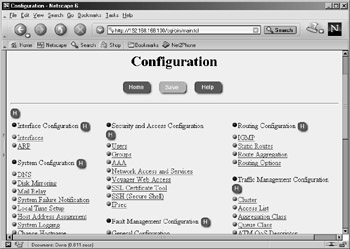
Figure 19.2: The Main Configuration Screen
Navigating Voyager
When you are moving around within the Voyager interface, it is important that you do not use your browser's Back button to return to a previous screen. If you do this, you could end up getting cached pages that display incorrect information, which can cause confusion and possible misconfiguration. Instead, use the buttons that are provided for navigation across the top and bottom of each screen. These buttons and each of their functions are as follows:
-
Home Displays the front screen.
-
Top Displays the main Configuration screen or main Monitor screen, depending on which you are working under.
-
Up Displays the previous page.
-
Apply Applies changes entered on that page.
-
Save Saves all changes that have been applied to the system, since either the last save or the last reboot.
-
Help Displays help documentation relevant to the current page.
You will also see several small help buttons available throughout the various screens. You can identify these by the blue, circular icon with a white H displayed in the center. Each one gives you detailed help information for each section in which the button is displayed. This help feature pops up in a separate browser window, so you don't lose your current place within the Voyager interface.
If you installed the documentation package available for your version of IPSO, a Doc button is available along with the other navigation buttons on each page. This documentation provides even more help for each section of the configuration. In IPSO 3.6, there is even a CLI Reference Guide to assist you in using the new Command Line Interface Shell (CLISH) tool. In the documentation, select the Content button at any time to see a list of available topics.
Configuring Basic Interface Information
When configuring interfaces, you should know what IP address and netmask you will assign each interface in advance. For the examples that follow in this chapter, let's assume that you have a simple Nokia firewall with three interfaces: external (Internet facing, routable IP), internal (nonroutable IP), and SSN (nonroutable IP). Assume an upstream router owned by the ISP that provides the Internet circuit as your default gateway.
In this section, we walk you through the process of configuring an Ethernet interface on your NSP. You will learn how to add or delete an IP address to an interface, manually set the speed and duplex, and check the status of your interfaces.
IP Addresses
When setting up the internal and secure server network (SSN or DMZ) interfaces, you should choose a network subnet within the Internet Assigned Numbers Authority (IANA) reserved IP address space, which are outlined in RFC 1918.
Adding an IP Address to an Interface
Follow these steps to configure an interface on your Nokia platform:
-
Bring up the Voyager Web interface via http in your Web browser.
-
Click Config.
-
Click Interfaces, the first link in the first column under the main Configuration screen. You will see the Interface Configuration page displayed as in Figure 19.3. This table shows you all your available interfaces along with their current status and configuration options.
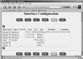
Figure 19.3: The Interface Configuration Screen -
Select the logical interface to which you will assign an IP address. In our example, we'll select eth-s4p1c0, the second Ethernet interface listed in the table in Figure 19.3.
-
Click the toggle button to On to make the interface active, and type in the new IP address and mask length in your browser. All netmasks configured through Voyager will be in aggregate or bit mask format. For example, 255.255.0.0 is a 16-bit mask, so to set that mask on an interface, you would type 16 for the mask length. There is a good netmask cheat sheet at http://noc.mwci.net/info/netmask.shtml, which might help you convert a netmask in dotted quad notation to the aggregate, and vice versa. Or, if you have Check Point Next Generation Security Administration by Syngress Publishing, Inc. (ISBN 1-928994-74-1), you'll find a cheat sheet in Appendix A.
-
Optionally, you can change the logical name of the interface from the default eth-s4p1c0 to a name that might make it easier to identify, such as either internal or external. The default name of the interface might not be easy to read, but it helps you identify the interface you are configuring on the Nokia. For example, eth-s4p1c0 is the Ethernet interface in slot 4, port 1. These numbers vary depending on how many interfaces you have installed and which you are configuring. See Figure 19.4 for an example interface configuration before you go on to the next step.
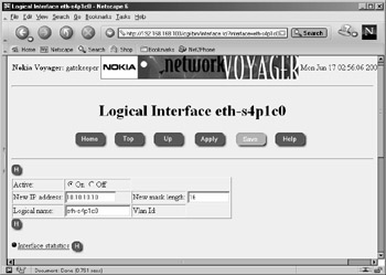
Figure 19.4: Configuring IP Addresses -
Click Apply. Once you apply your changes, they take effect immediately.
-
Click Save. You must save your configuration if you want your settings to be retained after a reboot. If you forget to save your changes, you need to start all over again after you reboot the system.
-
Click Up to return to the previous interface configuration screen. You should see your new interface entered into the table that we first saw in Figure 19.3.
Deleting an IP Address from an Interface
Once you have set the new IP address on an interface and apply the changes, you will see the Logical Interface page displayed, as in Figure 19.5. Notice that next to the IP address, you have a check box labeled delete. To remove this IP address from eth-s4p1, follow these three easy steps:
-
Click the delete check box.
-
Click Apply.
-
Click Save.
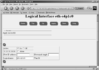
Figure 19.5: An Applied Interface Address
Voyager's /config/active File
The /config/active file contains all the system configuration information. Actually, /config/active is a symbolic link that points to the file /config/db/initial. If you attempt to make a change on the command line (for example, with ifconfig), these changes will be lost when the system is restarted. The safest way to make persistent modifications on your Nokia is to use either the Voyager Web interface or the CLISH, which is a new tool in IPSO 3.6. To use CLISH, simply type clish at the command prompt, and you will be presented with a Nokia> prompt.
You'll need to use one of these tools when you edit config files in /etc as well (for example, /etc/hosts), since these files are wiped out at each boot by the /config/active settings. If you keep a backup of this file, you could restore a system configuration this way, but any package-specific configuration would not be contained here (such as Check Point FW-1 rules, objects, licenses, and so on).
Notice how anytime you need to save a change, the Save button "lights up" in Voyager. Once this button is selected, all changes applied to the system until this time will be written to the /config/active file, and the button will be grayed out again. This button is a good indicator of whether you have made any changes that need to be saved.
Finally, if you want to erase all settings on a Nokia system and start from scratch, you can remove the file /config/active, and when you reboot your Nokia, it will begin to go through the initial configuration process all over again, prompting you to enter a hostname and so on. You need to have a direct console connection to perform this task.
Speed and Duplex
Most of the Ethernet interfaces that ship with the Nokia models are 10/100MB interfaces, unless you request a Gigabit Ethernet interface in your system. If you want to see the speed and duplex at which your interface is auto-negotiating, or if you want to force these settings manually, you can do so under the Physical Interface Configuration screen.
From the Interface Configuration screen, click the link under the physical interface column that you want to configure. For our example, let's select eth-s3p1. From here you have the option to disable the interface by toggling the Active On/Off button, as seen in Figure 19.6. The Physical Status table also informs you of the type, media, maximum transfer unit (MTU), and MAC address for this particular interface.
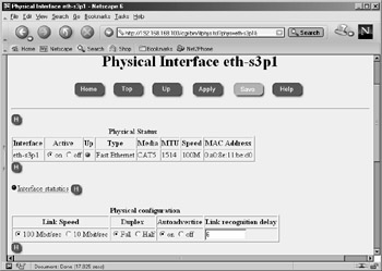
Figure 19.6: Physical Interface Configuration
Confirming Interface Status
Now that you have the interfaces configured, how do you know if they have a link? There are a few ways that you can view your interface status within Voyager or from the command line. If you have just finished interface configuration, you can see the status displayed as either Up or Down with a green ball icon or a red ball icon, respectively, as shown in Figure 19.7. You can access this page in Voyager from the main configuration screen by clicking the Interfaces link.
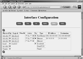
Figure 19.7: Interface Status Icons
In the Interface Configuration screen, there are two columns per interface that describe whether the interface is up or not. The first Up column relates to the physical interface. If there is a link, this icon is green; otherwise, it will be red. The second column refers to the logical state. This icon is red if the link is down, and it is green if the link is up. If you disable the interface by changing the active state to Off, no icon is displayed.
Another way you can view interface status is via the Monitor link. If you are within Voyager Configuration already, click the Home | Monitor from the front screen. From here, you can click Static Monitor | Interface under the Static Monitor heading. You should now see a page similar to the one in Figure 19.8. If you scroll down a little, you will see the interface information, which is the same information you would see if you were on the command line, typing in ifconfig –a. Compare the following output with Figure 19.9:
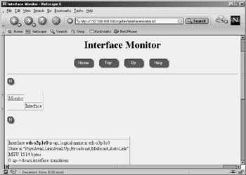
Figure 19.8: Monitoring Interfaces Screen 1
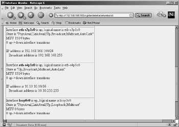
Figure 19.9: Monitoring Interfaces Screen 2
gatekeeper[admin]# ifconfig -a ser-s2p1: flags=4126<UP,POINTOPOINT,MULTICAST,PRESENT> encaps none eth-s3p1c0: lname eth-s3p1c0 flags=e7<UP,PHYS_AVAIL,LINK_AVAIL,BROADCAST, MULTICAST,AUTOLINK> inet mtu 1500 192.168.168.100/24 broadcast 192.168.168.255 phys eth-s3p1 flags=4133<UP,LINK,BROADCAST,MULTICAST,PRESENT> ether 0:a0:8e:11:be:d0 speed 100M full duplex eth-s4p1c0: lname eth-s4p1c0 flags=e7<UP,PHYS_AVAIL,LINK_AVAIL,BROADCAST, MULTICAST,AUTOLINK> inet mtu 1500 10.10.10.10/16 broadcast 10.10.255.255 phys eth-s4p1 flags=4133<UP,LINK,BROADCAST,MULTICAST,PRESENT> ether 0:a0:8e:11:be:d4 speed 10M half duplex eth-s5p1c0: flags=e0<BROADCAST,MULTICAST,AUTOLINK> phys eth-s5p1 flags=4132<UP,BROADCAST,MULTICAST,PRESENT> ether 0:a0:8e:11:be:d8 speed 10M half duplex loop0c0: flags=57<UP,PHYS_AVAIL,LINK_AVAIL,LOOPBACK,MULTICAST> inet6 mtu 63000 ::1 --> ::1 inet mtu 63000 127.0.0.1 --> 127.0.0.1 phys loop0 flags=10b<UP,LINK,LOOPBACK,PRESENT> soverf0: flags=2923<UP,LINK,MULTICAST,PRESENT,IPV6ONLY> stof0: flags=2903<UP,LINK,PRESENT,IPV6ONLY> tun0: flags=107<UP,LINK,POINTOPOINT,PRESENT>
Adding a Default Gateway
If your Nokia firewall will be routing traffic to several networks, such as the Internet, you should configure a default gateway. The default gateway is typically the next-hop router closest to the Internet, which you point to by entering a default route into the routing table. You specifically tell the device that this gateway is the default, and if a packet does not match any other entry in the routing table, it will get sent to this gateway. Typically, there should be only one default gateway in the routing table. If you are doing load balancing or failover routing, you might have more than one, but often these will be dynamic routes and not static routes.
To configure a default gateway on your NSP, follow these instructions:
-
Bring up the Voyager Web interface using http in your Web browser.
-
Click Config.
-
Click Static Routes under the Routing Configuration heading.
-
Under the Static route, Default: Gateway column, select On. Leave the next-hop type as normal. You may also fill in a description if desired (see Figure 19.10). The other options in the next-hop type are reject, which drops all packets, sending an unreachable Internet control message back to the originator, or blackhole, which drops all packets quietly without notifying the sender.
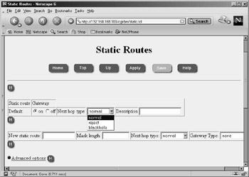
Figure 19.10: Adding a Default Gateway: Gateway Column Options -
Click Apply.
-
For Gateway Type, select address, as shown in Figure 19.11.
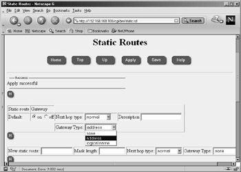
Figure 19.11: Adding the Default Gateway: Address Screen -
Click Apply again.
-
Enter the IP address of the gateway.
-
Click Apply one last time. At this point, the route is added into the system, and it will be functional, but don't forget the next step!
-
Click Save.
Now you have successfully added a default gateway to your Nokia. If you log in to the console of your Nokia and run a netstat –rn command, you should see an entry similar to the following. However, your default route might not be displayed if that interface is not physically up:
gatekeeper[admin]# netstat -rn | grep default default 10.10.1.1 CU 0 0 eth-s4p1c0 default RCU 1 0
As you can see in Figure 19.12, you have the option of setting a priority on your default route entry. This priority determines the route that will be used if there are multiple routes that are otherwise equivalent; lower-priority routes take precedence. You can enter a number between 1 and 8; however, you should know that the only time a lower-priority route will not be used is if that interface is down. So, it would not make sense to configure two routes with different priorities on the same interface. If the priorities are the same, the gateways will be treated with equal cost as multipath routes.
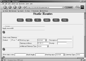
Figure 19.12: Setting Priorities on Default Gateway Route Entries
Setting the System Time, Date, and Time Zone
It's important that you set the correct time and date in your NSP so that your system and/or firewall logs will record the correct time that events have occurred and so any scheduled cron jobs will run at the time specified.
Time and Date
To manually configure the time and date, click the Local Time Setup option under the System Configuration heading on the main Configuration screen. Alternatively, you can configure Network Time Protocol (NTP), which allows you to synchronize your NSP time with the time from a NTP server, either on your network or on the Internet. The option to enable NTP is found under the Router Services heading on the main Configuration screen.
Let's start by setting the correct time zone for your region. The Nokia appliance will be configured for Greenwich mean time (GMT) out of the box. Many organizations with a global presence use GMT, which is the universal time standard. Others prefer to use a local time zone, such as Eastern standard time (EST) for those in the vicinity of New York in the United States. To select your time zone, choose a city from the list on the Time screen, displayed in Figure 19.13.
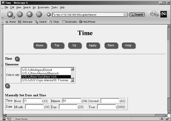
Figure 19.13: The Time Screen
Once you select the correct time zone, click Apply and then click Save. Then you can change the time, if needed, in the next section labeled Manually Set Date and Time. Simply enter the hour, minute, and/or second. If you leave any of these fields blank, the current value will not change. The current value is listed in parentheses next to each text entry box. Follow the same syntax when you change the date. Enter the month, day and/or year. The current value is displayed in parentheses next to each text box.
Configuring the Network Time Protocol
For security purposes, if you decide to set up NTP, it is probably best to synchronize to a server residing within your network. The Nokia can also be run as an NTP server. When you turn on NTP, it could take a while for the clock to update, so be patient. Bring up the NTP configuration screen, shown in Figure 19.14, by clicking NTP under the Router Services heading on the main Configuration screen.
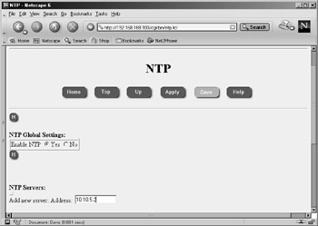
Figure 19.14: The NTP Configuration Screen
Understanding NTP
NTP is a time protocol that allows administrators to synchronize local clocks over the Internet in a distributed client/server model. This protocol uses UDP 123 for communication, and you might need to allow UDP 123 through if you are trying to synchronize time through a firewall. NTP has been around since the mid-1980s and has had a few revisions since its inception. The current version of NTP is v3, but you can utilize any of the earlier versions on your NSP for flexibility. Version 3 code has been improved to remove minor bugs found in earlier versions, but the main advantage is that it has been enhanced for maximum stability and reliability over high-speed, gigabit networks. This means that even at lower speeds, the algorithms used will be more accurate.
Once NTP is enabled, it can begin to gather time data from other servers and calculate the offset needed to correct the local clock based on the remote server's time. It's also possible for the NTP server to communicate with other servers that are considered peers and compare all their clocks so that they can have the most accurate timekeeping between them. A great deal of hard work and effort have been put into keeping the time as accurate as possible in this protocol, and several other factors are taken into consideration, such as the time lag in receiving the data and errors that could affect the transmission, depending on how far from the time source your server is located. If you would like to know more about NTP, version 3 of the protocol is detailed in RFC 1305.
Configuring NTP
Once NTP is enabled, several settings are available on the Voyager configuration screens. As you can see in Figure 19.15, you can configure multiple NTP servers with which your Nokia can synchronize. If you want to specify that one server should be preferred over the rest, simply select Yes for that server in the Prefer section.
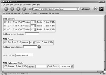
Figure 19.15: NTP Configuration Options
Another option is to set up NTP peers, which are other servers with which you want to compare your local time settings. Your local time is not used in the calculation with the NTP servers that were listed previously, but when you include peers in the configuration, your time is compared with the peer times to calculate a time that is most accurate between them.
Finally, if you want other servers to retrieve their time from you, click Yes at the bottom of the screen labeled NTP Reference Clock: NTP Master. You can enter a number from 0 to 8 in the Stratum field, which specifies the level of your NTP server in the hierarchy. Nokia recommends that you leave this at the default, 0. Your local clock will be the source of the data provided in the master state.
Configuring Domain Name System and Host Entries
Along with assigning IP addresses to all the hosts on your network, administrators will also configure DNS and host table entries on almost every PC. You might not want to set up name servers on a firewall, however, since you most likely will not be running user-facing applications directly on the box. There are some advantages to running a DNS resolver on a firewall, but there can be some major disadvantages to it as well. Configuring host entries, however, will be a necessary step on your Nokia firewall if you want to install an FW-1 license.
Since it is suggested to install your firewall while it is not plugged into any untrusted networks, it will be best to start with DNS disabled on the firewall. If you have DNS enabled and the system cannot reach its name servers, the system could become sluggish and system performance will be affected. It is important that when you do configure DNS, you configure it properly. Otherwise, if a primary name server goes down, all traffic, including your VPN connections, will be affected.
The firewall should be able to resolve its own external IP address to the name of the host computer. The Nokia platform must have the hostname associated with its external IP address for FW-1 licensing purposes as well; this is done through the Host Address Assignment link found under the System Configuration heading in the Voyager GUI. You must use this interface to configure host entries instead of editing a Hosts file. Here you should also add IP addresses for devices that your firewall might communicate with frequently, such as a management server and/or enforcement module.
Another DNS record that you should create is a pointer (PTR) record for your firewall's external IP address or any other address(es) that you will be using for Network Address Translation (NAT). Some Web sites and FTP servers require that you have a reverse resolvable IP address before they will grant you or your users access to download their files. If you have obtained a block of IP addresses from your ISP, chances are that the ISP controls the PTR records for your addresses. Sometimes they provide you with a Web site where you can administer these yourself. Other times you need to find the right person who can make the changes for you. If you have your own abstract syntax notation (ASN), you can set up your own in-addr.arpa domain and create your own PTR records.
If you will be running the FW-1 HTTP Security Server on your Nokia, enable DNS. Otherwise, the firewall will display "Unknown WWW Server" in users' Web browsers.
| Note | You will not be able to apply your FW-1 license until you have configured the host address assignment for the Nokia's external interface. When you run through the initial configuration, you usually specify an internal IP address, which is set up in the host table for you. However, most FW-1 licenses are issued on external addresses, and you must configure this setting within Voyager before the license addition is successful. |
DNS
DNS is used to resolve domain names to IP addresses, and vice versa. Behind the scenes, your PC uses DNS whenever you're using your Web browser or sending e-mail, among other things. Your Nokia device will not function as a domain name server, since the system was built as a high-performance security platform and running DNS servers on such a system doesn't make much sense. However, your device will operate as a DNS client. Most UNIX systems use an /etc/resolv.conf file to store their DNS settings, and the Nokia is no exception. However, you configure the NSP resolv.conf file via the Voyager GUI.
To configure DNS, click System Configuration | DNS on the main Configuration screen. Doing so displays the main DNS Configuration screen, similar to the one displayed in Figure 19.16.
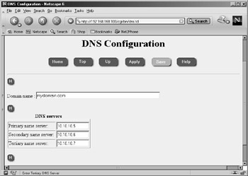
Figure 19.16: The DNS Configuration Screen
To enable DNS lookups, simply enter one or more name servers in the fields provided, then click Apply | Save. To disable DNS, delete the IP addresses listed, and then click Apply | Save. For obvious reasons, you should always use IP addresses rather than names for your name servers here. You can verify that your changes have been applied by looking at the /etc/resolv.conf file on the system:
gatekeeper[admin]# cat /etc/resolv.conf # This file was AUTOMATICALLY GENERATED # Generated by /bin/resolv_xlate on Sun Jun 23 22:51:24 2002 # # DO NOT EDIT # search mydomain.com nameserver 10.10.10.5 nameserver 10.10.10.6 nameserver 10.10.10.7
The Hosts Table
As mentioned earlier, it is necessary to configure at least one static host entry on your Nokia in Voyager. To enter this configuration screen, displayed in Figure 19.17, click Host Address Assignment under the System Configuration heading on the main Voyager Configuration screen. Once the Static Host Entries configuration page is displayed, you should see an entry for the local host on IP address 127.0.0.1, also called the loopback address. You should never remove this host entry, because the system uses it for various local operations.
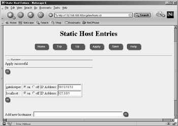
Figure 19.17: Adding a New Hostname
To add a new hostname, enter either the fully qualified domain name (FQDN) or a simple hostname in the Add new hostname field. We are using the name gatekeeper, which was the name assigned to this Nokia during initial system configuration. Next click Apply, and then enter the IP address associated with the gatekeeper. This should be the IP address that you will use if licensing the FW-1 product on your Nokia as well, and it is typically the firewall's external IP address. Click Apply | Save to complete the host address assignment.
Configuring a Mail Relay
The Nokia Security Platform will not run a mail server, but you can configure it to deliver mail by setting up a mail relay within the system configuration in Voyager. This might be useful if you want to receive important system messages from syslog, configure mail alerts within your FW-1 Security Policy, or write some custom scripst that send mail.
When you configure your mail relay, you have the option of specifying a remote user on the mail relay server. This optional field allows you to choose a specific username on the remote system that will receive all mail that is meant for "admin" or "monitor" users on the Nokia system. The default username is root:
-
To enable a mail relay in Voyager, start by clicking Mail Relay under the System Configuration heading from the main Configuration screen.
-
In the empty box next to Mail Server:, enter the IP address of the mail server you will be using. This machine should be running an SMTP server and configured as a mail relay (see Figure 19.18).
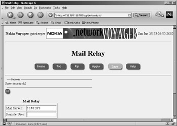
Figure 19.18: Mail Relay Configuration -
Click Apply.
-
Click Save.
Configuring System Event Notification
If you click System Failure Notification, located on the main Configuration screen under the System Configuration heading, you will be able to turn the system event notification function on or off. If this function is enabled, an e-mail will be generated to whomever you specify. Note that the mail relay must be configured for this to function. The notification e-mail will contain information such as the system hostname, software version, the location of certain crash files, and a dump trace to help identify the problem. See Figure 19.19 for a sample notification configuration. Don't forget to click Apply | Save.
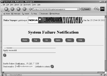
Figure 19.19: System Failure Notification Configuration
|
EAN: 2147483647
Pages: 240