Section 5.7. Network of LANs
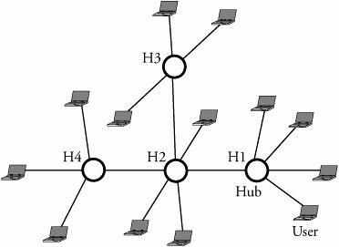
5.7. Network of LANsIncreasing the number of interconnected devices and the volume of traffic requires splitting a single large LAN into multiple smaller LANs. Doing so dramatically improves network performance and security but also introduces a new challenge: how to interconnect multiple LANs. LANs may be of different types or may have devices that are not compatible with one another. New protocols need to be developed that allow all partitions of a LAN to communicate with one another. Multiple LANs can be connected to form a college campus network. The campus backbone serves as a channel between a department and the rest of the campus network and facilitates the connection of the department to the Internet via a gateway router. The campus backbone is an interconnection of routers and switches. Servers used by an entire organization are usually located in a data bank and organization dispatching center. Devices known as protocol converters are used to interconnect multiple LANs. Depending on the level of interconnection required, layer 1, layer 2, layer 3, and layer 4 protocol converters are available. Two networks can be connected using layer 1 devices referred to as hubs and repeaters . Layer 2 protocol converters have information about the layer 2 protocols on both interconnected LANs and can translate one to the other. At layer 2, bridges and switches can carry out the task as layer 2 devices. At layers 3 and 4, routers and gateways , respectively, are used. 5.7.1. Using Repeaters, Hubs, and BridgesIn Chapter 3, we explained the operations of repeaters, hubs, and bridges. Figure 5.9 shows a situation in which bus LANs are interconnected through repeaters. Users A G are connected to multiple Ethernet LANs. Users of these networks are aware of the existence of repeaters and function as a single large LAN. Any user reads all flowing frames sent by other users but accepts those frames that are specifically addressed to it. Thus, collisions may be possible throughout the network if two or more users try to transmit at the same time. Figure 5.9. Seven layer 1 users connected through repeaters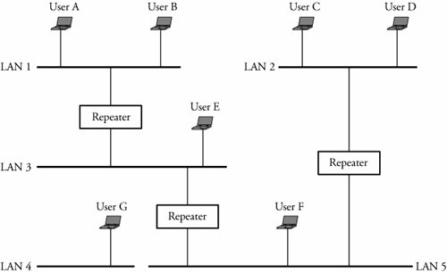 Figure 5.10 depicts a network connection using hubs. A hub is similar to a repeater but copies frames and forwards them to all connected users. As in the case of a repeater, collisions may occur if two or more users try to transmit at the same time. Hubs and repeaters have the following limitations.
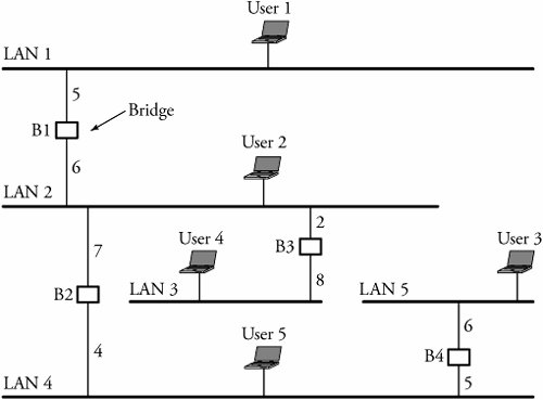
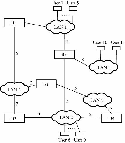
Figure 5.10. Using hubs in layer 1 BridgesClearly, using a bridge for networking Ethernet LANs can reduce the possibility of collision, as bridges split a LAN system into different collision domains. Because they can selectively retransmit the frame, bridges also offer a greater level of security than repeaters can. Bridges also facilitate communication across multiple LANs and bridges. Sometimes, a bridge that connects two LANs with nonidentical bit rates must have a buffer. A buffer in a bridge holds frames that arrive from a faster LAN directed to a slower LAN. This introduces transmission delay and has adverse effects on the network, causing the flow-control protocols to time out. Figure 5.11 shows multiple bus LANs being connected by bridges. Suppose that user 1 wants to transmit a frame to user 5. First, bridge B1 examines the destination address and determines whether the forwarded frame is to be delivered to any of the users on LAN 2. If user 3 is not the destination within its connected LANs, the frame can be either dropped or forwarded on LAN2. Making such decisions is a bridge routing capability and depends on how well the routing table of the bridge is structured. Thus, the bridge decides whether to accept or reject a frame at any time. Figure 5.11. Connecting LANs through bridges If it decides to forward a frame on LAN 2, bridge B1 also performs error detection to ensure that the frame is not corrupted. Next, the bridge checks whether LAN 2 and LAN 5 have the same frame format. If they do, the bridge forwards the frame as is. If the frame format is different, it is reformatted to match the frame format of LAN 5. Since a bridge in such scenarios is generally connected to an Ethernet LAN, the bridge has to conform to CSMA/CD while transmitting the frame. When the frame reaches bridges B2 and B3, the same procedure as the one completed in B1 takes place. As a result, B3 rejects the frame, and B2 accepts the frame. The frame is now forwarded on LAN 2. The frame ultimately reaches the destination at user 3 after passing safely over LAN 2, B3, and LAN 3. A bridge that connects two LANs, such as an Ethernet LAN and a token-ring LAN, has to reformat frames before any transmission. A frame arriving from a token-ring LAN is reformatted to match the Ethernet LAN. As the Ethernet frame format does not contain the priority field, the priority information specified by the token-ring frame is lost. In contrast, a frame arriving from an Ethernet network is assigned a default priority before transmission to the token-ring LAN. Figure 5.12 shows an example in which a LAN using bridges and hubs interconnects a token-ring LAN with several other LANs. Figure 5.12. Using bridges and hubs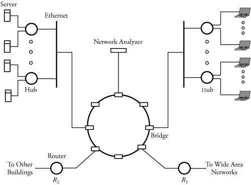 A bridge does not have a global view of its outside network but rather has knowledge only of immediate neighbors. Bridge routing is a process of deciding where to forward received frames. Bridges have this information stored in a table called the routing table . Each bridge has multiple subrouting tables for corresponding to all its existing surrounding connected LANs. The routing table consists of the destination address and the destination LAN.
In a static network, connections are fixed, so the routing table entries can be programmed into the bridge: fixed routing . In case of any changes to the network, the table entries need to be reprogrammed. This solution is not scalable for large, dynamic networks having frequent user addition and removal. Hence, such networks use an automatic update of the routing tables. In Figure 5.13, for example, if user 1 on LAN 1 sends a frame to user 5 on LAN 1, any corresponding bridge, such as B1 or B5 can figure out that both user 1 and user 5 belong to LAN 1 and forward the frame within LAN 1. Bridge B1 or B2 has the MAC addresses of both user 1 and user 5. Similarly, if user 10 is transmitting a frame to user 11, bridge B5 records the MAC addresses of users 10 and 11 and LAN 3 in its routing table. Each bridge must parse the destination address of an incoming frame in its routing table to determine the association between the destination MAC address and the MAC addresses of the devices connected to its LAN. The bridge scans the routing table to determine whether an association exists and forwards the frame if an entry is in the routing table. Figure 5.13. Bridging in local area networks Bridges that update their routing tables are called transparent bridges and are typically equipped with the IEEE 802.1d standard. These bridges act as plug-and-play devices and have the capability to build their own routing tables instantaneously. A transparent bridge also has the intelligence to learn about any change in the topology and to update its routing table. This type of bridge can dynamically build the routing table, based on the information from arriving frames. By parsing the source address of a received frame, a bridge can determine how it can access the local area network of the arriving frame. Based on this information, the bridge updates its routing table.
Spanning-Tree AlgorithmThe spanning-tree algorithm is used to overcome the problem of infinite loops in networks with bridges. A spanning tree generates a subset of bridges to be used in the network to avoid loops . The algorithm is as follows Begin Spanning-Tree Algorithm
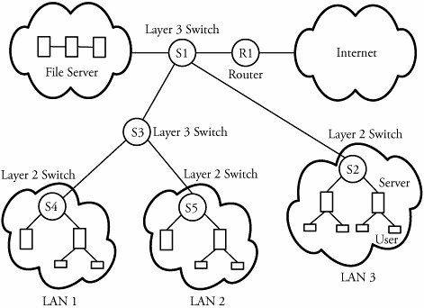
5.7.2. Layers 2 and 3 SwitchesAs the complexity of the network system grows, layer 2 devices are not adequate to meet the needs of networks. Users on LANs connected by layer 2 switches have a common MAC broadcast address. Hence, a frame with a broadcast MAC address is forwarded to all users on the network. In a large network, this is considered a large overhead and may result in network congestion. Another issue with layer 2 switches is that to avoid closed loops, there can be only one path between two users. This poses a significant limitation on the performance of large networks. The limitations are overcome by splitting the network into subnets. Routers, known as layer 3 switches, implement the switching and forwarding functions at the network layer of the protocol stack. The routers are capable of handling heavy traffic loads. Routers are also used to connect multiple subnets in LANs. Routers are sophisticated devices that permit access to multiple paths among users. A router uses software to forward packets or frames. However, the use of software significantly reduces the speed of forwarding frames. But high-speed LANs and high-performance layer 2 switches can operate on millions of frames per second, which mandates layer 3 devices to match the load. Figure 5.15 shows a typical network scenario in a large organization. The network is split up into subnets, each having a number of desktop systems connected to a layer 2 switch. A layer 3 switch acts as the backbone and connects layer 2 switches through higher-speed links. Servers are connected to either the layer 2 or the layer 3 switch. A software-based router provides the WAN connection. Figure 5.15. A network with layers 2 and 3 switches |
EAN: 2147483647
Pages: 211
- Chapter I e-Search: A Conceptual Framework of Online Consumer Behavior
- Chapter IV How Consumers Think About Interactive Aspects of Web Advertising
- Chapter XI User Satisfaction with Web Portals: An Empirical Study
- Chapter XV Customer Trust in Online Commerce
- Chapter XVIII Web Systems Design, Litigation, and Online Consumer Behavior