Section 19.3. Routing Protocols for Ad-Hoc Networks
 metric with a new sequence number (incremented) is assigned to it to ensure that the sequence number of that metric is always greater than or equal to the sequence number of that node. Figure 19.2 shows a routing table for node 2, whose neighbors are nodes 1, 3, 4, and 8. The dashed lines indicate no communications between any corresponding pair of nodes. Therefore, node 2 has no information about node 8.
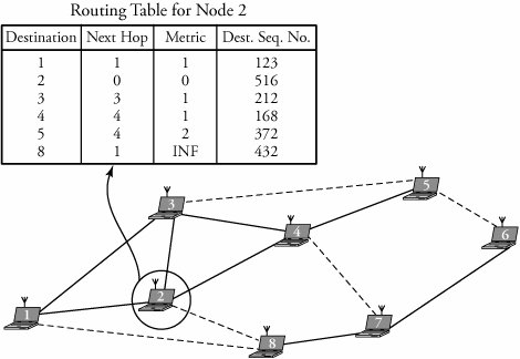
| Example. | Figure 19.4 shows an ad-hoc network with eight mobile nodes and a broken link (3-7). Node 1 wants to send a message to the destination, node 8. Node 1 looks at its routing table, finds an expired route to node 8, and then propagates route-request packets to nodes 3 and 2. Node 3 finds no route to the destination and so appends the route record 1-3 to the route-request packet and forwards it to node 4. On receiving this packet, node 7 finds a route to the destination and so stops propagating any route-request packet and instead sends a route-reply packet to the source. The same happens when a route-request packet reaches the destination node 8 with a route record 1-2-4-6. When the source, node 1, compares all the route-reply packets, it concludes that the best route is 1-2-4-6-8 and establishes this path. Figure 19.4. Summary of DSR connection setup from node 1 to node 8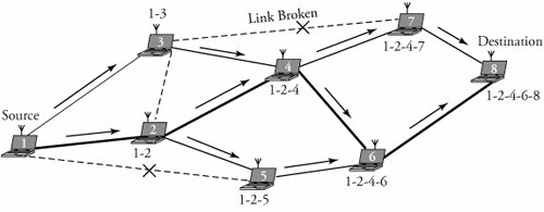 Route maintenance in this protocol is fast and simple. In case of a fatal error in the data-link layer, a route-error packet is generated from a failing node. When the route-error packet is received, the failing node is removed from its route cache, and all routes containing that node are truncated. Another route-maintenance signal is the acknowledgment packets sent to verify the correct operation of the route links. |
19.3.5. Temporally Ordered Routing Algorithm (TORA)
The Temporally Ordered Routing Algorithm (TORA) is a source-initiated routing algorithm and, thus, creates multiple routes for any source/destination pair. The advantage of multiple routes to a destination is that route discovery is not required for every alteration in the network topology. This feature conserves bandwidth usage and increases adaptability to topological changes by reducing communication overhead.
TORA is based on the following three rules:
-
Route creation/discovery
-
Route maintenance
-
Route erasure
TORA uses three types of packets: query packets for route creation, update packets for both route creation and maintenance, and clear packets for route erasure. With TORA, nodes have to maintain routing information about adjacent nodes. This loop-free protocol is distributed based on the concept of link reversal .
Every node maintains a table describing the distance and status of all connected links. When a node has no route to a desired destination, a route-creation process starts. A query packet contains the destination ID, and an update packet contains the destination ID and the distance of the node. A receiving node processes a query packet as follows
-
If the receiving node realizes that there are no further downstream links, the query packet is again broadcast. Otherwise, the node discards the query packet.
-
If the receiving node realizes that there is at least one downstream link, the node updates its routing table to the new value and broadcasts an update packet.
Once it receives the update packet, a node sets its distance greater than the neighbor from which it received the packet and then rebroadcasts it. The update is eventually received by the source. When it realizes that there is no valid route to the destination, the node adjusts its distance and generates an update packet. TORA performs efficient routing in large networks and in mildly congested networks.
19.3.6. Associative-Based Routing (ABR) Protocol
Associative-Based Routing (ABR) is an efficient on-demand, or source-initiated, routing protocol. ABR's is better than WRPs' network-change adaptation feature, to the extent that it is almost free of loops and is free of packet duplications. In ABR, the destination node decides the best route, using node associativity. ABR is ideal for small networks, as it provides fast route discovery and creates shortest paths through associativity.
In ABR, the movements of nodes are observed by other nodes in the network. Each node keeps track of associativity information by sending messages periodically, identifying itself and updating the associativity ticks for its neighbors. If the associativity ticks exceed a maximum, a node has associativity stability with its neighbors. In other words, a low number of associativity ticks shows the node's high mobility, and high associativity indicates a node's sleep mode. The associativity ticks can be reset when a node or its neighbor moves to a new location.
Each point-to-point routing in ABR is connection oriented, with all nodes participating in setting up and computing a route. In a point-to-point route, the source node or any intermediate node decides the details of routes. If the communication must be of broadcast type, the source broadcasts the packet in a connectionless routing fashion.
Route discovery is implemented when a node wants to communicate with a destination with no valid route. Route discovery starts with sending a query packet and an await-reply . The broadcast query packet has the source ID, destination ID, all intermediate nodes' IDs, sequence number, CRC , LIVE field and a TYPE field to identify the type of message. When it receives a query packet, an intermediate node looks at its routing table to see whether it is the intended destination node; otherwise, it appends its ID to the list of all intermediate IDs and rebroadcasts the packet. When it receives all copies of the query packet, the destination node chooses the best route to the source and then sends a reply packet including the best route. This way, all nodes become aware of the best route and thereby make other routes to the destination invalid.
ABR is also able to perform route reconstruction . This function is needed for partial route discovery or invalid route erasure.
19.3.7. Ad-Hoc On-Demand Distance Vector (AODV) Protocol
The Ad-Hoc On-Demand Distance Vector (AODV) routing protocol is an improvement over DSDV and is a source-initiated routing scheme capable of both unicast and multicast routing. AODV establishes a required route only when it is needed as opposed to maintaining a complete list of routes, with DSDV. AODV uses an improved version of the distance vector algorithm, explained in Chapter 7, to provide on-demand routing. AODV offers quick convergence when a network topology changes because of any node movement or link breakage . In such cases, AODV notifies all nodes so that they can invalidate the routes using the lost node or link. This protocol adapts quickly to dynamic link conditions and offers low processing, memory overhead, and network utilization. Loop-free AODV is self-starting and handles large numbers of mobile nodes. It allows mobile nodes to respond to link breakages and changes in network topology in a timely manner. The algorithm's primary features are as follows.
-
It broadcasts packets only when required.
-
It distinguishes between local connectivity management and general maintenance.
-
It disseminates information about changes in local connectivity to neighboring mobile nodes that need this information.
-
Nodes that are not part of active paths neither maintain any routing information nor participate in any periodic routing table exchanges.
-
A node does not have to find and maintain a route to another node until the two nodes communicate. Routes are maintained on all nodes on an active path. For example, all transmitting nodes maintain the route to the destination.
AODV can also form multicast trees that connect multicast group members . The trees are composed of group members and the nodes needed to connect them. This is similar to multicast protocols, explained in Chapter 15.
Routing Process
A route is active as long as data packets periodically travel from a source to a destination along that path. In other words, an active route from a source to a destination has a valid entry in a routing table. Packets can be forwarded only on active routes. Each mobile node maintains a routing table entry for a potential destination. A routing table entry contains
-
Active neighbors for a requested route
-
Next-hop address
-
Destination address
-
Number of hops to destination
-
Sequence number for the destination
-
Expiration time for the route table entry (timeout)
Each routing table entry maintains the addresses of the active neighbors so that all active source nodes can be notified when a link along the route to the destination breaks. For each valid route, the node also stores a list of precursors that may transmit packets on this route. These precursors receive notifications from the node when it detects the loss of the next-hop link.
Any route in the routing table is tagged with the destination's sequence number , an increasing number set by a counter and managed by each originating node to ensure the freshness of the reverse route to a source. The sequence number is incremented whenever the source issues a new route-request message. Each node also records information about its neighbors with bidirectional connectivity. The insertion of a sequence number guarantees that no routing loops form even when packets are delivered out of order and under high node mobility. If a new route becomes available to the requested destination, the node compares the destination sequence number of the new incoming route with the one stored in the routing table for the current route. The existing entry is updated by replacing the current entry with the incoming one if one of the following conditions exist.
-
The current sequence number in the routing table is marked invalid.
-
The new incoming sequence number is greater than the one stored in the table.
-
The sequence numbers are the same, and the new hop count is smaller than the one for the current entry.
Once the source stops sending data packets on an established connection, the routes time out and are eventually deleted from the intermediate-node routing tables. At the reverse-path entry of any routing table, a request-expiration timer purges the reverse-path routing entries from the nodes that do not lie on the route from the source to the destination. When an entry is used to transmit a packet, the timeout for the entry is reset to the current time plus the active-route timeout. The routing table also stores the routing caching time out , which is the time after which the route is considered to be invalid.
Route Discovery and Establishment
Suppose that a source node does not have information about a destination node, perhaps because it is unknown to the source node or a previously valid path to the destination expires or is marked invalid. In such cases, the source node initiates a route-discovery process to locate the destination. Route discovery is done by broadcasting a route request (RREQ) packet to neighbors, which in turn is forwarded to their neighbors until the destination node is reached. If it receives an already processed RREQ, a node discards the RREQ and does not forward it. Neighboring nodes update their information and set up backward pointers to the source node in their route tables. Each neighbor either responds to the RREQ by sending back a route-reply RREP to the source or increases the hop count and broadcasts the RREQ to its own neighbors; in this case, the process continues.
An RREQ packet contains the following information:
-
Source address
-
A unique RREQ
-
Destination address
-
Source sequence number
-
Destination sequence number
-
Hop count
-
Lifetime
When an RREQ packet arrives at an intermediate node on a route, the node first updates the route to the previous hop. The node then checks whether the available route is current and completes this check by comparing the destination sequence number in its own route entry to the destination sequence number in the RREQ packet. If the destination sequence number is greater than the one available in the intermediate node's routing table, the intermediate node must not use its recorded route to respond to the RREQ. In this case, the intermediate node rebroadcasts the RREQ to its neighboring node.
On receipt of an RREQ, an intermediate node maintains the address of each neighbor from which the first copy of the packet is received in their route tables and establishes a reverse path. Therefore, if additional copies of the same RREQ are received, they are discarded. When the RREQ reaches the destination node, it responds by sending a route reply (RREP) packet back to the neighbor from which the RREQ was first received. As the RREP is routed back, nodes along this reverse path setup forward route entries in their routing tables, which indicates the node from which the RREP came.
Any intermediate node checks whether it has received an RREQ with the same source node IP address and RREQ within at least the last path-discovery time. If such an RREQ has been received, the node drops the newly received RREQ. The reverse-route entries are maintained long enough for the RREQ packet to pass through the network and produce a reply to the sender. For the RREQ that is not dropped, the node increments the hop count and then searches for a reverse route to the source. At this point, a routing timer associated with each route times out and deletes the entry if it has not received any RREP or is not used within a specified time. The protocol uses destination sequence-numbers to ensure that links are free of loops at all times and thus avoids counting to infinity. The destination address field is incremented every time a source issues a new RREQ.
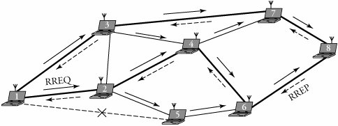
| Example. | Figure 19.5 shows the process of signals with AODV from node 1 to node 8. To establish a connection, source node 1 searches in its table for a valid route to destination node 8. In the figure, an RREQ reaches the destination for the first time through path 1-2-4-6-8. The destination then issues an RREP packet to the source. After a while, the destination receives another RREQ, this time through path 1-3-7-8. The destination evaluates this path, and finds that path 1-3-7-8 is better, and then issues a new RREP packet, telling the source to discard the other reply. Figure 19.5. AODV communication signaling from node 1 to node 8 |
As an RREP packet is propagated back to the source, involving nodes set up forward pointers to the destination. At this time, the hop-count field is incremented at each node. Thus, when the RREP packet reaches the source, the hop count represents the distance of the destination from the originator. The source node starts sending the data packets once the first RREP is received. If it receives an RREP representing a better route to the destination, the source node then updates its routing information. This means that, while transmitting, if it receives a better RREP packet containing a greater sequence number or the same sequence number with a smaller hop count, the source may update its routing information for that destination and switch over to the better path. As a result, a node ignores all less-desired RREPs received while transmitting.
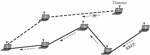
At the reverse-path entry of any routing table, a request-expiration timer purges the reverse-path routing entries from the nodes that do not lie on the route from the source to the destination. When an entry is used to transmit a packet, the timeout for the entry is reset to the current time plus the active-route timeout. The routing table also stores the routing caching timeout , which is the time after which the route is considered invalid. In Figure 19.6, a timeout has occurred. From the source node 1 to the destination node 8, two routes 1-2-4-6-8 and 1-3-7-8, are found. However, the RREP at the intermediate node 7 exceeds the time allowed to be released. In this case, route 1-3-7-8 is purged from the involving routing tables.
Figure 19.6. Occurrence of a timeout
Route Maintenance
After it knows how to establish a path, a network must maintain it. In general, each forwarding node should keep track of its continued connectivity to its active next hops. If a source node moves, it can reinitiate route discovery to find a fresh route to the destination. When a node along the route moves, its upstream neighbor identifies the move and propagates a link-failure notification message to each of its upstream neighbors. These nodes forward the link-failure notification to their neighbors, and so on, until the source node is reached. The source node may reinitiate path-discovery if a route is still desired.
When the local connectivity of a mobile node is required, each mobile node can get information about other nodes in its neighborhood by using local broadcasts known as HELLO messages. A node should use HELLO messages only if it is part of an active route. A node that does not receive a HELLO message from its neighbors along an active route sends a link-failure notification message to its upstream node on that route.
When it moves during an active session, a source node can start the route-discovery process again to find a new route to the destination node. If the destination or the intermediate node moves, a special RREP is sent to the affected source nodes. Periodic HELLO messages can normally be used to detect link failures. If a link failure occurs while the route is active, the upstream node of the breakage propagates a route-error (RERR) message. An RERR message can be either broadcast or unicast. For each node, if a link to the next hop is undetectable, the node should assume that the link is lost and take the following steps.
| 1. | Make all related existing routes invalid. |
| 2. | List all destination nodes that would potentially be affected. |
| 3. | Identify all neighboring nodes that may be affected. |
| 4. | Send an RERR message to all such neighbors. |
As shown in Figure 19.1, some next-hop nodes in a network might be unreachable. In such cases, the upstream node of the unreachable node propagates an unsolicited RREP with a fresh sequence number, and the hop count is set to infinity to all active upstream neighbors. Other nodes listen and pass on this message to their active neighbors until all nodes are notified. AODV finally terminates the unreachable node (broken associated links).
Joining a New Node to Network
A new node can join an ad-hoc network by transmitting a HELLO message containing its identity and sequence number. When a node receives a HELLO message from a neighbor, the node makes sure that it has an active route to it or, if necessary, creates one. After this update, the current node can begin using this route to forward data packets. In general, nodes in a network may learn about their neighbors when a node receives a normal broadcast message or HELLO message. If the HELLO message is not received from the next hop along an active path, the active neighbors using that next hop are sent notification of a link break.
A node receiving HELLO messages should be part of an active route in order to use them. In every predetermined interval, active nodes in a network check whether they received HELLO messages from their neighbors. If it does not receive any packets within the hello interval, a node broadcasts a HELLO message to all its neighbors. Neighbors that receive this packet update their local connectivity information. Otherwise, if it does not receive any HELLO messages for more than some predetermined time, a node should assume that the link to this neighbor failed.
EAN: 2147483647
Pages: 211