Using Materials and Lighting

So what's different now than when we were first using lights? The only major difference (other than the fact that we are using a mesh) is the lack of color in our vertex data. This is the cause of the light "failing" now.

In order for Direct3D to correctly calculate the color of a particular point on a 3D object, it must not only know the color of the light, but how that object will reflect the color of that light. In the real world if you shine a red light on a light blue surface, that surface will appear a soft purple color. You need to describe how our "surface" (our cube) reflects light.

In Direct3D, materials describe this property. You can specify how the object will reflect ambient and diffuse lighting, what the specular highlights (discussed later) will look like, and whether the object appears to emit light at all. Add the following code to your DrawBox call (before the DrawSubset call).

 Material boxMaterial = new Material(); boxMaterial.Ambient = Color.White; boxMaterial.Diffuse = Color.White; device.Material = boxMaterial; 

Here we create a new material, and set its ambient and diffuse color values to white. Using white means we will reflect all ambient and diffuse lighting that hits these objects. We then use the Material property on the device so that Direct3D knows which material to use while rendering its data.

Running the application now shows us the red cubes spinning around that we expected to see before. Modifying the ambient light color will change the color of every cube in the scene. Modifying the ambient color component of the material will change how the light is reflected off of the object. Changing the material to a color with absolutely no red in it (such as green) will cause the object to once again render black. Changing the material to a color with some red (for example, gray) will cause the object to appear a darker gray.

There are actually quite a few stock objects you can use when using mesh files. Use any of the following methods for creating these meshes (each of the stock mesh functions requires the device as the first parameter):

 mesh = Mesh.Box(device, 2.0f, 2.0f, 2.0f); 

SHOP TALK: USING MORE REALISTIC LIGHTING

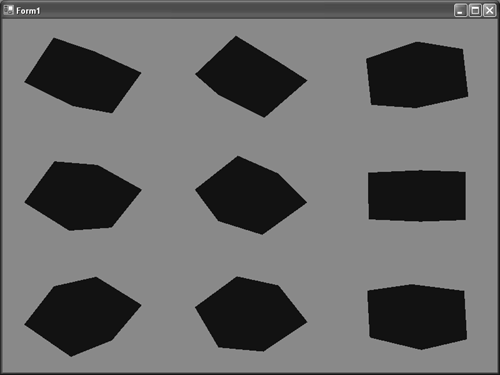
As you can tell, the cubes don't look very realistic when rendered in this way. You can't even see where the "corners" of the cube are; it just looks like a blob of red in a cube-like shape. This is due to how ambient light affects the scene. If you remember, ambient light will calculate lighting the same for every vertex in a scene, regardless of normal, or any parameter of the light. See Figure 5.1.

Figure 5.1. Ambient light with no shading.

graphics/05fig01.gif

To make a more realistic-looking cube, we will need to add a real light to our scene. Comment out the ambient light line and add the following lines below it:

 device.Lights[0].Type = LightType.Directional; device.Lights[0].Diffuse = Color.DarkBlue; device.Lights[0].Direction = new Vector3(0, -1, -1); device.Lights[0].Commit(); device.Lights[0].Enabled = true; 

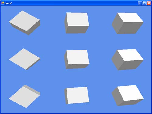
This will create a dark blue directional light pointing in the same direction the camera is facing. Running the application now will result in the cubes (now dark blue) much more realistically shaded as they spin around. You can see that the faces directly in the path of the light have the full color applied, while faces not directly in the path of the light are shaded darker (possibly even completely black). See Figure 5.2.

Figure 5.2. Cubes shaded realistically using directional lights.

graphics/05fig02.jpg

Uses a left-handed coordinate system to create a box.

Width

Specify the size of the box along the x-axis.

Height

Specify the size of the box along the y-axis.

Depth

Specify the size of the box along the z-axis.

 mesh = Mesh.Cylinder(device, 2.0f, 2.0f, 2.0f, 36, 36); 

Uses a left-handed coordinate system to create a cylinder.

Radius1

The radius of the cylinder on the negative z end. This value should be greater than or equal to 0.0f.

Radius2

The radius of the cylinder on the positive z end. This value should be greater than or equal to 0.0f.

Length

Length of the cylinder on the z-axis.

Slices

The number of slices along the main axis (larger value will add more vertices).

Stacks

The number of stacks along the main axis (larger value will add more vertices).

 mesh = Mesh.Polygon(device, 2.0f, 8); 

Uses a left-handed coordinate system to create a polygon.

Length

The length of each side of the polygon

Sides

Number of sides this polygon will have mesh = Mesh.Sphere(device, 2.0f, 36, 36);

Uses a left-handed coordinate system to create a sphere.

Radius

Radius of the created sphere. This value should be greater than or equal to 0.

Slices

The number of slices along the main axis (larger value will add more vertices)

Stacks

The number of stacks along the main axis (larger value will add more vertices)

 mesh = Mesh.Torus(device, 0.5f, 2.0f, 36, 18); 

Uses a left-handed coordinate system to create a torus.

InnerRadius

Inner radius of the created torus. This value should be greater than or equal to 0.

OutterRadius

Inner radius of the created torus. This value should be greater than or equal to 0.

Sides

Number of sides in a cross section of the torus. This value must be greater than or equal to three.

Rings

Number of rings in a cross section of the torus. This value must be greater than or equal to three.

 mesh = Mesh.Teapot(device); 

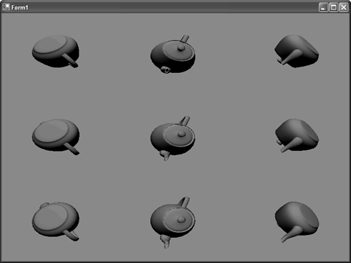
Uses a left-handed coordinate system to create a teapot (yes a teapot). See Figure 5.3.

Figure 5.3. The intrinsic teapot mesh.

graphics/05fig03.gif

Each of these methods also has a second overload that can return adjacency information. Adjacency information is returned as three integers per face that specify the three neighbors of each face in the mesh.


Managed DirectX 9 Graphics and Game Programming, Kick Start
Managed DirectX 9 Kick Start: Graphics and Game Programming
ISBN: B003D7JUW6
EAN: N/A
Year: 2002
Pages: 180
Authors: Tom Miller

flylib.com © 2008-2017.
If you may any questions please contact us: flylib@qtcs.net