10.1 Media Access Control Protocol
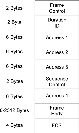
| The wireless Ethernet MAC defined in the 802.11 standards is common for all different implementations of RF transmission methods including FHSS, DSS, HRDSS, and OFDM, as well as for the infrared implementation. The main CDMA/CA protocol is defined as a distributed coordination function (DCF) and also sometimes called the frame exchange protocol. This protocol defines different MAC frames and procedures for exchanging frames. These MAC frames are to be encapsulated with different preambles and packet headers in accordance with particular transmission methods. A polling system using a point coordinator is also defined as the point coordination function (PCF) for timing-sensitive applications. PCF is built upon DCF, and they can simultaneously share the same transmission medium. To fight against the possibility of eavesdropping, a WEP is also defined using encryption with shared keys distributed through secure channels other than over the air. 10.1.1 Frame FormatFigure 10.1 shows the general format of a wireless Ethernet MAC frame as defined by the IEEE 802.11 standards. A particular version of wireless Ethernet packet is formed by encapsulating the MAC frame with a physical layer dependent preamble and header. Therefore, no preamble is defined for the wireless Ethernet frame. Figure 10.1. 802.11 MAC Frame Format
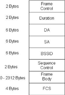
The Frame Control field consists of the following subfields: Protocol Version, Type, Subtype, To DS (Distribution System), From DS, More Fragments, Retry, Power Management, More Data, WEP, and Order. A DS is used to interconnect a set of basic service sets (BSSs) and LANs to create an extended service set (ESS). The Protocol Version field has 2 zero bits for this standard. The Type field also has 2 bits, and the Subtype field has 4 bits. The Type and Subtype fields together identify the function of the frame. The To DS field has only 1 bit and is set to 1 in data type frames destined for the DS. The From DS field has 1 bit and is set to 1 in data-type frames exiting the DS. The More Fragments field has 1 bit and is set to 1 in all frames that have another fragment to follow. The Retry field has 1 bit and is set to 1 in any frame that is a retransmission of an earlier frame. The Power Management field has 1 bit and is used to indicate the power management mode of a transceiver. A value of 1 indicates that the transceiver will be in power-save mode. The More Data field has 1 bit and is used to indicate to a transceiver in power-save mode that more frames are buffered at the access point. A value of 1 indicates that at least one additional buffered frame is present for the same transceiver. The WEP field has 1 bit. It is set to 1 if the Frame Body field contains information that has been processed by the WEP algorithm. The Order field has 1 bit and is set to 1 in a data-type frame. The Duration/ID field has 16 bits, which identify the transceiver for the power save poll subtype of the control type frame or the duration value for other types of frames. Four address fields follow the duration field in the MAC frame. These fields are used to indicate the basic service set identifier (BSSID), source address (SA), destination address (DA), transmitting transceiver address (TA), and receiving transceiver address (RA). The location of a particular type of address among these address fields depends on the specific frame type. The Sequence Control field has 16 bits and consists of two subfields, the Sequence Number and the Fragment Number. The Sequence Number field is a 12-bit field indicating the sequence number of a MAC frame. The Fragment Number field is a 4-bit field indicating the number of each fragment of MAC frame. The fragment number is set to zero in the first or only fragment and is incremented by one for each successive fragment. The Frame Body can have 0 to 2312 bytes. The FCS field contains a 32-bit CRC. The FCS is calculated over all the fields of the MAC header and the Frame Body field using the same generator polynomial of degree 32 as that of Ethernet defined by the 802.3 standards: Equation 10.1
The wireless Ethernet FCS is the 1's complement of the exclusive OR of the remainder of xk(x31 + x30 + x29 + … + x2 + x + 1) divided by G(x) and the remainder of the message polynomial multiplied by x32 and then divided by G(x), where k is the number of message bits. As a typical implementation, at the transmitter, the initial remainder of the division is preset to all 1's and is then modified by division of the message polynomial by the generator polynomial G(x). The 1's complement of this remainder is transmitted, with the highest-order bit first, as the FCS field. At the receiver, the initial remainder is preset to all 1's and the serial incoming bits of the message and FCS, when divided by G(x), results in a unique nonzero polynomial of Equation 10.2
in the absence of any transmission error. There are three frame types control, data, and management and six control frame subtypes Request To Send (RTS), Clear To Send (CTS), Acknowledgment (ACK), Power Save-Poll (PS-Poll), contention-free-end (CF-End), and contention-free-end acknowledge (CF-End+CF-ACK). The RTS frame format is as defined in Figure 10.2. The duration value is the time (in microseconds) required to transmit the pending packet. The RA is the intended receiving transceiver address. The TA is the transmitting transceiver address. Figure 10.2. RTS Frame Format
The CTS frame format is as defined in Figure 10.3. The duration value is the value obtained from the Duration field of the immediately previous RTS frame minus the time required to transmit the CTS frame. The RA is copied from the TA field of the immediately previous RTS frame. Figure 10.3. CTS and ACK Frame Format
The ACK frame format is as that of CTS. If the More Fragment bit is set to 0 in the Frame Control field of the immediately previous directed frame, the duration value is set to 0. If the More Fragment bit is set to 1, the duration value is the value obtained from the Duration field of the immediately previous frame, minus the time required to transmit the ACK frame.The RA of the ACK frame is copied from the Address 2 field of the immediately previous directed frame. The PS-Poll frame is as defined in Figure 10.4. The AID is the value assigned to the transmitting transceiver by the access point. The BSSID is the address of the access point transceiver. The TA is the address of the transmitting transceiver. Figure 10.4. PS-Poll Frame Format
The CF-End frame format is as defined in Figure 10.5. The Duration field is set to 0. The RA is the broadcast group address. The BSSID is the address of the access point transceiver. Figure 10.5. CF-End Frame Format
The CF-End+CF-ACK frame format is the same as that of CF-End. The Duration field is set to 0. The RA is the broadcast group address. The BSSID is the address of access point transceiver. The data frame has the general MAC frame format as defined in Figure 10.1. The content of the address fields in the data frame is dependent upon the values of the To DS and From DS bits as shown in Table 10.1. Where the content of a field is shown as not applicable (N/A), the field is omitted. The frame format for a Management frame is as defined in Figure 10.6. Eleven management frame subtypes share the same frame format but have different sizes of frame bodies: Beacon, IBSS Announcement Traffic Indication Message (ATIM), Disassociation, Association Request, Association Response, Reassociation Request, Reassociation Response, Probe Request, Probe Response, Authentication, and Deauthentication. Figure 10.6. Management Frame Format
10.1.2 Carrier Sense Multiple Access with Collision AvoidanceThe CSMA/CA MAC protocol is similar to that of CSMA/CD in that both use the basic carrier sensing mechanism to share a transmission medium among many transceivers. Some additional procedures are adopted by the CSMA/CA protocol owing to the fact that the detection of a collision is not guaranteed for the RF transmission medium. This can happen when two transmitters that are far apart compete for the attention of a receiver in the middle. Under the CSMA/CA protocol, a short acknowledgment packet is expected from the intended receiver back to the transmitter after every reception of an original long packet after the correct FCS is checked. To guarantee the reception of the short packet, an acknowledgment transceiver can respond immediately under the definition of the short interframe space (SIFS), while other transceivers must wait through a priority interframe space (PIFS) or a distributed interframe space (DIFS) time window. To avoid potential collision of long packets, which is sometimes called the hidden node problem, an RTS short packet is sent first and the intended receiver responds with a CTS short packet within the SIFS prior to the target long packet transmission. The CTS short packet enables transceivers that do not receive the RTS directly also to be aware of pending transmission. Because of this unique RF transmission environment, the virtual carrier sensing is also implemented via the detection of pending transmission duration from the CTS packet by other transceivers for CSMA/CA. Transceivers that detect pending transmissions set their Network Allocation Vectors (NAV) accordingly, and no transmissions are attempted until the NAV duration has expired. The 802.11 implementation of CSMA/CA MAC protocol is called the distributed coordinate function in the standards and is also known as the frame exchange protocol. Figure 10.7 shows the timing relationship between different interframe spaces. Figure 10.7. Interframe Spaces
The SIFS is used for an ACK frame, a CTS frame, and the second or subsequent packets of a fragment burst. The SIFS timing consists of transmission, receiver detection, MAC decision, and turn-around time delays. The PIFS is used only by transceivers operating under the point coordinated function (PCF), which will be discussed in the next section, for timing-sensitive applications to gain priority access to the medium at the start of the CFP. The duration of a PIFS is the duration of SIFS plus one slot time of 50 µs. Transceivers use the DIFS operating under the DCF to transmit data frames and management frames. The duration of a DIFS is the duration of PIFS plus one slot time of 50 µs. The DCF uses the EIFS whenever the transceiver has indicated to the MAC that a frame transmission was begun and did not result in the correct reception of a complete MAC frame with a correct FCS value. The duration of an EIFS is the duration of a DIFS plus another slot time of 50 µs. 10.1.3 Contention-free Frame TransferThe PCF provides contention-free transmission periods for timing-sensitive applications within the otherwise contention-oriented CSMA/CA protocol. The PCF is a polling system controlled by a point coordinator (PC). The PC is usually implemented in an access point. The capability for an access point to become a PC is optional. Transceivers, willing to be a part of a contention-free transmission mechanism, send association request packets indicating their pollable capabilities to a PC. The PC keeps a polling list and polls transceivers according to their AIDs in an ascending order as soon as a contention-free period (CFP) is established. A PC establishes an initial CFP by sending a beacon packet right after the PIFS period from the previous contention-oriented packet. Subsequent CFPs are enabled by periodic beacon packets from the PC. Each CFP is maintained by the NAV in the beacon packet and by SIFS periods between packets traveling back and forth among the PC and associated transceivers. A CFP is terminated by a CF-End packet from the PC. Competing contention-oriented transceivers reset their NAVs after the CF-End packet is detected. The operation of a CFP is illustrated in Figure 10.8. Figure 10.8. PCF Frame Transfer
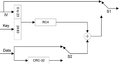
A contention period must be long enough to contain at least one maximum length frame and its acknowledgment follows each periodic CFP. Because the PC might compete for the medium, the beginning of the CFP may be delayed from its ideal start time. The traffic in the CFP consists of packets sent from the PC to transceivers, followed by the acknowledgment from them. The PC sends a CF-Poll packet to those transceivers on the polling list. If the transceiver polled has traffic to send, it may transmit one packet for each CF-Poll received. If the transceiver does not have traffic to send, it does not respond to the poll. To make the use of the medium more efficient during the CFP, it is possible to piggyback both the acknowledgment and the CF-Poll onto data packets. During the CFP, the PC ensures that the interval between packets on the medium is no longer than PIFS. The PC sends a packet to a transceiver and expects the responding packet, either an acknowledgment or a data packet, in response to a CF-Poll within an SIFS interval. If the response is not received before that SIFS interval expires, the PC transmits its next packet before a PIFS interval expires after the previous transmission. This will continue until the CFP is concluded. 10.1.4 Authentication and EncryptionThe 802.11 wireless Ethernet protocol allows either open system or shared key authentication. Under the open system authentication, a transceiver sends a management packet requesting open system authentication to another transceiver that returns a management packet to acknowledge the completion of mutual authentication. The initiation of a shared key authentication procedure can be completed by exchanging four management packets between a pair of transceivers. As soon as the shared key authentication is confirmed, transceivers encrypt the frame body part of each packet using the WEP mechanism. Because WEP relies on the knowledge of a secret key that is distributed by means other than over the open air, it should provide privacy for the wireless LAN that is equivalent to that provided by a wired LAN. The encryption structure for the shared key authentication is illustrated in Figure 10.9. Figure 10.9. WEP Encryption Structure
This WEP structure consists mainly of the RC4 encryption and CRC-32 algorithms, the exclusive OR operation between the pseudo-random sequence generated from the encryption process and the data and frame check combined sequence. This RC4 algorithm starts with a 64-bit key consisting of a 24-bit initialization vector (IV) and a 40-bit secret key. A 128-bit secret key has also been used recently for better protection. IV is attached at the beginning of every encrypted frame body as indicated by the use of the S1 switch and can be different from packet to packet. The frame check sequence, after being exclusive ORed with the pseudo-random sequence, is called the integrity check vector (ICV) and is attached at the end of each encrypted frame body as indicated by the use of the S2 switch. This WEP encryption structure produces a frame body in a format as shown in Figure 10.10. The 2-bit ID can be used to identify one of four agreed-upon secret keys. Figure 10.10. WEP Frame Body Format
The decryption involves similar operations in a slightly different structure as illustrated in Figure 10.11. The 24-bit IV is first taken from the received frame body as indicated by the use of the S1 switch. The RC4 algorithm uses the IV combined with the agreed-upon key to reproduce the same pseudo-random sequence. The data sequence is recovered after the exclusive OR operation. The correctness of the frame check sequence is verified at the end of each packet as indicated by the use of the S2 switch. Figure 10.11. WEP Decryption Structure
The RC4 encryption algorithm was developed by Ron Rivest of RSA Data Security, Inc. (RSADSI), now a part of Network Associates Inc., during 1987. RC4 is a symmetric stream cipher, which uses the same key and algorithm for both encryption and decryption and supports a variable length key of up to 256 bytes. RC4 used to be a trade secret of RSADSI, but some anonymous person distributed a version of the source code, which can produce compatible encrypted messages, on the Internet during September 1994. The name RC4 might still be a trademark and some other versions of compatible codes use different names, such as ARC4. The pseudo-random sequence of RC4 is based on an array of size 256 filled with numbers from 0 to 255 in an order determined according to the key [1]. Specifically, the array is created according to following steps, which are illustrated with MATLAB commands.
The MATLAB implementation of WEP encryption with a 64-bit key that correlates to this procedure is included at the end of this chapter. |
EAN: 2147483647
Pages: 97


