4.1 In-House Electrical Wiring Cable
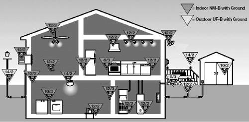
4.1.1 Electrical Wiring TypeThe Romex brand from General Cable [1] has been used for many residential electrical wirings. Within the Romex brand, NM-B type has been used for indoor branch wiring, and UF-B type, for outdoor use such as the cable to a post light. SE-U or USE-2 can be used as feeder cable for the service entrance. Both NM-B and UF-B cables are constructed with individual THHN cables of class B solid or strands of bare annealed copper conductors with an overall PVC jacket. THHN is derived from the specification of Thermoplastic insulation (PVC), High Heat resistance, and Nylon jacket. The THHN cable has a 90°C rating and is recommended for use at dry or damp locations. NM-B stands for Non-Metallic sheathed cable with class B THHN individual conductors. Similarly UF-B stands for Underground Feeder cable with class B THHN individual conductors. SE-U stands for Service Entrance Unarmored. An SE-U cable is constructed with individual THHN or individual XHHW conductors with an overall PVC jacket. XHHW is derived from the specification of XLPE (Cross-linked polyethylene) insulation, High Heat resistance, for wet and dry locations. USE-2 stands for Underground Service Entrance. The USE-2 cable is XLPE insulated and designed for direct burial application. Table 4.1 shows AWG, conductor diameter, external dimension, and ampacities of NM-B and UF-B cables for a few popular home installation choices. These external dimensions are for cables that have a copper ground. Two-conductor cables are for normal usage, while the three-conductor cables can be used for providing two phases of electricity for a combined 240 V to supply an oven or a dryer. A three-conductor cable is also useful for connecting three-way switches. These ampacities are defined by the National Electric Code [2]. The general guidelines are illustrated by Figure 4.1. Figure 4.1. General Cable Usage
Table 4.2 shows AWG, conductor diameter, external dimension, and ampacities of SE-U and USE-2 cables for a few popular home installation choices. A ground wire is not required when connecting from the service drop to the meter and from the meter to the main breaker. A three-conductor SE-U cable can be used for these connections while two two-conductor cables can be used if each phase is connected individually. Multiple USE-2 cables are required because each cable can have only one conductor.
A 100 ampacity might fit the usage of a small home, while the 175 ampacity could be required for a large home. Two ampacity estimation examples follow [3]. The first example is for a small home with a living area of 800 square feet, a 5-kilowatt wall-mount oven, a 6-kilowatt cooking unit, and a 15-ampere air conditioner. Besides these heavy-duty applinces, the lighting load is estimated at 3 watts per square feet (W/ft2). We also give 3 kilowatts (kW) for small kitchen appliances and 1.5 kW for the laundry room. The breakdown of ampacities is listed in Table 4.3. For the combined lighting, appliance, and laundry usage, we can rate the first 3000 W as 100% and the remaining watts at 35% because they are not likely to be in use at the same time. Therefore, the total wattage for lighting, appliances, and laundry is reduced to 4365 W and the effective total wattage is 18,965 W. The ampacity requirement for the household is derived by dividing the effective total wattage by 240 V because 120-V supplies are parts of the two-phase 240-V supply. This example shows that the AWG 2 cables can be used to supply electricity to a small home. The second example is for a large home with a living area of 3800 square feet, a 12-kW electrical range; a 1-kW, 120-V garbage disposal; a 10-kW, 240-V strip heater; a 6-kW, 240-V hot water heater; two 28-ampere, 240-V air conditioners, and four 1/2-horsepower, 120-V blow motors. The lighting load is also estimated at 3 W/ft2. We still give 3 kW for small kitchen appliances and 1.5 kW for the laundry room. The breakdown of ampacities is listed in Table 4.4. Again for the combined lighting, appliance, and laundry usage, we can rate the first 3000 W as 100% and the remaining watts at 35%. Therefore, the total wattage for lighting, appliances, and laundry is reduced to 7515 W. Because the heater and air conditioner will not operate at the same time and the air conditioner takes more electricity, only the ampacity of the air conditioner is considered in the estimation. For the combined disposal, range, and water heater, we can rate the first 10,000 W at 100% and the remaining watts at 40%. Therefore, the total wattage for disposal, range, and water heater is reduced to 13,600 W, and the effective total wattage is (7,515 + 13,600 + 4,704 + 13,440) = 39,259. The ampacity requirement for the household is 163.58 amperes. This example shows that the AWG 3/0 cables can be used to supply electricity to a large home.
4.1.2 Ideal Electrical Cable Transmission CharacteristicsTo carry 120 V of electricity, two insulated conductors as well as a ground wire are required. These individual conductors and the ground wire are usually enclosed in a PVC sheath to form an easy-to-handle electrical wiring cable as shown in Figure 4.2. These two conductor cables are used most often in a residential environment. Transmission characteristics of electrical cables can be estimated based on its typical parallel construction [1]. Figure 4.2. Two-Conductor with Ground NM-B Cable Configuration
Detailed dimension of a two-conductor AWG 12 cable with ground is shown in Figure 4.3. Ideal primary parameters for this parallel constructed electrical cable can be estimated as follows assuming the effect of the ground conductor can be neglected. The series resistance R can be expressed by the following expression [4]. Equation 4.1
Figure 4.3. 2 Conductor Cable Section Dimension
where r is the conductor radius in meters. The series inductance L can be expressed by Equation 4.2
where D is the distance between centers of two conductors. The shunt capacitance C can be expressed by Equation 4.3
We have assumed that the shunt conductance G can be neglected. These primary parameters can be converted to a mile basis by multiplying by 1.609 kilometers per mile (km/mi). The characteristic impedance of this parallel constructed cable is expressed by the following expression. Equation 4.4
For e/e0 Equation 4.5
Equation 4.6
Equation 4.7
Equation 4.8
A DC resistance is also included in the above expression for better accuracy. Based on these primary parameters, the insertion loss of a 100-ft 12 AWG NM-B cable is calculated and plotted in Figure 4.4. Figure 4.4. Insertion Loss of a 1000-f 12 AWG Cable
The insertion loss of an electrical wiring cable can also be approximated by using Equation 4.9
where d is measured in feet. We know that a = 5.8 x 10 8, and b = 1.5 x 10 5 for this 12 AWG electrical wiring cable. This approximation is also plotted and is virtually the same as that derived from primary parameters in Figure 4.4. 4.1.3 Crosstalk CharacteristicsTo carry two phases of 120-V electricity for heavy-duty appliances, three insulated conductors as well as a ground wire are required. These individual conductors and the ground wire can be enclosed either in a flat/parallel sheath as shown in Figure 4.5 or in a round one. These three-conductor cables provide crosstalk coupling necessary for transmission between two different phases of the in-house electrical wiring. Crosstalk characteristics of a three-conductor electrical cable can also be estimated based on its physical dimension parallel or round. Figure 4.5. Three-Conductor with Ground UF-B Cable Configuration
Dimensions of three-conductor AWG 12 cables with ground are shown in Figures 4.6 and 4.7 for parallel and round constructions, respectively. Figure 4.6. Three-Conductor with Ground UF-B Cable Section
Figure 4.7. Three-Conductor with Ground NM-B Cable Section
In the twisted pair telephone cable study, crosstalk was analyzed based on capacitance unbalances of four conductors among two pairs [5]. For this electrical wiring case, crosstalk between these two phases of electrical supply can also be analyzed by examining shunt capacitances among these three conductors. The effect of crosstalk can be better analyzed by using the concept of three two-port networks as shown in Figure 4.8. ZH1 is the input impedance between the first phase and the neutral conductors. ZH2 is the input impedance between the second phase and the neutral conductors. ZHH is the input impedance between two conductors of different phases. TP1 consists of the ZH1 as a shunt impedance. TP2 consists of ZHH as a series impedance. TP3 consists of ZH2 as a shunt impedance. Figure 4.8. Crosstalk Analysis Based on Two-port Networks
Primary parameters are estimated between a hot phase and a neutral conductor based on a 12 AWG round construction cable, which is illustrated in Figure 4.7. For e/e0 Equation 4.10
Equation 4.11
Equation 4.12
Primary parameters are estimated between two hot phase conductors also for the 12 AWG round cable. For e/e0 Equation 4.13
Equation 4.14
Equation 4.15
The following expressions are used to calculate the crosstalk model. The characteristic impedance of a twisted pair cable is related to primary parameters according to Equation 4.16
The propagation constant is calculated using Equation 4.17
ABCD Parameters for each two-port network is calculated using Equation 4.18
Equation 4.19
Equation 4.20
The open-ended impedance is calculated using Equation 4.21
ABCD matrices for TP1, TP2, and TP3 follow: Equation 4.22
Equation 4.23
Equation 4.24
The ABCD matrix for the crosstalk is then Equation 4.25
For, ZH1 = ZH2 = ZH, we have Equation 4.26
Using ABCD parameters in MCrossTalk, the insertion loss is then calculated using Equation 4.27
For, Zs(f) = Zt(f) = Z, we have Equation 4.28
By replacing with values of ABCD, we have Equation 4.29
The insertion loss of the crosstalk model for a three-conductor 100-ft 12 AWG electrical cable with 200-ohm resistive terminations at the far end Z = 100and is shown in Figure 4.9. Figure 4.9. Insertion Loss of the Crosstalk Between Two Phases
|
 1,
1, 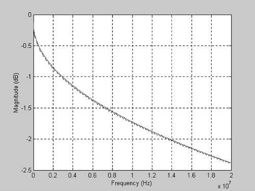
EAN: 2147483647
Pages: 97