Scalability
Introduction
Figure A.4 illustrates two different dimensions of site scalability. The first dimension, the horizontal axis, represents scaling in terms of the number of unique clients that access the site on a typical day. As the number of unique clients goes up so must the number of systems configured to support the growing client base. Typically, the content on the site required to support the client base must scale up as well.
The second dimension, the vertical axis, represents a measure of the business complexity of the site. We have identified three major categories. There are, of course, many variations in between. The categories typically build on each other with each category subsuming the functions of the category below. The lowest category and the simplest in terms of business logic complexity is the content provider category. The next category has transactions in addition to content but with much of the business processing done offline. While the top category has both content and transactions, much of the business processing logic is fully integrated with the online processing.
As sites move from left to right and bottom to top in the figure, the operational and application deployment challenges of the site increase significantly.
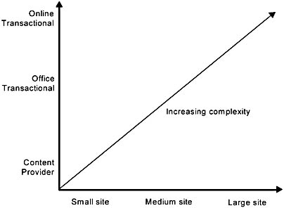
Figure A.4 Scaling dimensions
In the rest of this section, we consider scalability in the context of Figure A.4. First, we look at scaling the number of unique clients and content and then increasing the business complexity.
Scaling Clients and Content
The two illustrations that follow, Figures A.5 and A.6, show how the number of front-end systems to serve the growing client base increases, as well as how to increase the number of partitioned data stores to scale the online content.
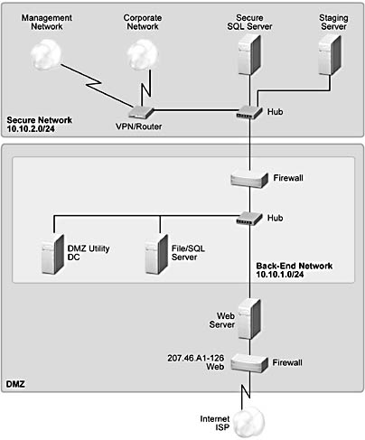
Figure A.5 A small site
The preceding figure represents a basic site with one IIS Web server, one file or SQL Server, and one utility server in the DMZ with connections to a secure SQL Server or file server and a secure staging server. The following figure represents how a small site such as the one illustrated in Figure A.5 could be scaled up to support more clients and more content.
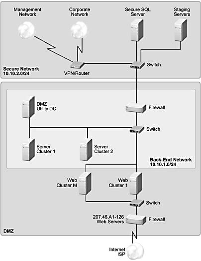
Figure A.6 A scaled-up site
At the front end, the number of IIS Web servers and the number of Web clusters of these servers are increased and the load is balanced across them using NLBS. In the back end, the number of file and SQL Server clusters is increased, and therefore logic needs to be included in the front-end Web servers to route the data requests to the correct back-end partition of the data. We describe these two techniques next.
Scaling the Front-End Systems
Increasing the number of cloned IIS Web servers, grouping them into Web clusters, and using a load-balancing system are the principal techniques for increasing the number of unique clients supported. Note, however, this involves important application state considerations, which we discuss later.
In addition to increasing the number of IIS Web servers, it is also important to optimize the Web application code that is executed in the Web servers. (This is beyond the scope of this document.)
Web front-end load balancing for scalability
Load balancing presents a single service name to clients in the form of a virtual IP address and then distributes the clients across a set of servers that implement the service.
There are three principal techniques for service load balancing:
- Round Robin DNS (RRDNS).
- Intelligent IP load balancing with a dedicated third-party outboard box.
- Intelligent IP load balancing within the servers, using NLBS in Windows 2000.
RRDNS is a method of configuring the Domain Name Servers (DNS) so that DNS lookups of a host name are sequentially distributed across a set of IP addresses, each of which can offer the same service. This gives a basic form of load balancing. The advantages to this method are: it is free, simple to implement, and requires no server changes. The disadvantages are: there is no feedback mechanism about the load or availability of individual servers, and no fast way to remove a server from the set of available servers due to the propagation delays of DNS changes resulting in requests continuing to be sent to failed servers.
With server-based load balancing, a set of servers is grouped into an NLBS cluster and the load balancing is done by having each server in the cluster decide whether to process a request based on its source IP address. When a server in the cluster fails, the remaining members of the cluster regroup and the partitioning of the source IP address ranges is adjusted. The advantages of NLBS are its low cost (NLBS is part of the Windows 2000 operating system), no special purpose hardware or changes to the network infrastructure are required, and there is no single point of failure. The current limitations are that the servers do not dynamically adjust to load and the regrouping is based on server failure, not application failure (although, third-party tools such as NetIQ and Microsoft HTTPMon can be used to alleviate these limitations).
Combining RRDNS and NLBS results in a very scalable and available configuration. All of the nodes in an NLBS cluster must be on the same LAN subnet and all respond to the same IP address. It is possible to configure multiple NLBS clusters on different subnets and to configure DNS to sequentially distribute requests across the multiple NBLS clusters. This increases the scalability of NLBS and avoids the disadvantages of RRDNS, as there are multiple machines available to respond to each request sent to each NLBS cluster. Figure A.7 illustrates this type of cluster.
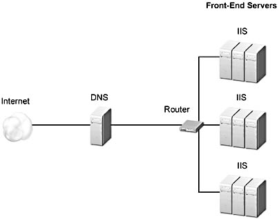
Figure A.7 RRDNS & NLBS: three separate LAN segments, one domain name
Application state considerations
To mask the failure of a server from the client, do not store application client state in an IIS Web server. Client requests cannot be dynamically load balanced. It is preferable to store client state in a data store and retrieve it if necessary on each client request based on either URL encoded data or a client cookie. A client-cached cookie is also a very effective way to scale by storing per-client information in each client's system, passing the information to the Web server on each client request and using that data to personalize content or take some other client-specific actions. RFC 2109 ("HTTP State Management Mechanism," available at www.ietf.org/rfc/rfc2109.txt) describes the HTTP cookie protocol.
However, some applications and some protocols require a persistent client-to-server connection. Using Secure Sockets Layer (SSL) to send encrypted data and authenticate the server is a prime example. Most IP load-balancing products support a mechanism that allows applications or protocols to maintain connections to the same server so that they function correctly, although without failure transparency.
Scaling the Back-End Systems
Adding more memory and more processors to a multiprocessor system can scale back-end systems. The Windows 2000 Advanced Server operating system has support for up to 8 CPUs and 8 gigabytes of memory. However, at some point that is no longer possible, or it becomes undesirable to have so much data dependent on the availability of a single system. At that point, it is necessary to scale the back-end systems by partitioning the data they serve or the logical services they provide. We call this partitioning. Unlike cloning, which is used to scale the front-end systems (where the hardware, software, and data are replicated), partitioning replicates the hardware and software but the data is divided among the nodes. Requests for a particular data object then need to be routed to the correct partition where that data is stored. This data-dependent routing needs to be implemented by application software running in the Web servers. This data-dependent routing layer can be thought of as stateful load balancing as opposed to the stateless load balancing used to scale work across the cloned front-end systems. Software also needs to be developed to manage the splitting and merging of partitions so that the load can be evenly spread across all of the partitions, thus avoiding any single partition becoming a hot spot.
The responsibility, however, is normally on the application architect to partition data into business objects that will be distributed evenly across an increasing number of servers as the size of the data and the workload increases. Fortunately, many site services are relatively easy to partition by object, as discussed earlier. However, the selection of the granularity of the objects to partition is difficult to change after site deployment, making it an extremely important upfront design decision.
Another method of scaling is to partition the services provided in the back-end systems into functionally specialized systems that offer services to their clients. This is often called an n-tier model. We discuss this in more detail in the section on scaling business complexity that follows.
Scaling the Network Infrastructure
The need for additional systems and increased security grows as more business processes are automated and either added to, or incorporated into, the existing system infrastructure. To support this increased demand, increase the bandwidth of links, upgrade hubs to switches, and install additional networks (for example, a dedicated management network to relieve the load on the back-end network).
Scaling Business Complexity
The following diagrams illustrate that as the number of business processes integrated into the system increases, and the online nature of the business processes increase, the need for security and the number of systems grows. Maximum system capacity—whether the system design can grow smoothly and quickly with business growth—is usually the primary concern of any site.
The three models of site business complexity are: Content Provider, Offline Transactional, and Online Transactional.
Content Provider. In this model, no transactional access to internal systems is required. All Web services and content servers come from within the DMZ. All content is assembled on the staging server and then pushed, using replication, to the DMZ servers. This model is scaled, as described in the previous section, by adding Web clusters, adding clones to Web clusters, and adding back-end clustered servers. Figure A.8 shows a typical content provider topology.
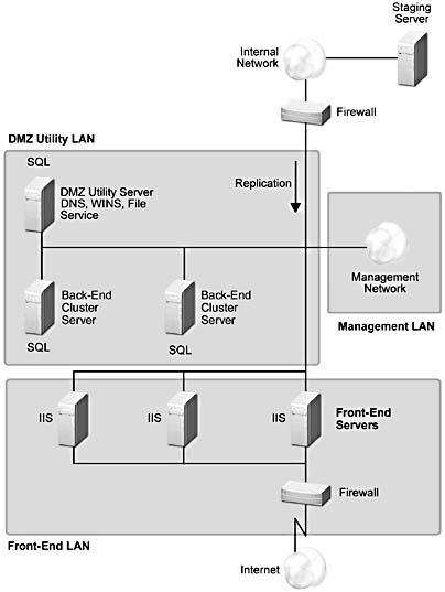
Figure A.8 Content Provider model
Offline Transactional. This model, shown in Figure A.9, is similar to the Content Provider model, but adds offline transactional access to existing business applications on the internal network. As with the Content Provider model, replication is used to update DMZ server content from the staging server. To support offline (non-real time) transactions, asynchronous transfer of transaction data from the DMZ to the internal network is required. Microsoft Message Queue (MSMQ) service can be used to reliably deliver these offline transactions. In order to support legacy delivery channels, application systems and databases are implemented on the internal network. The device labeled "other delivery channels" represents traditional presentation devices, such as client workstations, Interactive Voice Response Units (IVRUs), or specialized input devices such as point-of-sale terminals or ATMs. This model has increasing complexity as it scales the number of interactions with back-end servers in the internal network behind the inner firewall. MSMQ is useful for this type of interaction, as it supports asynchronous communications as well as guaranteed delivery of messages. Batching requests together is also another successful technique for amortizing the costs of sending messages to the internal network.
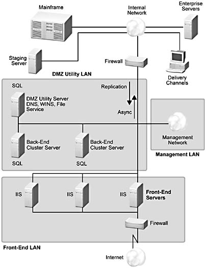
Figure A.9 Offline Transactional model
Online Transactional. In this model, Web browsers have true online access to traditional applications that are resident on the internal network. Business application functionality is implemented on the internal network, which typically supports multiple delivery channels. Transactional communication from the DMZ to the internal network is achieved using standard synchronous communication mechanisms. The requirement to integrate with online business applications while the client is connected increases the complexity of this model considerably. This model has the most complexity, and scaling it is challenging because the interactions with the internal systems have to operate synchronously, or at least while the client is interacting with the online service. These types of interactions need to be carefully designed, and the number of them minimized. A typical scenario is the electronic shopping basket that's provided for online customers. The internal, back-end systems are not accessed until a customer order is submitted for final purchase processing. Figure A.10 shows the topology for this type of transactional system.
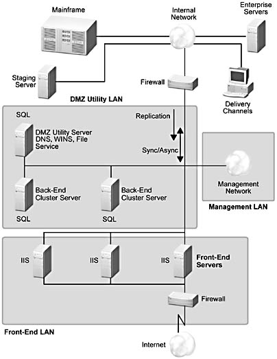
Figure A.10 Online Transactional model
EAN: N/A
Pages: 183