Lesson 1: Defining the Solution with the Microsoft Solutions Framework
Developing large, complex software projects is risky. Statistics on large information technology (IT) projects show that a significant number of software projects fail. Some of the reasons for project failure include the following:
- Constantly changing requirements
- Volatile or incomplete specifications
- Poor quality coding
- A scope that is too large
- Inadequate staffing
- Poor process
- Unclear goals
To address the problems of software development, Microsoft Consulting Services developed the Microsoft Solutions Framework (MSF). MSF is based on best practices from within Microsoft product groups, technology partners, and corporate customers. Consider using the framework to benefit your own development efforts and applying the MSF concepts as you plan a multi-developer project.
This lesson explains the features of MSF and how they relate to implementing Visual C++ applications.
After this lesson, you will be able to:Estimated lesson time: 30 minutes
- Describe the elements of MSF.
- Explain the role of MSF in the design and development process.
Overview of MSF
MSF is a collection of models, principles, and practices that helps organizations become more effective in their creation and use of technology to solve their business problems. MSF helps by providing measurable progress and adaptable guidance that is flexible enough to meet the changing needs of a modern business. The core building blocks for this MSF-based solutions guidance are the six major models:
- MSF Enterprise Architecture Model
- MSF Risk Management Model
- MSF Team Model for Application Development
- MSF Process Model for Application Development
- MSF Application Model
- MSF Design Process Model
We describe each model briefly and elaborate on the specific uses of each later in this lesson.
MSF Enterprise Architecture Model
The MSF Enterprise Architecture Model provides a consistent set of guidelines for rapidly building enterprise architecture through versioned releases. This model aligns information technology with business requirements through four perspectives: Business, Application, Information, and Technology. Using this model helps shorten the enterprise architecture planning cycle.
MSF Risk Management Model
The MSF Risk Management Model provides a structured and proactive way to manage project risks. This model sets forth a discipline and environment of proactive decisions and actions to continuously assess potential problems, determine what risks are important to confront, and then implement strategies to deal with those risks. Using this model and its underlying principles and practices helps teams focus on what is most important, make the right decisions, and be more prepared for the future.
MSF Team Model for Application Development
The MSF Team Model for Application Development (MSF Development Team Model) provides a flexible structure for organizing project teams. This model clearly emphasizes roles, responsibilities, and goals for team success, and increases team member accountability through its team-of-peers approach. This model's flexibility allows for adaptation depending on project scope, team size, and team members' skills. Using this model and its underlying principles and practices helps produce more engaged, effective, resilient, and successful teams.
MSF Process Model for Application Development
The MSF Process Model for Application Development (MSF Development Process Model) provides structure and guidance through a project's life cycle that is milestone-based, iterative, and flexible. This model describes an application development project's phases, milestones, activities and deliverables; and these elements' relationship to the MSF Development Team Model roles. Using this model helps improve project control, minimize risk, improve quality, and shorten delivery time.
MSF Application Model
The MSF Application Model provides a logical, multi-layer, services-based approach to designing and developing software applications. The implementation of user services, business services, and data services allows for parallel development, improved use of technology, easier maintenance and support, and optimal flexibility in distribution, because the services that make up the application can reside anywhere, from a single desktop to servers and clients around the world.
MSF Design Process Model
The MSF Design Process Model provides a three-phase, user-centric continuum that allows for a parallel and iterative approach to design for the greatest efficiency and flexibility. The three design phases—Conceptual, Logical, and Physical—provide three different perspectives for three different audiences—the users, the project team, and the developers. Moving through each of these design phases shows the translation of user-based scenarios to services-based components so that application features can be traced back to user requirements. Using this model helps ensure that applications are created not just for the sake of technology, but to meet business and user requirements.
Presentation of MSF in This Book
Throughout this lesson, we use some of the basic concepts of MSF to provide a foundation for our discussions of application design and implementation. We concentrate on the aspects of MSF that are directly related to the process of application development—specifically the Team model, the Process model, the Application model, and the Design Process model. For a broader and more detailed treatment of MSF, read Analyzing Requirements and Defining Solution Architectures: MCSD Training Kit for Exam 70-100 (Microsoft Press, 1999).
Using the MSF Development Team Model
Rather than being a methodology, MSF is a framework that can be adapted to suit the particular needs of any organization. The MSF Development Team Model is one aspect of this framework. The model describes how teams should structure themselves and what principles they should follow to be successful at developing software.
The MSF Development Team Model is specific in nature, but as part of the framework, it should be viewed as a starting point. Different project teams can implement aspects of the framework differently, depending on project scope, team size, and team members' skills.
Specific responsibilities must be carried out and specific goals must be met for any project to be successful. These responsibilities and goals serve to provide continual direction for all the team members. Key project responsibilities and goals include the following:
- Customer satisfaction Projects must meet the needs of their customers and users to be successful. It is possible for a team to meet budget and time goals but still be unsuccessful in meeting its goals, because customer needs have not been met.
- Delivery within project constraints Most projects measure success using "on time, on budget" metrics.
- Delivery to specifications based on user requirements The Functional Specification describes in detail the deliverable to be provided by the team to the customer. This specification represents an agreement between the team and the customer as to what will be built, and constitutes the basis for "Doing what we say we will do."
- Release after identifying and addressing all issues All software is delivered with defects. The team's goal is to ensure that those defects are identified and addressed before the product is released. Addressing defects can involve everything from fixing the defect in question to documenting work-around solutions. Delivering a known defect that has been addressed along with a work-around solution is preferable to delivering a product containing unidentified defects that might "surprise" the team and the customer later.
- Enhanced user performance For a product to be successful, it must enhance the way that users work. Delivering a product that is rich in features and content but can't be used is considered a failure.
- Smooth deployment and ongoing management The effectiveness of deployment directly affects the perceived quality of a product. For example, a faulty installation program might imply to users that the installed application is similarly faulty. The team must do more than simply deploy the product; it must deploy the product smoothly, and then support and manage the product.
The MSF Development Team Model addresses the need to meet these key goals by assigning tasks to six team roles: Product Management, Program Management, Development, Testing, User Education, and Logistics Management. Each goal requires a different discipline, so each team role embodies a different discipline. The people who carry out the team roles must have the unique perspective and set of skills necessary to meet each goal.
Table 1.1 shows the correspondence between the six roles of the MSF Development Team Model, and the six key goals of an effective pro-ject team. Because each goal is critical to the success of a project, the roles that correspond to these goals are seen as peers with equal say in decisions. There is no project master, but simply a team that knows what to do and is properly equipped to do it.
Table 1.1 Goals and corresponding team roles
| Goal | Team role |
|---|---|
| Customer satisfaction | Product Management |
| Delivery within project constraints | Program Management |
| Delivery to product specifications | Development |
| Release after identifying and addressing all issues | Testing |
| Enhanced user performance | User Education |
| Smooth deployment and ongoing management | Logistics Management |
Using the MSF Development Process Model
The MSF Development Process Model fulfills a key function of project development by specifying which activities should be performed and when. The model has two other important aspects: its close relationship with the MSF Development Team Model and the benefits to the organization of using them together; and the MSF Development Process Model's underlying practices and principles. The latter include:
- Using versioned releases.
- Creating living documents.
- Scheduling for an uncertain future.
- Managing tradeoffs.
- Managing risks.
- Maintaining a fixed ship date mindset.
- Breaking large projects into manageable parts.
- Performing daily builds.
- Using bottom-up estimating.
Traditional approaches to software development, such as the Waterfall and Spiral Models, often cannot meet the needs of current enterprise application development environments.
With the Waterfall Model, a project progresses through sequential steps, from the initial concept through system testing. This model identifies milestones along the course of the project and uses them as transition and assessment points. This approach works well for a project in which requirements can easily be specified at the beginning, but might not work well for a complex project where requirements can change during the project's life cycle. Additionally, practitioners of this model rely heavily on volumes of documentation and a single review process for each stage. These two Waterfall practices usually lead to overextended "analysis paralysis" and adversarial relationships between developers, customers, and users.
Using the Spiral Model, the application evolves over a number of iterations. Early passes through the Spiral life cycle provide increasingly tight definitions of the product, with middle and later iterations adding features and functionality to the application. The Spiral Model seeks to confront project risks early in a software project and address them in early product releases.
Due to its iterative nature, the Spiral Model supports creative adjustments along the way, thus evolving and hopefully improving the quality of product. The highly iterative Spiral process requires significant amounts of process and documentation automation to become efficient. In practice, customers and users might develop a general sense of instability because the product can change too rapidly for them to grasp. Finally, many Spiral projects lack a known ending point, so they continue to iterate indefinitely with no financial or business end within site.
As shown in Figure 1.1, the MSF Development Process Model combines the strengths of these two models, providing the benefits of milestone-based planning from the Waterfall Model and the benefits of the iterative creative process from the Spiral Model.
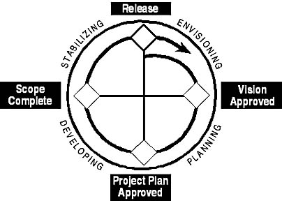
Figure 1.1 The MSF Development Process Model
The MSF Development Process Model has three primary traits:
- A phased process (the four wedges of the diagram in Figure 1.1)
- A milestone-driven process (the diamonds separating the phases)
- An iterative process (the process arrow aiming back into the first phase)
Although Figure 1.1 shows the four phases as quarters, the phases do not necessarily require equal amounts of time to complete. Different business and technological environments will require different time and resource ratios for the various phases.
Phased Process
The MSF Development Process Model consists of four interrelated phases. Each of these phases represents deliverables for which a baseline should be established before the development process can move to the next phase of the project. The four phases and their primary tasks are:
- Envisioning, which must produce a shared vision.
- Planning, which must produce a detailed project plan and application architecture.
- Developing, which must produce a well-built, complete product.
- Stabilizing, which must produce a stable, deployable product.
Milestone-Driven Process
The MSF Development Process Model is based on milestones that are points for review and synchronization, rather than points for freezing the application or its specifications. They enable the team to assess the project's progress and make midcourse corrections, such as adjusting the scope of the project to reflect changing customer requirements, or reacting to risks that might materialize during the course of the project.
The MSF Development Process Model uses two types of milestones: major milestones and interim milestones. Each milestone, whether major or interim, is marked by one or more deliverables. Deliverables are physical evidence that the team has reached a milestone.
Major Milestones
Each phase of the development process culminates in an externally visible major milestone. Externally visible means that the milestone and its deliverables are visible to entities outside the project team, such as the customer or operations personnel.
A major milestone is a point in time when all team members synchronize their deliverables. Additionally, those external to the project team such as the customer and users; operations, support, and help desk personnel; the distribution channel (commercial software); and other key project stakeholders, should be updated on the project status.
A significant role of major milestones is to allow for a stage-by-stage assessment of the project's viability. The project team and the customer, having reviewed the deliverables for the current phase, jointly make the decision whether or not to move into the next phase. Thus, major milestones serve to move the project from one phase to another.
Interim Milestones
Within each phase of the MSF Development Process Model are various interim milestones which, like major milestones, are review and synchronization points rather than freeze points. Unlike major milestones, however, interim milestones are internally visible—that is, visible only to project team members.
Interim milestones indicate early progress and break large work assignments into smaller pieces that are easier to address.
Versioned Process
The MSF Development Process Model is a versioned process in the sense that it is designed to be repeated during the life cycle of a given product. Each succeeding completion of the MSF Development Process Model allows for the addition of features and functionality to satisfy changing business requirements.
Using the MSF Application Model
An application model is a conceptual view of an application that establishes the definitions, rules, and relationships that will structure the application. Additionally, an application model serves as a basis for exchanging ideas during the logical design (rather than the physical design) of an application. The application model shows how the application is structured, not how it will be implemented.
The MSF Application Model provides a multi-layer services-based approach to designing and developing software applications. MSF views an application at a logical level as a network of cooperative, distributed, and reusable services that supports a business solution. Application services are units of application logic that include methods for implementing an operation, function, or transformation. These services should be accessed through a published interface that is driven by the interface specification, and focus value toward the customer rather than the provider. Services should map directly to user operations.
The MSF Application Model is Microsoft's recommended approach to designing distributed, multi-tier client-server applications. This model aims to:
- Promote a consistent approach to design and development of client-server applications.
- Provide a standard set of definitions for the application logic in a multi-layer application.
- Make it easier to use component technology to implement distributed, multi-tier applications that have the flexibility, scalability, and maintainability needed to address the needs of mission-critical, enterprise-wide applications.
- Shift from the traditional view of monolithic applications supporting specific business processes to the concept of systems of interoperable applications built upon a common set of components.
- Describe a way of consistently applying the skills and resources of an application development organization across multiple projects.
- Define a framework for organizing teams, introducing parallelism into the development process and identifying the required skills.
The MSF Application Model describes applications as using three services: user, business, and data. A service is a unit of application logic that implements operations, functions, or transformations applied to objects. Services can enforce business rules; perform calculations or manipulations on data; and expose features for entering, retrieving, viewing or modifying information. These services allow for parallel development, improved use of technology, easier maintenance and support, and flexibility in distributing the application's services. In addition, these services can reside anywhere in the environment, from a single desktop to servers and clients around the world.
Application Architectures
An application architecture is a conceptual view of the structure of an application. As shown in Figure 1.2, each application has three distinct layers: the user layer, the business layer, and the data layer. Each application also contains the following types of code: presentation, business-rule processing, data processing, and data storage. Application architectures differ in how this code is packaged to form a particular application product.
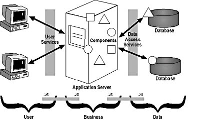
Figure 1.2 The Application Model and its application layers
Many current applications have a two-tier architecture, also known as client/server architecture. In a two-tier architecture, a client process handles the data processing and presentation parts of the application. Data is stored on centrally administered server computers. Clients connect directly to the servers they need, often for the lifetime of the application's use.
Client/server applications work well in controlled environments in which the number of users can be estimated and managed, and resources can be allocated accordingly. However, when the number of users is unknown or very large, the client/server architecture breaks down. Because each client connects to data servers directly, the number of available data connections limits scalability. Opportunities for reuse are limited because the clients are bound to the database formats. Each client application contains data processing logic, making the applications relatively large. (This type of client is sometimes called a fat client.) If the data processing logic ever needs to change, new applications must be distributed to every client computer.
A slight improvement comes from moving parts of the data processing, or business logic, to the data servers—for example, by using SQL Server stored procedures. This architecture is sometimes called "two-and-a-half tier." Applications built on this model are somewhat more scalable, but not scalable enough to meet the needs of highly distributed applications. In addition, opportunities for reuse are limited.
Scalability and reuse can be improved significantly by introducing a third tier to the application architecture. With multi-layer architecture, also known as N-tier architecture, the user, business, and data tiers are logically separated, as illustrated in Figure 1.3.

Figure 1.3 Multi-layer application architecture
The three tiers perform the following functions:
- User layer The user layer presents data to the user and, optionally, lets the user edit data. The two main types of user interfaces (UIs) for personal computer-based applications are native and Web-based. Native UIs use the service of the underlying operating system. On the Microsoft Windows platform, for example, native UIs use the Microsoft Win32 API and Windows controls. Web-based UIs are based on HTML and Extensible Markup Language (XML), which can be rendered by a Web browser on any platform.
- Business layer The business layer is used to enforce business and data rules. The presentation tier uses the services of the business tier. However, the business tier is not tied to any specific client; its services are available to all applications. Business rules can be business algorithms, business policies, legal policies, and so on—for example, "Users get a 10 percent discount for ads placed before Tuesday night" or "Six percent sales tax must be collected for all orders delivered to the Commonwealth of Kentucky." Data rules help to ensure the validity and occasionally the integrity of the stored data—for example, "An order header must have at least one detail record" or "Money must not be lost or generated during transfers between bank accounts." Business rules are typically implemented in isolated code modules, which are usually stored in a centralized location so that multiple applications can use them.
- Data layer The business tier has no knowledge of how or where the data it works on is stored. Instead, it relies on the data access services, which perform the actual work of storing and retrieving the data. The data access services are also implemented in isolated code modules, encapsulating knowledge of the underlying data store. If the data store moves or changes format, only the data access services need to be updated. Each data access module typically is responsible for the integrity of a set of data—for example, data placed in relational tables or the Microsoft ActiveX Data Objects (ADO) and OLE DB technology. For the purpose of N-tier design, the data store is simply the DBMS—the systems required to serve data from tables, as well as optimize information retrieval, such as database indexes. Examples of data stores are SQL Server, Microsoft Exchange Server, Microsoft Database Engine (MSDE), Microsoft FoxPro, Microsoft Access, and Microsoft Jet.
It might be slightly confusing to talk about logical architecture as part of the Physical Model. It is important to understand that logical architecture encompasses a wide range of physical architectures and implementations that specify where services are deployed. In other words, applications are constructed as logical networks of consumers and suppliers of services. Services are merely units of application logic that provide well-defined functionality.
The terms multi-layer and N-tier don't imply separate computers. The N-tier application architecture promotes scalable applications. To create highly scalable applications, resources such as database connections must be shared. Instead of each client application consuming resources to access data servers directly, client applications communicate with business services. One instance of a business service can support many clients, reducing resource consumption and improving scalability, as shown in Figure 1.4 and Figure 1.5. Because business services do not manage data directly, it's easy to replicate these services to support even more clients. Services can often be designed and implemented independently of any particular client applications, providing flexibility and the potential for reuse in many applications. By encapsulating application logic behind well-defined public interfaces, developers create a body of reusable services that can easily be combined in new ways to create new applications. In addition, common functionality can easily be updated in response to changing business requirements, without impacting the client applications that rely on the functionality. This aspect reduces the management and deployment costs of changing requirements.

Figure 1.4 Client/server systems
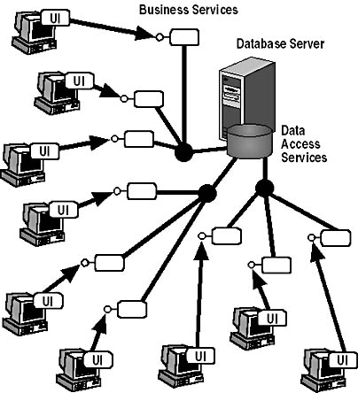
Figure 1.5 N-tier systems
The multi-layer application architecture can also help developers deal with existing, or legacy systems. Developers can "wrap" access to existing systems within business logic, data access, or data store services. Client applications need to worry only about how to access the business logic, not about how to access all the different legacy systems on which they might rely. If the legacy system is modified or replaced, only the wrapper needs to be updated.
Using the MSF Design Process Model
The MSF Design Process consists of three distinct types of design work: conceptual, logical, and physical. Each of these generates a model of the same name: the Conceptual Design Model, the Logical Design Model, and the Physical Design Model.
Each part of the process approaches the design task from a different perspective and defines the solution differently, as shown in Table 1.2.
Table 1.2 Design task approaches to the three parts of the MSF Design Process
| Type of design work | Perspective | Action |
|---|---|---|
| Conceptual | Views the problem from the perspective of the user and business | Defines the problem and solution in terms of scenarios |
| Logical | Views the solution from the perspective of the project team | Defines the solution as a set of cooperating services team |
| Physical | Views the solution from the perspective of the developers | Defines the solution's services and technologies |
The output of each part is used as the input for the succeeding part, as Figure 1.6 illustrates.
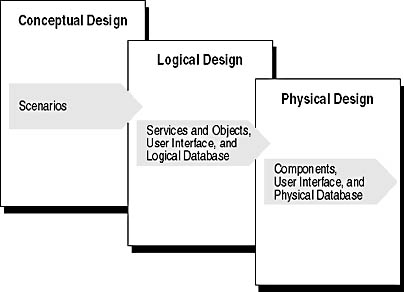
Figure 1.6 The output of the three interdependent design process models
The goals of the three parts are:
- Conceptual Design Identify business needs and understand what users do and what they require. Conceptual Design generates scenarios that reflect complete and accurate requirements by involving the customer, users, and other stakeholders.
- Logical Design Organize the solution and the communication among its elements. Logical Design takes the business problem identified in Conceptual Design scenarios and formulates an abstract model of the solution. Following the workflow in Figure 1.6, Logical Design takes the scenarios from Conceptual Design and produces objects and services, UI prototypes, and a logical database design.
- Physical Design Apply real-world technology constraints, including those dealing with implementation and performance, to the output of Logical Design by specifying the details of the solution. The output of Logical Design is used to produce components, UI specifications, and physical database design.
The MSF Design Process moves from tangible requirements (use cases) to an abstract application design (Conceptual Design), then to a rationalized application design (Logical Design), then to a concrete application design (Physical Design), and finally, to the tangible product. Conceptual Design is the initial translation of the use cases (the language of the users) to the application design (the language of the application developers). Logical Design is the developers' perspective and serves as a translator between the high-level application concepts—the business and user requirements—and the detailed application design.
Conceptual Design does not take into account the approach or the technologies needed to build the solution. Rather, Conceptual Design corresponds to rough sketches and scenarios for building a house. These elements are easily understood models jointly created by the customer, user, and architect. Conceptual Design is the translation of business and user requirements from the language of the users to the language of the developers.
Logical Design starts to get into the details of the application that the team will build to fulfill business needs and user requirements. Logical Design thus corresponds to the floor plan and elevation of a house, where elements such as spatial relationships are organized. In this part of the process, the architect's team lays out the design's relationships and communication paths.
Physical Design addresses the technology that will be used. This design adds detail to the architecture and reflects real-world implementation constraints.
Essentially, the different parts of the MSF Design Process address the needs of different "readers" while still serving as parts of a functional whole. Instead of forcing readers to digest what might be a very large and detailed document, this model allows readers to focus only on the information—the part of the whole—that is pertinent to them. The model also allows the use of formal or informal techniques as appropriate.
The design evolves as each step in the process contributes more detail to the Functional Specification. And as the design evolves, every aspect is traceable from any point back to the original business problem, for verification and testing purposes.
Although the MSF Design Process resides primarily within the Planning Phase of the MSF Development Process Model, the work of design often begins before the Planning Phase is officially started, and it continues to some extent up to the point when the code is frozen (near the end of the Developing Phase). The baselines for each of the three parts of the process are established during the Planning Phase. As shown in Figure 1.7, the three design activities occur in a staggered, parallel manner, with the early output of one activity signaling that the next activity should begin.
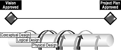
Figure 1.7 The overlapping, iterative, and spiral qualities of the MSF Design Process
The Conceptual Design activity begins when the team agrees upon a vision statement, which can occur before the team reaches the formal Vision Approved Milestone. The Logical Design and Physical Design activities parallel those of Conceptual Design, and all three sit squarely in, but are not limited to, the Planning Phase of the MSF Development Process Model.
It is the parallel execution of all three design activities that allows the product's conceptual, logical, and physical design to have the following three qualities:
- Overlapping The activities are parallel, with Conceptual Design typically starting first, followed by Logical Design and then Physical Design. They are not sequential, so one doesn't have to finish before the next can begin. In fact, Logical Design and Physical Design can begin even before the baseline for Conceptual Design is established.
- Iterative The activities have their own cycles of validation, design testing (as opposed to code testing), and redesign.
- Spiral Each iteration of all three activities represents progress toward the Project Plan Approved Milestone of the Planning Phase.
Obviously, a minimum degree of sequencing must occur as a practical matter. Conceptual Design must start before Logical Design, which must start before Physical Design. Similarly, the baseline for Conceptual Design must be established before the baseline for Logical Design, which must be established before the baseline for Physical Design.
Design Considerations
The promotion of understanding among members of the project team is a primary consideration when determining how to manage the inherent complexity of large-scale business applications and when trying to assess the level of detail that should be included in the design. If too little detail is included, the team runs the risk of missing relevant interactions. If too much detail is included, the design might become overly complicated.
The experience and skill of C++ developers are especially valuable to the logical design process, as the principles of object-oriented software development are very similar to the methods used to establish a logical design. This section outlines some of the key concepts used in the logical design process—concepts that will be familiar to anyone with experience in developing object-oriented software solutions.
Modularity
The team starts the Logical Design process by defining the major services of the system. A service represents some collection of processes that work together to accomplish a task. The principle behind modular design is that the final product will be constituted by the combination of the major services. Each service is deliberately designed to perform a particular function as a stand-alone unit that must work with other parts of the system.
Abstraction
Abstraction is the process of examining and distilling the properties and features of a distinct item, and the classification of groups of items through the recognition of essential common characteristics. Abstraction enables us to classify and organize our day-to-day world by concentrating on the defining characteristics and behavior of an object while ignoring its non-essential details. This process enables us to deal with what would otherwise be overwhelmingly complex situations.
Typically, C++ developers are accustomed to abstracting real-world objects, and more abstract entities, into classes that specify the characteristics of the software objects in the application. For example, designers of a postal delivery system might design classes to represent letters, packets, van routes, and airline schedules; as 4well as entities internal to the software environment such as caches, event schedulers, and barcode input handlers.
Encapsulation
Encapsulation is a fundamental principle of structured design, object-oriented design, and object-based component design. In structured design, encapsulation provides the notion of a "black box"—a compiled, unit-tested module that can be assumed to perform a limited, well-defined function correctly. In object-oriented design, it provides the basis for abstraction. Abstraction focuses upon the essential characteristics of some object, relative to the perspective of the viewer. Software components encapsulate behaviors, which they expose as services to client programs.
Encapsulation is the technique for packaging information (data and process) in such a way as to hide what should be hidden, and make visible what is intended to be visible. A component should describe the services that it can provide and specify the data types of the input and output parameters. It should not expose the means by which it provides its advertised services—in particular, it should ensure that its inner state is not exposed in such a way that it can be corrupted by external factors.
When developers decide to expose some aspect of a component, they use an interface. An interface describes the services that a component can provide to a client. To ensure that a component is easy to use, and difficult to abuse, it should hide as much as possible about its inner workings from the outside world.
Encapsulation allows a system to be assembled out of parts. The idea of encapsulation is applicable at all levels of design—from the largest subsystem to the smallest code routines and functions.
Cohesion and Coupling
Cohesion refers to how closely the operations within a service are related. The goal of any design is to maximize the beneficial cohesion among its constituent parts. High cohesion allows a module's purpose or function to be more easily abstracted so that its behavior can be more easily and accurately specified.
Coupling refers to the relationships between services. The less information that links services to each other, the freer the designer is to compose a solution without causing perturbations within the individual services themselves, or the existing assembly of those services. One service should depend as little as possible on other services. However, where a dependency exists, the connection between those services should be as clear and straightforward as possible. This leads to easier definition and greater simplicity in determining interfaces.
The constituent units of a well-defined service have loose inter-unit coupling and high internal cohesion. As an example, consider a hi-fi music system built of three separate services—an amplifier, a CD player, and a tape deck. The internal components of the amplifier, such as the transistors and the resistors, don't do much on their own. They rely upon a relationship of high internal cohesion with the other parts of the amplifier module to perform their task. On the other hand, the modular units of the hi-fi system exhibit a loosely coupled relationship—they are usually connected together by a few cables, and can easily be interchanged.
Separation of Interface and Implementation
Services exhibit external characteristics that make them available as building blocks. Each service has an interface that allows it to be used, but the interface hides internal implementations so those implementations can be replaced without affecting the rest of the system. For this approach to work effectively, developers must recognize that each service contains some capability that needs to be represented to the outside world. A description of this capability can be used as a contract with other modules. Any other service that complies with this contract can access the capability.
A contract sets up the rules for interaction between the supplier and the consumer. For example, we know that when we use a public telephone, we have to insert some coins and dial a number. We trust that if we do this correctly, the call will be connected or, if the call is unsuccessful, the money will be returned. Likewise, users of a software component know that as long as the conditions of the interface "contract" are met, any consumer can call upon it as a supplier and receive the specified service. This is known as an open-ended contract. It is important that interfaces be designed as open-ended as possible to facilitate modularity and reuse.
The interface is defined logically, independent of its implementation, providing common access to any potential user. The contractual nature of the interface places the responsibility for fulfilling the request on the supplier of that capability. If we type the number correctly, it is the phone company's responsibility to handle the necessary details to connect us to the intended party. Interface implementations are replaceable as long as the replacement can service the same public interface. This allows services to evolve as conditions and requirements change, or as improvements are made. For example, the phone company can often upgrade the handset in a telephone booth. As long as it maintains the familiar dial pad and coin slot interface, we can continue to use the handset without difficulty.
Clearly specifying interfaces is necessary for services to be designed and coded independently. With well-defined interfaces, these independently coded services can be reliably integrated into a fully functional application. The inter-service independence afforded by clearly specified interfaces allows for easier maintenance and greater flexibility with regard to future upgrades.
Developing Desktop Applications
In this course, we will be applying the Application Model in the creation of desktop applications. By "desktop applications," we do not just mean applications like Microsoft Word that run self-contained on a single computer. We define desktop applications to include client/server applications—particularly those based on the so-called "fat client model," where the business services and the presentation services are implemented together as a locally deployed appli-cation retrieving data from a remote data source. This model tends to assume business rules of limited complexity and of limited deployment scope.
Where appropriate, a desktop application should make use of the component-based design described by the Application Model to take advantage of the flexibility, scalability, and reliability offered by a component-based architecture.
Lesson Summary
MSF is a suite of models, principles, and guides for building and deploying software. MSF is a collection of best practices used by the Microsoft product groups and Microsoft Consulting Services.
MSF implements the following models and perspectives, which contribute to the development cycle:
- MSF Development Team Model Defines a team of peers working in interdependent and cooperating roles.
- MSF Development Process Model Helps the team establish guidelines for planning and controlling results-oriented projects based on project scope, the resources available, and the schedule.
- MSF Application Model Helps the team design distributed applications that take optimum advantage of component reuse. It establishes standards and guidelines for designing distributed client/server and multi-tier applications that can be implemented using Microsoft's component-based tools and technologies.
- MSF Design Process Model Shows how applications must be designed from both a user and business perspective. It specifies three iterative design phases, tying together the Team Model, Process Model, and Application Model in a solution-oriented context.
- Conceptual design perspective Focuses on the needs and technological capabilities of the business and of the users. The output of conceptual design is typically documented as scenarios.
- Logical design perspective Focuses on project team understanding. The solution is described in terms of the constituent parts of the system and how they interact. The output of logical design consists of high-level functional specification documents.
- Physical design perspective Focuses on providing information necessary to allow developers to implement the solution. Physical design focuses on the organization, structure and technology of the solution. The output of physical design consists of lower-level specification documents such as flowcharts, object models, and pseudocode.
Sometimes developers participate only in the physical design of a solution. However, logical design should not be neglected, as it plays an important role in software development. The purpose of the logical design process is to promote a greater understanding of the system by the entire project team, helping team members to determine how to manage the inherent complexity of large-scale business applications. Management of this complexity is achieved through the application of design concepts similar to those employed by object-oriented software developers.
EAN: 2147483647
Pages: 95