Lesson 2: Hard Disk Drives
Hard disk drives are mass storage devices. Virtually all of today's computers have at least one hard disk drive. The first hard disk drives were small in capacity, physically large, and expensive, by today's standards; they were about 4 inches tall, 5.25 inches wide, 8 inches long, and weighed almost 10 pounds. In 1981, IBM introduced the XT computer with a 10-MB hard drive, and new owners wondered what they would do with all that space. Today, a new hard disk drive can fit in your pocket and hold over 17 GB of data. In this lesson, we examine hard disk drives, from the early versions to today's mini-monsters.
After this lesson, you will be able to:
- Explain the operation of a hard disk drive.
- Define the different types of hard disk drives, including their advantages and disadvantages.
- Partition a hard disk drive.
- Troubleshoot hard disk drives.
Estimated lesson time: 45 minutes
Physical Characteristics

Run the hdrive video located in the demos folder on the CD accompanying this book to view a presentation of the inner workings of a hard disk drive.
The first form of PC mass storage was the magnetic tape drive. Although tape proved a good medium for storing large amounts of data, it had some significant limitations. The typical cassette drive cartridge was easily damaged. Further, gaining access to the data was slow due to the way data is organized on tape, as a long stream of ones and zeroes, an arrangement known as "sequential." Because tapes were hundreds of feet long, users often had to run the entire length of the tape to find the data they were seeking. Although by providing random access (the ability to go directly to any point on the data surface), floppy disks are a major improvement, they are too slow and too limited in capacity for modern applications.
The original concept behind the hard disk drive was to provide a storage medium that held large amounts of data and allowed fast (random) access to that data. Data on a hard drive can be accessed directly, without requiring the user to start at the beginning and read everything until finding the data sought.
The first IBM hard disk drives came out in the late 1970s and early 1980s and were code-named "Winchester." The original design concept included two 30-MB units in one enclosure: 30-30 (hence "Winchester"). The PC-XT was the first personal computer to include a hard disk. They were called "fixed disks" because they were not removable. (Old mainframe computers had hard platters that were removable.) The Winchester technology is the ancestor of all PC fixed disks.
Hard disk drives are composed of several platters, matched to a collection of R/W heads and an actuator. Unlike floppy disk drives, a hard disk drive assembly is housed in a sealed case, which prevents contamination from the surrounding environment. Each case has a tiny aperture with an air filter. This allows the air pressure to be equalized between the interior and the exterior of the drive.
The platters are usually made of an aluminum alloy and have a thin magnetic-media coating on both sides. After coating, the platters are polished and given another thin coating of graphite for protection against mechanical damage caused by physical contact between the data heads and the platter surface.
The R/W heads "float on a cushion of air" above the platters, which spin at 3500 to 12,000 rpm. The distance (flying height) between the heads and the disk surface is less than the thickness of a fingerprint.
Storing Data
As noted in previous chapters, data is stored using binary code. Within the computer's memory, ones and zeroes are stored as electrical impulses. On magnetic media, the ones and zeroes can be stored as either magnetic or nonmagnetic areas on the drive surface. Although there are magnetized and nonmagnetized positions on the hard disk drive, the ones and zeroes of the binary code are stored in terms of flux reversals. These flux reversals are actually the transitions between magnetized and nonmagnetized positions on the hard drive surface.
Early hard disk drives used a method of encoding called FM (frequency modulation). FM technology is based on timing. To differentiate a 1 from a 0, it measures the time the drive head spends in a magnetized state. For FM to work, it requires every 1 or 0 to be preceded by a timing bit. The early FM drives worked well, but all the extra bits added to the work and slowed the process of data transfer. In order to improve efficiency and speed of the data transfer, the FM was replaced by an improved version that reduced the number of timing bits required. This new technology was called MFM (modified frequency modulation). MFM uses the preceding data bit to indicate whether the current bit is a 1 or a 0, thus reducing the number of timing bits by more than 50 percent.
Another method used to place data on hard disk drives is run-length limited (RLL) encoding. RLL replaces the timing bits with patterns of 1s and 0s that represent longer patterns of 1s and 0s. Although this looks inefficient, the elimination of the timing bits speeds overall performance.
TIP
Unless you're working with hard disk drives manufactured before 1989, it is not necessary to know which type of data encoding is used.
Actuator Arms
The goal of a hard disk drive is to quickly and directly access data stored on a flat surface. To do this, two different motions are required. As the disk spins, the R/W heads move across the platter perpendicularly to the motion of the disk. The R/W heads are mounted on the ends of the actuator arms (much like the arm of an old record player). A critical element in hard disk drive design is the speed and accuracy of these actuator arms.
Early hard disk drives used a stepper motor to move the actuator arms in fixed increments or steps. This early technology had several limitations:
- The interface between the stepper motor and actuator arm required that slippage be kept to a minimum. The greater the slippage, the greater the error.
- Time and physical deterioration of the components caused the positioning of the arms to become less precise. This deterioration eventually caused data transfer errors.
- Heat affected the operation of the stepper motor negatively. The contraction and expansion of the components caused positioning accuracy errors. (Components expand as they get warmer and contract as they cool. Even though these changes are very small, they make it difficult to access data, written while the hard drive is cold, after the disk has warmed up.)
- The R/W heads need to be "parked" when not in use. Parking moves the heads to an area of the disk that does not contain data. Leaving the heads on an area with data can cause that data to be corrupted. Old hard disk drives had to be parked with a command. Most drives today automatically park the heads during spin-down.
NOTE
Older hard disk drives require that the heads be parked before moving the computer. It is recommended that you use the appropriate command to park the heads. The actual command can vary depending on the drive manufacturer, but you can try typing PARK at an MS-DOS prompt.
Hard disk drives with stepping motor actuator arms have been replaced by drives that employ a linear motor to move the actuator arms. These linear voice coil motors use the same type of voice coil found in an audio loudspeaker, hence the name. This principle uses a permanent magnet and a coil on the actuator arm. By passing electrical current through the coil, it generates a magnetic field that moves the actuator arm into the proper position.
Voice coil hard disk drives offer several advantages:
- The lack of mechanical interface between the motor and the actuator arm provides consistent positioning accuracy.
- When the drive is shut down (the power is removed from the coil), the actuator arm, which is spring-loaded, moves back to its initial position, thus eliminating the need to park the head. In a sense, these drives are self-parking.
There is a drawback: because a voice coil motor can't accurately predict the movement of the heads across the disk, one side of one platter is used for navigational purposes and so is unavailable for data storage. The voice coil moves the R/W head into an approximate position. Then the R/W heads on the reserved platter use the "map" to determine the head's true position and make any necessary adjustments. This is why hard drive specifications list an odd number of heads.
Head to Disk Interference
Head to Disk Interference (HDI) is a fancy term for head crash. These terms describe the contact that sometimes occurs between the fragile surface of the disk and the R/W head. This contact can cause considerable damage to both the R/W head and the disk. Never move a hard disk drive until it is completely stopped; the momentum of the drive can cause a crash if it is moved or dropped during operation.
Picking up a disconnected hard disk drive that is still spinning is not a good idea either. The rotation force of the platters can wrench it out of your hands, and the drive is not likely to survive the trip to the floor.
Geometry
Hard disk drives are composed of one or more disks or platters on which data is stored. The geometry of a hard drive is the organization of data on these platters. Geometry determines how and where data is stored on the surface of each platter, and thus the maximum storage capacity of the drive. There are five numerical values that describe geometry:
- Heads
- Cylinders
- Sectors per track
- Write precompensation
- Landing zone
Write precompensation and landing zone are obsolete, but often seen on older drives. Let's take a look at each of these components.
TIP
All hard disk drives have geometry. Knowledge of the geometry is required to install or reinstall a hard drive.
Heads
The number of heads is relative to the total number of sides of all the platters used to store data (see Figure 8.5). If a hard disk drive has four platters, it can have up to eight heads. The maximum number of heads is limited by BIOS to 16.
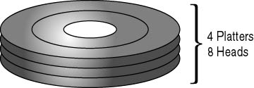
Figure 8.5 Drive heads
Hard disk drives that control the actuator arms using voice coil motors reserve a head or two for accuracy of the arm position. Therefore, it is not uncommon for a hard disk drive to have an odd number of heads.
Some hard disk drive manufacturers use a technology called sector translation. This allows some hard drives to have more than two heads per platter. It is possible for a drive to have up to 12 heads but only one platter. Regardless of the methods used to manufacture a hard drive, the maximum number of heads a hard drive can contain is 16.
Cylinders
Data is stored in circular paths on the surface of each head. Each path is called a track. There are hundreds of tracks on the surface of each head. A set of tracks (all of the same diameter) through each head is called a cylinder (see Figure 8.6). The number of cylinders is a measurement of drive geometry; the number of tracks is not a measurement of drive geometry. BIOS limitations set the maximum number of cylinders at 1024.
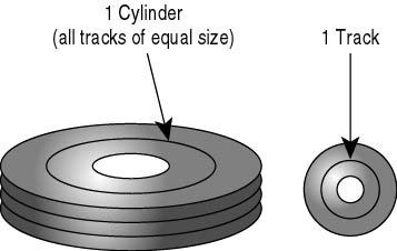
Figure 8.6 Cylinders
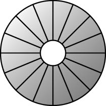
Sectors per Track
A hard disk drive is cut (figuratively) into tens of thousands of small arcs, like a pie. Each arc is called a sector and holds 512 bytes of data. A sector is shown in Figure 8.7. The number of sectors is not important and is not part of the geometry; the important value is the number of sectors per track. BIOS limitations set the number of sectors per track at 63.
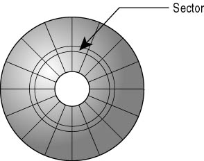
Figure 8.7 Sector
Write Precompensation
All sectors store the same number of bytes: 512; however, the sectors toward the outside of the platter are physically longer than those closer to the center. Early drives experienced difficulty with the varying physical sizes of the sectors. Therefore, a method of compensation was needed—the write precompensation value defines the cylinder where write precompensation begins.
NOTE
The write precompensation value is now obsolete, but is often seen on older drives.
Landing Zone
A landing zone defines an unused cylinder as a "parking place" for the R/W heads. This is found in older hard disk drives that use stepper motors. It is important to park the heads on these drives to avoid accidental damage when moving hard disk drives.
CHS Values
Cylinders, heads, and sectors per track (see Figure 8.8) are known collectively as the CHS values. The capacity of any hard disk drive can be determined from these three values.
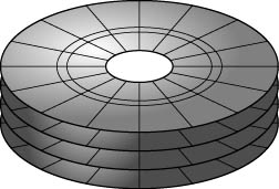
Figure 8.8 Cylinders, heads, sectors per track
The maximum CHS values are:
- 1024 cylinders.
- 16 heads.
- 63 sectors per track.
- 512 bytes per sector.
Therefore, the largest hard disk drive size recognized directly by the BIOS is 504 MB. Larger drive sizes can be attained by using either hardware or software translation that manages access to the expanded capacity without direct control by the system BIOS.
1024 x 16 x 63 x 512 bytes/sector = 528,482,304 bytes (528 million bytes or 504 MB)
There are many hard disk drives that are larger than 504 MB. These drives manage to exceed this limitation in one of two ways: either they bypass the system BIOS (by using one of their own) or they change the way the system BIOS routines are read. (For a fuller discussion of this, refer to Chapter 9, "High-Capacity Disk Drives.")
Hard Disk Drive Types
The original personal computer design did not include hard disk drives. Hard disk drives were reserved for large mainframe computers and remained highly proprietary in design. Today, there are four types of hard drives, each with its own method of installation.
ST506
The very first hard disk drives for personal computers used the ST-506/412 interface. It was developed by Seagate Technologies in 1980 and originally appeared with the 5-MB ST-506 drive. The ST-506 was priced at $3,000 and had a capacity of 5 MB. The ST-506/412 was the only hard drive available for the IBM computer and was the first to be supported by the ROM BIOS chip on the motherboard.
ESDI
The ESDI (Enhanced Small Device Interface) was introduced in 1983 by the Maxtor Corporation. This technology moved many of the controller functions directly onto the hard disk drive itself. This greatly improved data transfer speeds. Some ESDI controllers even offered enhanced command sets, which supported autosensing of the drive's geometry by the motherboard's ROM BIOS. The installation of ESDI drives was almost identical to the installation of ST-506 drives. The high cost of ESDI drives and advances in other drive technologies spelled their doom. Today they are obsolete.
IDE/EIDE
The IDE (Integrated Drive Electronics) drive arrived on the scene in the early 1990s and incorporated the benefits of both its predecessors. IDE quickly became the standard for computers. It supports the ST-506 standard command set, and its limited controller functions build directly on the drive's logic board. This results in a much less expensive design. Most new motherboards have the IDE connections built in; thus, the chips are part of the board design.
Western Digital and Compaq developed the 40-pin IDE ISA pinout specification. ANSI (the American National Standards Institute) standards committees accepted the standard as the Common Access Method (CAM) AT. The official name for these drives is now ATA/CAM (AT Attachment/Common Access Method). The terms IDE and ATA/CAM are interchangeable.
Enhanced IDE (EIDE) adds a number of improvements to the standard IDE drives, including:
- Increased data throughput.
- Support of storage devices other than hard disk drives.
- Up to four IDE devices instead of just two. This actually allows the BIOS to support two controllers (each with two drives).
- Support for hard disk drives larger than 528 MB.
NOTE
EIDE is the standard for most hard disks in today's personal computers. A new type of EIDE, U-DMA 66, doubles the base speed of existing EIDE drives on motherboards that have a 66-MHz bus (hence the name).
SCSI
The Small Computer System Interface or SCSI (pronounced scuzzy) has been around since the mid-1970s in one or more forms. It is the most robust of the hard disk drive interfaces, and is popular on network servers and high-performance workstations. Apple adopted SCSI as its expansion bus standard. The original SCSI standard allowed up to seven peripheral devices to be daisy-chained (connected in a series) to one common bus through a single host adapter connected to the computer bus. SCSI-2 upped that to 15, and some adapters allow multiple chains for even more devices.
The SCSI bus functions as a communications pathway between the computer system bus and the SCSI device controller. That improves performance, because the card takes over the low-level commands and frees the system bus during operations that do not involve RAM. A SCSI adapter uses its own BIOS and firmware to talk to its devices, then uses a software interface layer and drivers to communicate with the operating system. There are two software interface layers: ASPI (Advanced SCSI Programming Interface) and CAM (Common Access Method). CAM is now obsolete, and ASPI comes with Windows and other operating systems. In most cases, you won't have to worry about loading the drivers unless you are updating them or installing a new card that does not have native drivers available to the operating system.
NOTE
Most SCSI cards can be configured to mimic the ST-506 hard disk drive and talk directly to the PC BIOS. This lets you install a SCSI hard drive without additional drivers. You will need the ASPI or CAM software to get full use of advanced SCSI performance features or to attach non-hard disk drive SCSI peripherals to the system.
SCSI usually costs more than other hard disk drive interfaces, but is the only one that allows both internal and external connections on the same adapter. It also allows you to attach more types of devices than any other interface. A single chain can include hard drives, CD-ROM and other optical drives, scanners, and tape drives.
Installation and Setup
All boot devices must be configured outside the operating system (Windows 95 and 98, Windows NT, or MS-DOS) regardless of the level of Plug and Play compatibility. (Devices such as disk drives and CD-ROMs that are used to boot must be configured at the BIOS and hardware level because they typically contain the operating system and must run properly before the operating system can be started.)
Installation of a hard disk drive consists of five simple steps:
- Physical installation and cabling
- CMOS setup
- Low-level formatting (if required)
- Partitioning
- Formatting
Cabling
Just as there are different types of drives, there are different cabling requirements for each. Let's look at the three most common types.
ST-506
The ST-506 uses a 34-connector control cable (daisy-chained for dual drives) and a 20-connector data cable for each drive. The 34-wire control cable has a twist in it for line 25 through 29 configuration (similar to the floppy disk drive cable); this twist determines which hard disk drive is hard drive 0 and which is hard drive 1. The drive at the end is drive 0.
IDE/EIDE
The IDE uses a simple 40-pin cable that plugs into the controller and into the drive (see Figure 8.9). There are no twists. IDE controllers identify the two drives as either master or slave. Drive makers use different methods to set up their drives. The most common system uses jumpers. Setting these jumpers serves the same function as the twist used with other drive cables: it identifies whether the drive is master or slave. Other drives use switches, and some new drives use software to determine which is the dominant drive. Be sure to check the manufacturers' specifications to properly set up the drive.
U-DMA 66
A special version of the 40-pin IDE cables is used for U-DMA 66. Be sure to obtain and install it if you are working with one of these newer drives. It is also 40-pin, but has a blue connector on one end and a black one on the other. All the other installation and cabling procedures are the same as for traditional IDE devices.
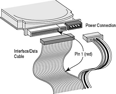
Figure 8.9 IDE connections
TIP
When installing a new secondary hard disk drive in a system, be sure to set the new drive as slave and verify that the first drive is set to master. The documentation supplied with the drive should provide the necessary information. Often, this information is printed on the label of the drive. Both drives must be properly configured before the system is started. If the drives are not properly jumpered, they won't work.
If you don't know how to set the jumpers (see Figure 8.10), try calling the hard disk drive manufacturer (or look for its Web site on the Internet).
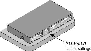
Figure 8.10 Master/slave jumper settings
Setting the System CMOS for the Hard Drive
After a hard disk drive has been installed physically, the geometry of the drive must be entered into the CMOS through the CMOS setup program before the PC will recognize the new device. This information must be entered exactly as specified by the manufacturer. Figure 8.11 shows hard disk drive configuration information in a typical CMOS. Figure 8.12 shows a subscreen of the main hard drive setup screen.
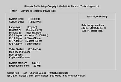
Figure 8.11 CMOS main screen
Originally, CMOS would allow for only two drives. Later versions allow up to four drives, because most new PCs have two IDE channels.
The CHS (cylinders, heads, sectors per track), along with write precompensation and landing zone, determine how the hard disk drive controller accesses the physical hard drive. The creators of the first CMOS routines for the 286 AT believed that the five different geometry numbers would be too complicated for the average user to configure, so they established 15 preset combinations of hard drive geometries. These preset combinations are called types. With types, the user simply enters a hard drive type number into the CMOS.
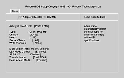
Figure 8.12 Hard disk drive setup screen
This system worked well for a period of time, but with each new hard disk drive that manufacturers designed, a new type also had to be created and added to the list. BIOS makers continued to add new types until there were more than 45 variations. To deal with this issue, Setup routines now include a user type. This allows manual entry of the geometry values, increasing both the flexibility and complexity of hard drive installation.
CMOS setup is easy with IDE drives. Most CMOS chips today have a setting known as IDE autodetection, which runs the identify drive command, gathering and setting the proper geometry values. To use it, simply connect the drive to the computer, turn it on, and run the CMOS. The identify drive command instructs the drive to transmit a 512-byte block of data containing the following information:
- Manufacturer
- Model and serial numbers
- Firmware revision number
- Buffer type indicating sector buffering or caching capabilities
- Number of cylinders in the default translation mode
- Number of heads in the default translation mode
- Number of sectors per track in the default translation mode
- Number of cylinders in the current translation mode
- Number of heads in the current translation mode
- Number of sectors per track in the current translation mode
IMPORTANT
Be sure to save your settings before you exit the setup program.
What happens if wrong data is entered into the CMOS? For example, what if a 1.2-GB hard disk drive is installed and the CMOS is set up to make it a 504-MB hard drive? When you boot the computer, you will see a perfect 504-MB hard drive. You will need to correct the entry to obtain proper use of the drive. It should not be left improperly entered, and it might not be accessible by the system.
If the computer you are working on does not support autodetection, you must be able to determine the geometry of a drive in order for it to be installed.
There are many ways to determine the geometry of a hard disk drive:
- Check the label. The geometry or type of many hard drives will be labeled directly on the hard drive itself.
- Check the documentation that came with the hard drive. All drives have a model number that can be used to obtain the geometry parameters either from the manufacturer or a third party. The hard drive manufacturers usually reserve a section of their Web site for providing configuration data and the setup utilities available for download.
- Contact the manufacturer. Many manufacturers have toll-free phone numbers.
After a drive is installed, it must be assigned a drive name or letter that is unique. There are several drive-naming conventions that help identify this unique name. If only one hard disk drive is installed, it must be configured as drive 0, or master. If a second drive is installed, it is recognized as hard drive 1, or slave. Many CMOS configurations use the terms C: and D:. Under all versions of MS-DOS and Windows, hard drive 0 is recognized as C; hard drive 1 is recognized as D.
As more drives are added to a system, (including tape, CD-ROM, and network drives), the names of existing drives might change. For example, installing a portable drive such as an Iomega Zip drive can change a CD-ROM from the D drive to the E drive. When the portable drive is removed, the CD-ROM will once again be the D drive. Keep in mind the difference between logical and physical drives. A physical drive is the hardware—it can be divided into two or more logical drives. (See the "Partitioning" section later in this lesson.) Drives on a network server are also logical drives. Write down the configuration and keep track as changes in the system are made. The only drive letters that are fixed are the A and B drives, which are always the floppy disk drives, and the C drive, the boot drive where the MS-DOS operating system resides.
NOTE
This confusion in drive letters can also confuse the operating system, making it hard or impossible for it to locate drivers. In such cases, you might need to reinstall the drivers before the system can make use of the affected hardware, and a Windows 95, 98, or 2000 machine might automatically start in Safe Mode. Check the System/Device manager option in the Control Panel after the PC is operational and look for duplicate hardware items or items with flags noting missing or inoperable conditions.
Low-Level Formatting
Low-level formatting means to create all the sectors, tracks, cylinders, and head information on the drive and is the third step in installing hard disk drives; generally it applies only to older drives. Low-level formatting by the end user has virtually been eliminated with today's drives (it's done at the factory).
A low-level format performs three simultaneous functions:
- It creates and organizes the sectors, making them ready to accept data.
- It sets the proper interleave (records the sector header, trailer information, and intersector and intertrack gaps).
- It establishes the boot sector.
Every hard disk drive arrives from the factory with bad spots on the platters. Data cannot be written to these areas. As the sectors are being created, the low-level format attempts to skip over these bad spots. Sometimes, it is impossible to skip over a spot so the sector is marked as "bad" in the ID field.
CAUTION
Low-level formatting is not required on IDE and U-DMA drives. Performing a low-level format on these devices might render the drive unusable. SCSI drives are low-level formatted using a utility that is built into the SCSI adapter card's firmware. Format a low-level drive only if it is absolutely necessary (for example, if a virus has contaminated the boot sector and that is the only remedy) and if you are sure you know and can follow the proper procedure! Remember, as soon as you issue the format command, all data on the drive will be lost.
IDE drives use a special type of low-level formatting called embedded servo. This type of low-level formatting can be done by the manufacturer only, or with a special utility provided by the manufacturer. When installing an IDE drive, go straight to the partitioning step after the CMOS is set up.
To continue with hard disk drive installation for MS-DOS and Windows 3.x and 95 and 98 versions, you will need a bootable floppy disk containing several programs that are required to prepare the new drive. (For Windows NT and 2000, alternate methods that are not part of the current A+ test are available. You can also use the procedure listed below to prepare a drive for use with those operating environments.)
To create a bootable floppy disk, a computer is required that has an installed working hard disk drive, or floppy disk drive, and a compatible operating system. Be sure to use the same operating system on the floppy disk as the one you'll use for the new drive.
Insert a floppy disk into the A drive and type:
format a: /s |
This will copy system files to the disk, making it a bootable disk.
The next step is to copy the necessary files from the MS-DOS directory to the floppy disk. The default location for these files is the C:\DOS directory for MS-DOS and the C:\Windows\Command directory for Windows 95 and 98. Copy these files:
format.com (or format.exe) fdisk.com |
This bootable disk can be used for partitioning and high-level formatting as discussed in the following sections.
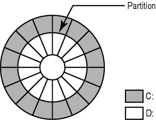
Partitioning
Partitions are logical divisions of a hard drive. A computer might have only one physical hard drive (called hard drive 0), but it can have anywhere from one to 24 logical drives, identified as C to Z.
Partitions exist for two reasons:
- To divide the disk into several drive letters to make it easier to organize data files. Some users separate data, programs, and operating-system files onto different drives.
- To accommodate more than one operating system.
When MS-DOS was first designed to use hard disk drives, the largest hard drive that could be used was 32 MB (because of the way MS-DOS stored files on the hard drive). Partitioning was included in MS-DOS 3.3. This allowed for the development of larger physical hard drives by creating multiple logical drives of up to 32 MB each. Starting with MS-DOS 4.0, the partition size was increased to 512 MB. Beginning with MS-DOS 5.0, the partitions can be as large as 2 GB. Windows 98 and 2000 support much larger drive sizes, and many new disks exceed 20 GB.
NOTE
Some hard disk drives that exceed 4 GB might not work with an older computer, BIOS, or operating system. They will physically function, but the whole drive cannot be accessed—disk access will be limited to the largest size that can be recognized by that system.
Primary and Extended Partitions
There are two types of partitions: primary and extended. The primary partition is the location where the boot information for the operating system is stored. To boot from a hard disk drive, it must have a primary partition. Primary partitions are for storage of the boot sector, which tells the computer where to find the operating system. The name of the primary partition is C.
The extended partition is for a hard disk drive, or part of a hard disk drive, that does not have an operating system. The extended partition is not associated with a "physical" drive letter. Instead, the extended partition is further divided into logical drives starting with D and progressing until drive letter Z is created. (Remember: A and B are reserved for floppy disk drives.)
Newer operating systems can use all of the drive as a single primary partition. The logical drive concept was invented to allow older versions of MS-DOS and Windows to make use of drives that exceeded their maximum drive size.
The following table provides examples of partitions:
 | One 500-MB physical drive with one partition: C (primary drive) One physical drive and one logical drive |
 | One 1-GB physical drive with two partitions: C (400-MB primary drive) D (600-MB extended drive) One physical drive and two logical drives |
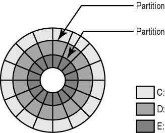 | One 4.3-GB physical drive with three partitions: C (1-GB primary drive) D (1.65-GB extended drive) E (1.65-GB extended drive) One physical drive and three logical drives |
How to Partition
The FDISK utility is used to partition a drive. After the drive is installed and the CMOS is updated, run FDISK to partition the drive(s).
Figure 8.13 shows the FDISK startup screen.
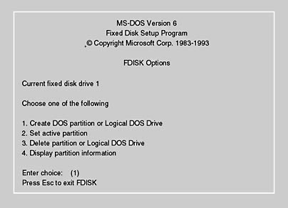
Figure 8.13 The FDISK startup screen.
The function of lines 1, 3, and 4 is clear. Line 2 sets the active partition. The active partition is the partition where the BIOS will look for an operating system when the computer is booted.
Don't confuse the primary partition with the active partition. On a computer with a single operating system, the primary and active partitions are usually the same. A computer with dual-boot capability might have separate partitions for each operating system. In that case, the active and primary partitions might not be the same.
The primary partition is where MS-DOS (or the Windows boot information) is stored on the hard disk drive, and the active partition is where the operating system is stored on the hard drive. (If MS-DOS is the only operating system, the primary partition and active partition are the same.) Other operating systems— Windows NT, Windows 2000, and OS/2, for instance—can exist on an extended partition.
Advanced operating systems can create a special partition called a boot partition. When the computer boots, a menu prompts the user to pick which operating system to use. The boot manager then sets the chosen partition as active, which starts the operating system located in that partition.
NOTE
MS-DOS has a limitation not shared by any other operating system: it must be placed on the primary partition, and that partition must always be named C. OS/2, UNIX, and Windows NT/2000 can boot from another drive letter, as well as from the C drive.
High-Level Formatting
The high-level format is simply called "format" (the program used to perform a high-level format is called FORMAT.COM). This is the same format command used to prepare floppy disk drives. The high-level format performs two major functions:
- It creates and configures the file allocation tables (FATs).
- It creates the root directory, which is the foundation upon which files and subdirectories are built.
File Allocation Tables (FATs)
The base storage unit for drives is a sector. Each sector can store between one byte and 512 bytes of data. Any file less than 512 bytes is stored in a single sector, and only one file can be assigned a sector. Therefore, any part of a sector left unfilled is wasted. When files are stored in more than one sector (if they are greater than 512 bytes), MS-DOS needs a way to keep track of each location and the order in which data is stored. MS-DOS also needs to know which sectors are full and which sectors are available for data, so it uses the file allocation table (FAT) to keep track of this information.
The FAT is simply an index that keeps track of which part of the file is stored in which sector. Each partition (or floppy disk) has two FATs stored near the beginning of the partition. These FATs are called FAT #1 and FAT #2. They are identical. Each FAT can be looked at as a two-column spreadsheet.
| Left Column | Right Column |
|---|---|
| Gives each sector a number (in hex) from 0000 to FFFF (65,536 sectors). The left side contains 16 bits (4 hex characters = 16 bits). This FAT is called a 16-bit FAT. Floppy disk drives use 12-bit FATs because they store substantially less data. | Contains information on the status of the sector. During formatting, any bad sectors are marked with a status code of FFF7 and good sectors are marked 0000. |
Sectors and Clusters
As mentioned, the CHS values limit the maximum size of a hard disk drive to 504 MB under the older PC operating systems. The 16-bit FAT can address 64,000 (2l6) locations. Therefore, the size of a hard drive partition should be limited to 64,000 x 512 bytes per sector or 32 MB. With this limitation, you might ask, how are larger hard drives possible?
There are two solutions to this problem. The first method, used with earlier drives (under 100 MB), was to use FDISK to break the drive up into multiple partitions, each less than 32 MB.
The second method is called clustering. Clustering means to combine a set of contiguous sectors and treat them as a single unit in the FAT. The number of sectors in each cluster is determined by the size of the partition. There can never be more than 64,000 clusters. To determine the number of sectors in a partition, divide the number of bytes in the partition by 512 (bytes per sector). Then divide the number of sectors by 64,000 (maximum allowable clusters). The following table provides an estimate of sectors per cluster.
| Partition (in MB) | Total Bytes | Total Sectors | Sectors per Cluster | Bytes per Cluster |
|---|---|---|---|---|
| 32 | 33,554,432 | 65,536 | 1 | 524 |
| 64 | 67,108,864 | 131,072 | 2 | 1049 |
| 128 | 134,217,728 | 262,144 | 4 | 2097 |
| 256 | 268,435,456 | 524,288 | 8 | 4194 |
| 512 | 536,870,912 | 1,048,576 | 16 | 8389 |
| 1000 | 1,048,576,000 | 2,048,000 | 32 | 16,384 |
| 2000 | 2,097,152,000 | 4,096,000 | 64 | 32,768 |
| 4000 | 4,194,304,000 | 8,192,000 | 128 | 65,536 |
NOTE
Remember: for this table, a sector is not the basic unit of storage—it is now the cluster.
How the File Allocation Table Works
When a file is saved:
- MS-DOS starts at the beginning of the FAT and looks for the first space marked "open for use" (0000). It begins to write to that cluster.
- If the entire file can be saved within that one cluster, the code FFFF (last cluster) is placed in the cluster's status field and the file name is added to the directory.
- The cluster number is placed with the file name.
- If the file takes more than one cluster, MS-DOS searches for the next open cluster and places the number of the next cluster in the status field. MS-DOS continues filling and adding clusters until the entire file is saved.
- The last cluster then receives the end of file code (FFFF).
FAT32
Windows 98 and Windows 95 (OSR2—the final version of Windows 95, available only on new machines, also called version C) support the new FAT32 file system. FAT32 can create partitions up to 2 terabytes (two trillion bytes) in size (much larger than the 2-GB limit of FAT16) and uses smaller clusters than FAT16. This results in a more efficient use of space on a large hard disk.
When deciding whether to use FAT32, take the following into consideration:
- Don't use FAT32 on any partition that other operating systems—except for Windows 95 OSR2—will use.
- MS-DOS, Windows 3.x, the original release of Windows 95, and Windows NT clients can read FAT32 partitions shared across a network.
- If you dual boot between Windows 98 and another operating system (such as Windows NT 4.x), the drive C partition cannot be FAT32.
- You cannot compress FAT32 partitions.
- Windows 98 MS-DOS mode fully supports FAT32, so you can run most MS-DOS-mode games and applications from FAT32 partitions.
- Some older applications written to FAT16 specification might not display disk space larger than 2 GB.
- Do not use any utilities that do not support FAT32. This could result in data loss and might corrupt the file system on the hard drive.
Fragmentation
Fragmentation is the scattering of parts of the same disk file over different areas of the disk.
During PC use, files are opened and then saved back to disk. As mention earlier, the file is often stored in several small sections. Fragmentation is caused by the following:
- As a file is written to sectors (clusters), it is placed in the first available location.
- The continual addition and deletion of files begins to leave open clusters.
- These open clusters are filled by the first part of the next file to be saved.
- Soon, files become fragmented, or scattered, all over the drive.
This is an acceptable way to operate and causes no problems for the computer itself. However, excessive fragmentation slows down the hard disk drive because it has to access two or more areas to retrieve a file. It is possible for a single file to be fragmented into hundreds of pieces, forcing the R/W heads to travel all over the hard disk drive.
Most operating systems have either native or third-party applications that will defragment a drive. These should be used on a regular basis to improve performance and save wear and tear on the drive.
Disk Compression Disk compression is offered as part of the Microsoft Plus add-on product for Windows 95, but is included in Windows 98 as the DriveSpace 3 program. It works by creating a single big file (called a compressed volume file or CVF) that acts like a virtual disk drive (with its own drive letter). Files you write to the CVF will become records within the one big file. This process is normally transparent to the user.
NOTE
Keep in mind that you cannot use DriveSpace 3 with partitions that use the FAT32 file system. If you wish to compress a drive under Windows 98, use the FAT16 file system when installing the drive.
Compression saves space in two ways. It:
- Eliminates the wasted cluster space used by separate disk files.
- Replaces sequences of identical values or characters in the file data with a special reference that represents the actual data, but occupies less disk space than the data itself would.
When the data is retrieved from the file, the real values are extracted from the special references. The result can be a dramatic reduction in the disk space occupied by files, especially with uncompressed graphics files and word-processing documents.
Using compression introduces some risk because an error in the compressed volume file can make data inaccessible. It is safest not to use a compressed file for critical data, and some older programs (particularly games) might not work with compression. With DriveSpace 3 you can use the Troubleshooter to identify and fix problems.
Compression is less necessary today, because of the advent of large hard disk drives and the availability of the FAT32 file system with its smaller cluster sizes.
The elimination of fragmentation improves the speed of the hard disk drive dramatically. Running a program to eliminate fragmentation is called defragmenting a drive. The slang term "defrag" is often used. MS-DOS installations include a defragmentation program called DEFRAG. Windows 95 and 98 include a defragmentation program that can be accessed from the Start menu—select Programs, then select Accessories, and finally select System Tools.
NOTE
DEFRAG cannot rewrite or move systems and hidden files. These files might be program files that are copy protected and must not be moved after the program is installed. System files such as the MS-DOS core program must occupy a particular position on the disk.
CAUTION
Never run a defragmentation program designed for MS-DOS or Windows 3.x on a Windows 95 or 98 system. The program might not understand the Windows 95 and 98 long file names, and data might be lost.
Maintaining a Disk Drive
Being prepared for a potential failure before a hard disk drive fails to work properly can save lost data and time. How fully you should prepare depends on the answers to two questions:
- Can you afford to lose the data in question?
- How much time do you have to start over?
With this in mind, to minimize the impact of a hard disk drive failure:
- Perform comprehensive, frequent backups.
- Save a copy of the boot-sector and partition-table information.
You should have the following tools at hand to perform hard disk repairs:
- A list of the hard disk drive's parameters and the correct CMOS settings required.
- A bootable floppy disk with the FDISK, FORMAT, CHKDSK, and MSCDEX (if using a CD-ROM) command files. Adding EDIT or another text editor is handy for tweaking the CONFIG.SYS and AUTOEXEC.BAT files.
- Drivers needed to get the operating system running with any primary expansion cards (drive controllers, SCSI card, display adapter, and so on.)
- Good cables for the kinds of drives you might have to repair.
- CHKDSK or other hard disk inspection programs that are part of the operating system on the drive in question. Be sure to use the right version!
A number of third-party programs are also available for use with older hardware and operating systems. These programs are available at most computer software stores.
CAUTION
When using any third-party programs to troubleshoot/repair a drive, be sure they are certified for the hard disk drive and operating system in question. Use uncertified third-party programs only when such a step is the last resort before discarding the drive. Even then, be aware that the program may cause problems of its own. Keep the software up to date; changes in the operating system or bugs found in the utility can render the product more of a problem than a cure. If possible, back up any critical data before using the software.
Abort, Retry, Fail or Abort, Retry, Fail, Ignore Errors
The most common drive errors begin with "Abort, Retry, Fail," or "Abort, Retry, Fail, Ignore."
When you see any of the following errors, you have a drive problem:
Sector not found reading drive C: Abort, Retry, Fail? Data error reading drive C: Abort, Retry, Fail, Ignore? Read fault reading drive C: Abort, Retry, Fail, Ignore? Invalid media type reading drive C: Abort, Retry, Fail? |
These errors are the easiest to fix and can usually be attributed to a bad sector on the drive. When this happens, try the following.
ScanDisk
MS-DOS, Windows 3.x, and Windows 95 and 98 contain versions of the ScanDisk program. ScanDisk performs a battery of tests on a hard disk, including looking for invalid file names, invalid file dates and times, bad sectors, and invalid compression structures. In the file system, ScanDisk looks for lost clusters, invalid clusters, and cross-linked clusters. Regular use of ScanDisk can help prevent problems as well as resolve them. Windows 95- and 98-based computers will automatically run ScanDisk any time the operating system is improperly shut down—that is, when the power is turned off before the system is allowed to complete its shutdown procedures.
Verify the Media
Most SCSI drives have a program built into the controller that will verify the hard disk drive and make repairs if a sector has become unusable or unstable. Boot the PC and watch for a prompt to enter the SCSI BIOS setup (usually CTRL+A). Then choose Disk Utilities and the option to verify or inspect the drive. Do not select the low-level format option. After the program is finished, reboot the computer and see if the problem is resolved. If the disk fails verification, it might need to undergo low-level formatting or be replaced.
CMOS Errors
At times, the system CMOS becomes unstable. This can result in the following error messages:
CMOS configuration mismatch No boot device available Drive not found Missing operating system |
Checking the CMOS is quick and easy. It is a good idea to always have a backup of the CMOS data on paper.
NOTE
After boot up, if you receive the message "Strike F1 key to continue," this indicates that your system configuration is invalid and you will need to check the CMOS settings.
Connectivity Errors
Connectivity problems (when something is not connected or plugged in) usually appear when you boot up a computer. Look for the following messages:
HDD Controller failure No boot device available Drive not found |
Connectivity errors are overcome by inspecting the entire connection system (including power). You might want to try removing and reseating the controller if you get an HDD controller failure.
TIP
As a computer technician, you should keep an extra controller and cables around. Often, substituting a good cable or controller is the quickest way to solve a hard disk drive problem.
Lost Boot and Partition Information
It is possible for a drive to lose partition information. Look for these errors:
Invalid partition table Corrupt boot sector Non-system disk or disk error |
Boot and partition information is stored on sectors and can fail. If the partition table or boot sector is corrupted, the best solution is to restore the data on the drive from a backup copy after repartitioning the drive and reloading the operating system.
Lesson Summary
The following points summarize the main elements of this lesson:
- The maximum storage capacity of a hard disk drive is determined by its geometry.
- CHS values define the geometry of a hard disk drive.
- The largest hard disk drive recognized by the BIOS will vary with the age of the system.
- Proper CMOS settings are required for hard disk drives.
- There are two types of partitions—primary and extended.
- A cluster is the basic unit of storage.
- The FDISK program is used to partition drives.
- Microsoft ScanDisk is a useful tool for diagnosing and repairing many disk problems.
- The proper drive information must be held in CMOS for proper drive operation.
EAN: N/A
Pages: 127