| In this scenario, you configure QoS on both Catalyst CatOS-based switches and Cisco IOS-based switches. Rather than present a series of scenarios that configure specific QoS features, this chapter presents a single, longer scenario that shows you how to configure QoS throughout the LAN environment. Scenario Exercise Figure 9-6 illustrates the topology used for this scenario. Corporation XYZ has recently implemented a pilot Cisco Architecture for Voice, Video, and Integrated Data (AVVID) IP Telephony network to replace the legacy PBX system. Initially, Corporation XYZ pilots the Cisco IOS IP Telephony Service software, before introducing a Cisco CallManager platform. To ensure that voice functionality operates with the same quality and reliability in both solutions, you must configure quality of service. The configuration of QoS ensures voice traffic receives the appropriate bandwidth and latency characteristics. The Corporation XYZ network includes an intranet web server that at certain times has caused LAN congestion. Corporation XYZ would like the capability to rate limit web traffic to a maximum rate if required. You must ensure all of the quality of service requirements mentioned are met by the LAN switches. Figure 9-6. Scenario 9-1 Topology 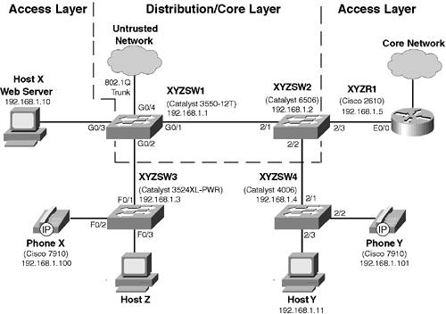
The LAN consists of an access layer that is used to provide network access for devices such as IP telephones. A combined distribution/core layer provides connectivity for the access switches to core network services and applications. The following describes the function of each component of the scenario topology shown in Figure 9-6: XYZSW1 is a Catalyst 3550-12T access/distribution switch that provides connectivity for the XYZSW3 switch. XYZSW1 interconnects with XYZSW2, the other distribution switch, via an 802.1Q trunk. XYZSW1 also provides access layer functions by connecting directly to Host X. XYZSW2 is a Catalyst 6506 access/distribution switch that provides access for the XYZSW4 switch. XYZSW2 interconnects with XYZSW1, the other distribution switch, via an 802.1Q trunk. XYZSW2 also provides access layer functions by connecting directly to XYZR1. XYZSW3 is a Catalyst 3524XL-PWR switch that provides access for Cisco IP telephones. This is a common access switch used in IP Telephony deployments, because it provides inline power for Cisco IP telephones.
NOTE The Catalyst 3550 switch family now includes a 24-port switch that provides inline power. In the future, a Catalyst 3750 switch will be produced that offers inline power based upon the IEEE 802.3af standard.
The Catalyst 3550 switch family now includes a 24-port switch that provides inline power. In the future, a Catalyst 3750 switch will be produced that offers inline power based upon the IEEE 802.3af standard. XYZSW4 is a Catalyst 4006 switch that also provides network access for Cisco IP telephones. This is also a common workgroup/departmental access switch used in IP Telephony deployments, because an inline power module is available for the Catalyst 4000 series switches. XYZR1 is a Cisco 2610 router that runs the Cisco IOS IP Telephony service. Phone X and Phone Y are Cisco 7910 IP Telephones. Host X is an intranet server that uses Microsoft NetMeeting to stream audio to web clients. Host Y is a web client that connects to Host X for Intranet web access.
Scenario Objectives The scenario objectives are as follows: Configure Catalyst 2900XL/3500XL QoS features Configure Catalyst 2950/3550 QoS features Configure Catalyst 2980/4000 QoS features Configure Catalyst 6000/6500 QoS features Configure the Cisco IOS IP Telephony Service to support Cisco IP Phones Establish a phone call over an IP network
Equipment Needed The equipment needed is a follows: One CatOS Catalyst 6000/6500 Switch with Supervisor 2 installed or Supervisor 1/1a with policy feature card installed. One Cisco IOS Catalyst 3550-12T or 3550-12G switch. One Cisco IOS Catalyst 4003 or 4006 switch. One Cisco IOS Catalyst 3524PWR-XL inline power switch. One Cisco 2610 Router running a 12.2(2)XB image (or higher) with an IP Plus feature set. Two Cisco 7910, 7940, or 7960 IP Phones. Two PCs running a Windows operating system with network card installed and configured to use TCP/IP. To verify some QoS configurations, Host X requires a web server and File Transfer Protocol (FTP) server running.
Scenario Planning The first goal of this scenario is to show you how to configure QoS on Cisco Catalyst switches. The second, and more important, goal is to make you aware of the need for end-to-end QOS. This scenario shows you how to implement end-to-end QoS on a LAN, but you should understand that in the real world a QoS implementation must include the devices of the wide-area network as well. In fact, it is in the wide-area network that QoS is the most critical. When you are planning for end-to-end QoS, you should create a table that lists each of the various QoS markings and the level of QoS they represent on the network. Table 9-5 shows the QoS markings used in this scenario. Table 9-5. QoS Markings Used in Scenario 9-1Type | Marking | Description |
|---|
CoS | 0 | Low priority traffic | 1 | Internal company traffic | 3 | Business critical traffic | 5 | VoIP control traffic | DSCP | 0 | Low priority traffic | 8 | Internal company traffic | 24 | Business critical traffic | 41 | VoIP traffic | 46 | VoIP traffic (EF) |
As you can see in Table 9-5, traffic is represented in both CoS and DSCP markings. CoS is required for non-DSCP aware switches, which include XYZSW3 (Catalyst 3500XL) and XYZSW4 (Catalyst 4000). It is also a good idea to define key traffic flows on your network, so that you can determine where QoS needs to be applied. Figure 9-7 shows the Scenario 9-1 network with each of the traffic types shown in Table 9-5. Figure 9-7. Scenario 9-1 Traffic Types 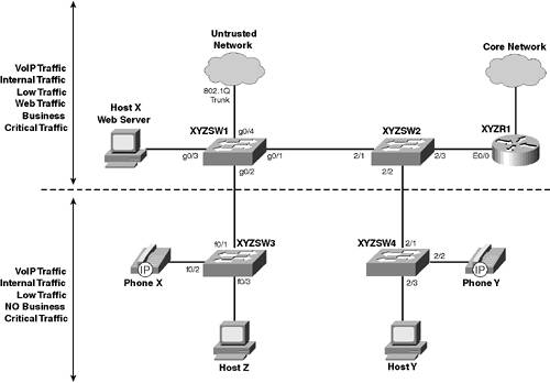
In Figure 9-7, you can see that business critical traffic is transmitted only between devices connected to XYZSW1 and XYZSW2, and not to devices connected to XYZSW3 or XYZSW4. Therefore, no business critical traffic tagged with a CoS of 3 is being sent or received from these switches. This is important to understand, as you can then assign a DSCP value of 46 (voice traffic) to all traffic with a CoS of 5 from XYZSW3 and XYZSW4. In this scenario, you configure XYZSW3 and XYZSW4 to tag only voice with a CoS of 5, so no other traffic should be tagged with this CoS. Command Syntax The requirements for configuring QoS vary immensely for each platform, and providing command syntax for all of these commands would require a significant section, which would only serve to bore you. If you need command syntax help for any of the commands, visit the Cisco documentation web site at www.cisco.com/univercd/home/home.htm. Configuration Tasks In this scenario, you perform the following tasks: Step 1 Prepare the network Step 2 Configure the IOS IP Telephony service Step 3 Configure QoS at the access layer Step 4 Configure QoS at the distribution layer
Step 1Preparing the Network In this step, you perform the following to prepare the network: - Configure basic parameters on each switch
- Interconnect each switch
- Connect the router, host, and IP Phones
- Configure basic parameters on XYZR1
Configuring Basic Parameters on Each Switch Before beginning, ensure you have a working console connection on a PC running terminal emulation software and then confirm you can access each switch via the console port. Step 1. | On XYZSW1, configure system name, disable Domain Name System (DNS) name resolution, add a Telnet/enable password of cisco, an IP address of 192.168.1.1/24, and a default gateway of 192.168.1.5 (XYZR1), as shown in Example 9-1.
Example 9-1. Configuring Basic Parameters on XYZSW1 Switch> enable Password: Switch# configure terminal Switch(config)# hostname XYZSW1 XYZSW1(config)# no ip domain-lookup XYZSW1(config)# enable secret cisco XYZSW1(config)# line vty 0 4 XYZSW1(config-line)# password cisco XYZSW1(config-line)# interface VLAN1 XYZSW1(config-if)# no shutdown XYZSW1(config-if)# ip address 192.168.1.1 255.255.255.0 XYZSW1(config-if)# exit XYZSW1(config)# ip default-gateway 192.168.1.5 XYZSW1(config)# end
| Step 2. | On XYZSW2, configure the system name, a Telnet/enable password of cisco, an IP address of 192.168.1.2/24, and a default gateway of 192.168.1.5 (XYZR1), as shown in Example 9-2.
Example 9-2. Configuring Basic Parameters on XYZSW2 Console enable Enter password: Console (enable) set system name XYZSW2 System name set. XYZSW2> (enable) set password Enter old password: Enter new password: ***** Retype new password: ***** Password changed. XYZSW2> (enable) set enablepass Enter old password: Enter new password: ***** Retype new password: ***** Password changed. XYZSW2> (enable) set interface sc0 192.168.1.2 255.255.255.0 XYZSW2> (enable) set ip route default 192.168.1.5 Route added.
| Step 3. | On XYZSW3, configure the system name, add a Telnet/enable password of "cisco," disable DNS name resolution, an IP address of 192.168.1.3/24, and a default gateway of 192.168.1.5 (XYZR1), as shown in Example 9-3.
Example 9-3. Configuring Basic Parameters on XYZSW3 Switch> enable Password: Switch# configure terminal Switch(config)# hostname XYZSW3 XYZSW3(config)# no ip domain-lookup XYZSW3(config)# enable secret cisco XYZSW3(config)# line vty 0 4 XYZSW3(config-line)# password cisco XYZSW3(config-line)# interface VLAN1 XYZSW3(config-if)# no shutdown XYZSW3(config-if)# ip address 192.168.1.3 255.255.255.0 XYZSW3(config-if)# exit XYZSW3(config)# ip default-gateway 192.168.1.5 XYZSW3(config)# end
| Step 4. | On XYZSW4, configure the system name, add a Telnet/enable password of "cisco," an IP address of 192.168.1.4/24, and a default gateway of 192.168.1.5 (XYZR1), as shown in Example 9-4.
Example 9-4. Configuring Basic Parameters on XYZSW4 Console enable Enter password: Console (enable) set system name XYZSW4 System name set. XYZSW4> (enable) set password Enter old password: Enter new password: ***** Retype new password: ***** Password changed. XYZSW4> (enable) set enablepass Enter old password: Enter new password: ***** Retype new password: ***** Password changed. XYZSW4> (enable) set interface sc0 192.168.1.4 255.255.255.0 XYZSW4> (enable) set ip route default 192.168.1.5 Route added.
|
Interconnecting the Switches For this scenario, you interconnect all switches using crossover UTP cables between Fast Ethernet 802.1Q trunk ports (you can use gigabit Ethernet trunks if you have these). Step 1. | On XYZSW1, configure 100 Mbps speed and full duplex on ports GigabitEthernet0/13 and enable trunking using 802.1Q, as shown in Example 9-5.
Example 9-5. Configuring Trunks on XYZSW1 XYZSW1# configure terminal XYZSW1(config)# interface GigabitEthernet0/1 XYZSW1(config-if)# description TRUNK TO XYZSW2 XYZSW1(config-if)# no shutdown XYZSW1(config-if)# speed 100 XYZSW1(config-if)# duplex full XYZSW1(config-if)# switchport trunk encapsulation dot1q XYZSW1(config-if)# switchport mode trunk XYZSW1(config-if)# interface GigabitEthernet0/2 XYZSW1(config-if)# description TRUNK TO XYZSW3 XYZSW1(config-if)# no shutdown XYZSW1(config-if)# speed 100 XYZSW1(config-if)# duplex full XYZSW1(config-if)# switchport trunk encapsulation dot1q XYZSW1(config-if)# switchport mode trunk XYZSW1(config-if)# exit XYZSW1(config)# interface GigabitEthernet0/3 XYZSW1(config-if)# description TRUNK TO UNTRUSTED NETWORK XYZSW1(config-if)# no shutdown XYZSW1(config-if)# speed 100 XYZSW1(config-if)# duplex full XYZSW1(config-if)# switchport trunk encapsulation dot1q XYZSW1(config-if)# switchport mode trunk XYZSW1(config-if)# end
NOTE In this scenario, GigabitEthernet0/4 is not connected to anything, but for the purposes of the scenario, assume some network is connected for GigabitEthernet0/4. | Step 2. | On XYZSW2, configure 100 Mbps speed and full duplex on port 2/1 and port 2/2 and enable trunking using 802.1Q, as show in Example 9-6.
Example 9-6. Configuring Trunks on XYZSW2 XYZSW2> (enable) set port speed 2/1-2 100 Port(s) 2/1-2 transmission speed set to 100Mbps. XYZSW2> (enable) set port duplex 2/1-2 full Port(s) 2/1-2 to full-duplex. XYZSW2> (enable) set trunk 2/1 on dot1q Port(s) 2/1 trunk mode set to on. Port(s) 2/1 trunk type set to dot1q. XYZSW2> (enable) set trunk 2/2 on dot1q Port(s) 2/2 trunk mode set to on. Port(s) 2/2 trunk type set to dot1q.
| Step 3. | On XYZSW3, configure 100 Mbps speed and full duplex on port fastEthernet0/1 and enable trunking using 802.1Q, as shown in Example 9-7.
Example 9-7. Configuring Trunks on XYZSW3 XYZSW3# configure terminal XYZSW3(config)# interface fastEthernet0/1 XYZSW3(config-if)# description TRUNK TO XYZSW1 XYZSW3(config-if)# no shutdown XYZSW3(config-if)# speed 100 XYZSW3(config-if)# duplex full XYZSW3(config-if)# switchport trunk encapsulation dot1q XYZSW3(config-if)# switchport mode trunk XYZSW3(config-if)# end
| Step 4. | On XYZSW4, configure 100 Mbps speed and full duplex on port 2/1 and enable trunking using 802.1Q, as shown in Example 9-8.
Example 9-8. Configuring Trunks on XYZSW4 XYZSW4> (enable) set port speed 2/1 100 Port 2/1 transmission speed set to 100Mbps. XYZSW4> (enable) set port duplex 2/1 full Port 2/1 to full-duplex. XYZSW4> (enable) set trunk 2/1 on dot1q Port(s) 2/1 trunk mode set to on. Port(s) 2/1 trunk type set to dot1q.
|
Once these configurations are complete, wait for at least 30 seconds to allow the spanning-tree state of the trunk ports to progress from the learning  listening forwarding state. listening forwarding state. Step 5. | Verify that you are able to ping all other switches from any switch in the network, as shown in Example 9-9.
Example 9-9. Verifying Ping connectivity XYZSW2> (enable) ping 192.168.1.1 !!!!! XYZSW2> (enable) ping 192.168.1.3 !!!!!
|
Connecting the Router, Host, and IP Phones Connect each end device to the appropriate switch and port and prepare each port for the devices. Step 1. | On XYZSW1, configure 100 Mbps speed, full duplex for port GigabitEthernet0/3 and configure the port as an access port, as shown in Example 9-10.
Example 9-10. Configuring Ports on XYZSW1 XYZSW1# configure terminal XYZSW1(config)# interface GigabitEthernet0/3 XYZSW1(config-if)# no shutdown XYZSW1(config-if)# speed 100 XYZSW1(config-if)# duplex full XYZSW1(config-if)# switchport mode access XYZSW1(config-if)# end
| Step 2. | On XYZSW2, configure 10 Mbps speed, half duplex for port 2/3 (connected to XYZR1) and configure the port as an access port, as shown in Example 9-11.
Example 9-11. Configuring Ports on XYZSW2 XYZSW2> (enable) set port speed 2/3 10 Port 2/3 transmission speed set to 10Mbps. XYZSW2> (enable) set port duplex 2/3 half Port 2/3 to half-duplex.
| Step 3. | On XYZSW3, configure port fa0/2 to autosense, configure the port as an access port, and ensure inline power is enabled (if you want to use this feature). Also, configure port fastEthernet0/3 as an 802.1Q trunk, as shown in Example 9-12.
Example 9-12. Configuring Ports on XYZSW3 XYZSW3# configure terminal XYZSW3(config)# interface fastEthernet0/2 XYZSW3(config-if)# description PHONE X XYZSW3(config-if)# no shutdown XYZSW3(config-if)# speed auto XYZSW3(config-if)# duplex auto XYZSW3(config-if)# switchport mode access XYZSW3(config-if)# power inline auto XYZSW3(config-if)# exit XYZSW3(config)# interface fastEthernet0/3 XYZSW3(config-if)# description TRUNK TO HOST Z XYZSW3(config-if)# no shutdown XYZSW3(config-if)# speed 100 XYZSW3(config-if)# duplex full XYZSW3(config-if)# switchport trunk encapsulation dot1q XYZSW3(config-if)# switchport mode trunk XYZSW3(config-if)# end
TIP When connecting Cisco IP Phones, configure the switch port as autosensing. Do not hard code the port speed and duplex settings, because the phone must negotiate these settings. | Step 4. | On XYZSW4, configure port 2/2 to autosense and hard code port 2/3 to 100 Mbps, full duplex, as shown in Example 9-13.
Example 9-13. Configuring Ports on XYZSW4 XYZSW4> (enable) set port speed 2/2 auto Port 2/2 transmission speed set to auto. XYZSW2> (enable) set port duplex 2/2 auto Port 2/2 to auto. XYZSW2> (enable) set port speed 2/3 100 Port 2/3 transmission speed set to 100Mbps. XYZSW2> (enable) set port duplex 2/3 full Port 2/3 to full-duplex.
| Step 5. | Verify that you can ping from Host X to Host Y, as shown in Example 9-14.
Example 9-14. Verifying End-to-End Connectivity C:\WINXP\system32>ping 192.168.1.11 Pinging 192.168.1.11 with 32 bytes of data: Reply from 192.168.1.11: bytes=32 time=1ms TTL=255 Reply from 192.168.1.11: bytes=32 time=1ms TTL=255 Reply from 192.168.1.11: bytes=32 time=1ms TTL=255 Reply from 192.168.1.11: bytes=32 time=1ms TTL=255 Ping statistics for 192.168.1.11: Packets: Sent = 4, Received = 4, Lost = 0 (0% loss), Approximate round trip times in milli-seconds: Minimum = 1ms, Maximum = 1ms, Average = 1ms
|
Configuring Basic Parameters on XYZR1 Do the following to configuring basic parameters on XYZR1: Step 1. | On XYZR1, configure host name, Telnet/enable passwords of "cisco," IP addressing, and the correct date and time, as shown in Example 9-15.
Example 9-15. Configuring XYZR1 Router> enable Router# configure terminal Router(config)# hostname XYZR1 XYZR1(config)# enable secret cisco XYZR1(config)# clock timezone NZT 12 XYZR1(config)# line vty 0 4 XYZR1(config-line)# password cisco XYZR1(config-line)# interface ethernet0/0 XYZR1(config-if)# no shutdown XYZR1(config-if)# ip address 192.168.1.5 255.255.255.0 XYZR1(config)# exit XYZR1# clock set 12:00:00 23 March 2002
| Step 2. | On XYZR1, verify you can ping all switches in the network, as shown in Example 9-16.
Example 9-16. Verifying XYZR1 Connectivity XYZR1#ping 192.168.1.1 Type escape sequence to abort. Sending 5, 100-byte ICMP Echos to 192.168.1.1, timeout is 2 seconds: !!!!! Success rate is 100 percent (5/5), round-trip min/avg/max = 4/8/12 ms XYZR1#ping 192.168.1.2 Type escape sequence to abort. Sending 5, 100-byte ICMP Echos to 192.168.1.1, timeout is 2 seconds: !!!!! Success rate is 100 percent (5/5), round-trip min/avg/max = 4/8/12 ms ...
|
Step 2Configuring the IOS IP Telephony Service In this step, you perform the following on XYZR1: - Configure DHCP server support
- Configure the IOS IP Telephony service
- Configure IP Phone support
WARNING The IP Plus feature set on the Cisco 2600 series router supports the IP Telephony service features detailed in this section out of the box. However, you must license the use of this feature by purchasing a separate license from Cisco. You also require a Cisco login to download IP Phone images from Cisco.
Configuring DHCP Server Support Configuring DHCP server support is done as follows: Step 1. | Configure a DHCP exclusion range that prevents XYZR1 from providing DHCP addresses within the reserved range of 192.l68.1.1-192.168.1.99, as shown in Example 9-17.
Example 9-17. Creating a DHCP Exclusion Range on XYZR1 XYZR1# configure terminal XYZR1(config)# ip dhcp excluded-address 192.168.1.1 192.168.1.99
| Step 2. | Configure the DHCP server on XYZR1, creating a DHCP address pool for the 192.168.1.0/24 subnet, ensuring the TFTP Server option (option 150) is set to the IP address of XYZR1, as shown in Example 9-18.
Example 9-18. Creating a DHCP Pool on XYZR1 XYZR1(config)# ip dhcp pool QOSLAB XYZR1(dhcp-config)# network 192.168.1.0 255.255.255.0 XYZR1(dhcp-config)# option 150 ip 192.168.1.5 XYZR1(dhcp-config)# default-router 192.168.1.5 XYZR1(dhcp-config)# end
|
In Example 9-18, you first configure the DHCP server to exclude the address range 192.168.1.1 through 192.168.1.99 from the DHCP scope. Then, in Example 9-18, you create a DHCP scope called QOSLAB, which provides DHCP address leases for the 192.168.1.0/24 subnet. You configure the TFTP Server option (option 150) with the IP address of XYZR1, because this is required for the phones to download their firmware image from XYZR1 when they boot up. The address leases provided start from 192.168.1.100 (not 192.168.1.1) because of the exclusion range configured in Example 9-17. Configuring the IP Telephony Service Do the following to configure the IP telephony service: Step 1. | Configure basic IP Telephony service parameters, as shown in Example 9-19.
Example 9-19. Configuring the XYZR1 Keyswitch XYZR1# configure terminal XYZR1(config)# telephony-service XYZR1(config-telephony)# ip source-address 192.168.1.5 XYZR1(config-telephony)# load 7910 P004G302 XYZR1(config-telephony)# max-ephones 24 XYZR1(config-telephony)# max-dn 48 XYZR1(config-telephony)# dialplan-pattern 1 508339.... extension-length 4 XYZR1(config-telephony)# end
|
In Example 9-19, you enter telephony configuration mode and then first configure the IP address that the telephony service binds to. You must also configure the phone load that each phone model (e.g., 7910, 7940) should use by configuring the load command. Next, you specify the maximum number of phones allowed (max-ephones 24), the maximum number of directory numbers/extensions allowed (max-dn 48), and also an expansion dial pattern that is appended to all outgoing calls in calling ID information (dial-plan pattern). Step 2. | Using the show flash command, verify that your Flash file system contains the appropriate phone load files (.bin files) and that the initial keyswitch configuration has created a SEPDEFAULT.cnf file, as shown in Example 9-20.
Example 9-20. Verifying the Appropriate Files Are Present on XYZR1 XYZR1# show flash System flash directory: File Length Name/status 1 12273948 c2600-is-mz.122-2.XB.bin 2 14 SEPDEFAULT.cnf 3 258360 P004G302.bin [12535980 bytes used, 4241236 available, 16777216 total] 16384K bytes of processor board System flash (Read/Write)
|
In Example 9-20, the P004G302.bin file represents a phone load file, while the SEPDEFAULT.cnf file contains global configuration information for each phone. Step 3. | Configure XYZR1 as a TFTP server, enabling phones to download the appropriate phone files (SEPDEFAULT.cnf and any phone load files) stored in Flash, as shown in Example 9-21.
Example 9-21. Configuring TFTP Server Support on XYZR1 XYZR1# configure terminal Enter configuration commands, one per line. End with CNTL/Z. XYZR1(config)# tftp-server flash:SEPDEFAULT.cnf XYZR1(config)# tftp-server flash:P004G302.bin XYZR1(config)# end
|
Configuring the IP Phones Do the following to configure the IP phones: TIP A directory number tag is not the directory (extension) number itself, just an identifier for the directory number. You configure the directory extension number in the next step.
Step 1. | Configure the extension numbers and a display name for each of the directory number (DN) tags, as shown in Example 9-22.
Example 9-22. Configuring Directory Numbers XYZR1# configure terminal Enter configuration commands, one per line. End with CNTL/Z. XYZR1(config)#ephone-dn 1 XYZR1(config-ephone-dn)#number 4001 XYZR1(config-ephone-dn)#name PHONE X XYZR1(config-ephone-dn)#exit XYZR1(config)#ephone-dn 2 XYZR1(config-ephone-dn)#number 4002 XYZR1(config-ephone-dn)#name PHONE Y XYZR1(config-ephone-dn)#end
|
In Example 9-22, you assign the extension number 4001 and the display name of PHONE X to the DN tag of 1 and the extension number 4002 with a display name of PHONE Y to the DN tag 2. Step 2. | Configure phone support by creating a definition for each IP Phone that defines the MAC address of the phone and the directory number tag assigned to each button on the phone, as shown in Example 9-23 (every Cisco IP Phone is labeled with its MAC address).
Example 9-23. Configuring IP Phones XYZR1# configure terminal Enter configuration commands, one per line. End with CNTL/Z. XYZR1(config)#ephone 1 XYZR1(config-ephone)#mac-address 0007.0ea6.398d XYZR1(config-ephone)#button 1:1 XYZR1(config-ephone)#exit XYZR1(config)#ephone 2 XYZR1(config-ephone)#mac-address 0007.0ea6.33da XYZR1(config-ephone)#button 1:2 XYZR1(config-ephone)#end
|
In Example 9-23, you create a definition for each phone (for example, ephone 1) that includes the MAC address of each phone (mac-address xxxx.xxxx.xxxx) and the directory number (DN) tag associated with each button on the phone (button x:x). For example, the command button 1:2 assigns the DN tag 2 to button 1 on the phone. Step 3. | Ensure your IP Phones are connected to the correct ports on each switch. The phones should eventually receive an IP address via DHCP and register with XYZR1. Phone X should receive an extension number of 4001, while Phone Y should receive an extension number of 4002. You should be able to make calls between Phone X and Phone Y.
|
Step 3Configuring QoS at the Access Layer In this step, you configure QoS functions at the edge of the network, the access layer switches. XYZSW3 and XYZSW4 are dedicated access layer switches, so you configure these switches in this section. XYZSW1 and XYZSW2 provide both access layer and distribution layer connectivity; you configure the access layer features on XYZSW1 and XYZSW2. You now perform the following: - Configure access layer QoS on XYZSW3 and XYZSW4
- Configure access layer QoS on XYZSW1
- Configure access layer QoS on XYZSW2
Configuring Access Layer QoS on XYZSW3 and XYZSW4 XYZSW3 and XYZSW4 offer the most limited QoS features of the switches in the scenario and are the simplest to configure. In this section, you configure the following: Configure XYZSW3 to tag all voice frames from Phone X with a CoS of 5. You configure Phone X to tag any frames received from a PC connected to the phone with a CoS of 1. You then configure XYZSW3 to override the CoS on all frames received from Host Z, tagging each frame with a CoS of 0. Configure XYZSW4 to tag all frames from Phone Y with a CoS of 5. You configure the default CoS for frames from Host Y to be set to 1, which is applied to all frames because Host Y sends untagged frames. You then assign traffic with a CoS value of 5 to the strict priority queue on XYZSW4.
On the queuing and scheduling side, both XYZSW3 and XYZSW4 offer only a single priority queue and a normal queue on an egress port. The placement of frames into each queue is determined by the CoS of the frame; hence, it is important to classify frames correctly to ensure the correct placement of high priority traffic into the priority queue. Step 1. | Configure XYZSW3 to identify voice traffic on port fastEthernet0/2 and instruct Phone X to tag voice traffic with an 802.1p priority of 5 using the native VLAN. Also configure Phone X so that it sets the CoS to 1 for all untagged frames received from the PC by the phone. This means any data frames from a PC connected to Phone X (the 7940/7960 phones support connecting your PC directly to the phone, saving switch port capacity) are tagged with an 802.1p value of 1. Example 9-24 demonstrates the configuration required.
Example 9-24. Enabling Voice Prioritization over Data on the Same VLAN XYZSW3# configure terminal XYZSW3(config)# interface fastEthernet0/2 XYZSW3(config-if)# switchport voice vlan dot1p XYZSW3(config-if)# switchport priority extend cos 1 XYZSW3(config-if)#end
| Step 2. | Verify the voice VLAN configuration, as shown in Example 9-25.
Example 9-25. Verifying Voice VLAN Configuration XYZSW3#show interface fastEthernet0/2 switchport Name: Fa0/2 Switchport: Enabled Administrative mode: trunk Operational Mode: trunk Administrative Trunking Encapsulation: dot1q Operational Trunking Encapsulation: dot1q Negotiation of Trunking: Disabled Access Mode VLAN: 0 ((Inactive)) Trunking Native Mode VLAN: 1 (default) Trunking VLANs Enabled: ALL Trunking VLANs Active: 1 Pruning VLANs Enabled: 2-1001 Priority for untagged frames: 0 Override vlan tag priority: FALSE Voice VLAN: dot1p Appliance trust: extend cos 1
|
As you can see from Example 9-25, the voice VLAN configuration is dot1p (i.e., use a single VLAN for voice and data and tag the voice traffic with a CoS of 5) and the appliance trust is set to override the 802.1p value of all PC data frames to 1. Step 3. | You also want to ensure traffic from Host Z has a CoS set to 0, because this host supports 802.1p tagging, and you do not want traffic from Host Z to affect the quality of service provided to voice within your network. Configure XYZSW3 to override the 802.1p priority of any tagged frames arriving on port fastEthernet0/3 to a value of 0, as shown in Example 9-26.
Example 9-26. Enabling 802.1p Priority Override on Port fa0/3 of XYZSW3 XYZSW3# configure terminal XYZSW3(config)# interface fastEthernet0/3 XYZSW3(config-if)# switchport priority default 0 XYZSW3(config-if)# switchport priority override XYZSW3(config-if)#end
| Step 4. | Verify the 802.1p priority configuration on fastEthernet0/3, as shown in Example 9-27.
Example 9-27. Verifying Voice VLAN Configuration XYZSW3# show interface fastEthernet0/3 switchport Name: Fa0/3 Switchport: Enabled Administrative mode: trunk Operational Mode: trunk Administrative Trunking Encapsulation: dot1q Operational Trunking Encapsulation: dot1q Negotiation of Trunking: Disabled Access Mode VLAN: 0 ((Inactive)) Trunking Native Mode VLAN: 1 (default) Trunking VLANs Enabled: ALL Trunking VLANs Active: 1 Pruning VLANs Enabled: 2-1001 Priority for untagged frames: 0 Override vlan tag priority: TRUE Voice VLAN: none Appliance trust: none
|
Example 9-27 shows that the switch is set to override the VLAN tag priority with the default priority of untagged frames, which is 0. Step 5. | Enable qualify of service features on XYZSW4, as shown in Example 9-28.
Example 9-28. Enabling QoS on XYZSW4 XYZSW4> (enable) set qos enable QoS is enabled.
| Step 6. | On XYZSW4, configure the default CoS value for any untagged frames received by the switch to 1, as shown in Example 9-29.
Example 9-29. Setting the Default CoS on XYZSW4 XYZSW4> (enable) set qos defaultcos 1 qos defaultcos set to 1
| Step 7. | On XYZSW4, determine the number of egress queues and thresholds available on port 2/1 (the uplink to XYZSW2) by using the show port capabilities command, as shown in Example 9-30.
Example 9-30. Determining QoS Port Capabilities on XYZSW4 XYZSW4> (enable) show port capabilities 2/1 Model WS-X4148 Port 2/1 Type 10/100BaseTX Speed auto,10,100 Duplex half,full Trunk encap type 802.1Q Trunk mode on,off,desirable,auto,nonegotiate Channel 2/1-48 Flow control no Security yes Dot1x yes Membership static,dynamic Fast start yes QOS scheduling rx-(none),tx-(2q1t) CoS rewrite no ToS rewrite no Rewrite no ...
|
Example 9-30 shows that the port has no QoS scheduling capabilities on the ingress (rx) side, but has two queues, each with a single drop threshold on the egress side. Step 8. | On XYZSW4, configure only traffic with a CoS of 5 (voice traffic) to be placed in queue 2 as shown in Example 9-31.
Example 9-31. Configuring Queuing on XYZSW4 XYZSW4> (enable) set qos map 2q1t 2 1 cos 5 Qos tx priority queue and threshold mapped to cos successfully.
|
The configuration in Example 9-31 places any traffic with a CoS of 5 into queue 2. Queue 2 is the strict priority queue that is always serviced over queue 1. Step 9. | Verify the queuing configuration on XYZSW4 by using the show qos info command, as shown in Example 9-32.
Example 9-32. Verifying Queuing on XYZSW4 XYZSW4> (enable) show qos info config QoS is enabled All ports have 2 transmit queues with 1 drop thresholds (2q1t). Default CoS = 1 Queue and Threshold Mapping: Queue Threshold CoS ----- --------- --------------- 1 1 0 1 2 3 4 6 7 2 1 5
|
Example 9-32 shows that the default CoS has been set to 1, and only traffic with a CoS of 5 is transmitted out the priority queue (queue 2). Configuring Access Layer QoS on XYZSW1 XYZSW1 is a combined access/distribution layer that provides access layer connectivity for Host X, as well as a trunk connection to an untrusted network. In this section, you configure the QoS for the access layer port connected to Host X, classifying traffic (based upon access control lists) and rate limiting particular types of traffic received from Host X. You also configure QoS for the trunk port (port GigabitEthernet0/4), classifying and marking voice traffic received on the trunk, and applying an aggregate rate limit of 1 Mbps for all incoming traffic on the trunk. Step 1. | Globally enable the qualify of service features on XYZSW1, as shown in Example 9-33.
Example 9-33. Enabling QoS on XYZSW1 XYZSW1(config)# mls qos
| Step 2. | Configure XYZSW1 to classify audio traffic by using an access control list that defines H.323 and skinny call control protocol (SCCP) control traffic and another ACL that defines the RTP audio stream used for transporting actual voice packets. Create an access list that defines HTTP traffic and then create another access list that defines mission-critical traffic for Corporation XYZ (a custom application that runs on a TCP server port of 10000), as shown in Example 9-34.
Example 9-34. Configuring ACLs on XYZSW1 XYZSW1# configure terminal XYZSW1(config)# ip access-list extended VOIP XYZSW1(config-ext-nacl)# remark THIS ACL DEFINES VOIP TRAFFIC XYZSW1(config-ext-nacl)# permit udp any range 16384 32767 any range 16384 32767 XYZSW1(config-ext-nacl)# exit XYZSW1(config)# ip access-list extended VOIP-CONTROl XYZSW1(config-ext-nacl)# remark THIS ACL DEFINES VOIP CONTROL TRAFFIC XYZSW1(config-ext-nacl)# permit tcp any any eq 1720 XYZSW1(config-ext-nacl)# permit tcp any any range 11000 11999 XYZSW1(config-ext-nacl)# permit tcp any any eq 2000 XYZSW1(config-ext-nacl)# exit XYZSW1(config)# ip access-list extended WEB XYZSW1(config-ext-nacl)# remark THIS ACL DEFINES DOWNLOADED HTTP CONTENT FROM HOSTX XYZSW1(config-ext-nacl)# permit tcp any eq www any XYZSW1(config-ext-nacl)# exit XYZSW1(config)# ip access-list extended BUSINESS XYZSW1(config-ext-nacl)# remark THIS ACL DEFINES BUSINESS TRAFFIC SENT FROM HOSTX XYZSW1(config-ext-nacl)# permit tcp any any eq 10000 XYZSW1(config-ext-nacl)# end
|
In Example 9-34, each access control entry (ACE) defines the criteria that each packet examined must meet in order to provide a match. Step 3. | Create a policy map called HOSTX that includes separate class maps for each of the QoS ACLs you defined in Step 2. Configure the VoIP traffic class to set the DSCP value of voice traffic to 46 and the VoIP control traffic class to set the DSCP value to 26. Configure the business-critical traffic class to set the DSCP to 28. Configure the web traffic class to set the DSCP value to 8 and to police the bandwidth rate to 128 Kbps with a burst size of 8000 bytes, with any web traffic that exceeds this rate being dropped. Example 9-35 shows the configuration required.
Example 9-35. Creating a Class Map on XYZSW1 XYZSW1# configure termina1 XYZSW1(config)# policy-map HOSTX XYZSW1(config-pmap)# class-map VOIP access-group name VOIP XYZSW1(config-pmap-c)# set ip dscp 46 XYZSW1(config-pmap-c)# exit XYZSW1(config-pmap)# class-map VOIP-CONTROL access-group name VOIP-CONTROL XYZSW1(config-pmap-c)# set ip dscp 26 XYZSW1(config-pmap-c)# exit XYZSW1(config-pmap)# class-map BUSINESS access-group name BUSINESS XYZSW1(config-pmap-c)# set ip dscp 28 XYZSW1(config-pmap-c)# exit XYZSW1(config-pmap)# class-map WEB access-group name WEB XYZSW1(config-pmap-c)# set ip dscp 8 XYZSW1(config-pmap-c)# police 128000 8000 exceed-action drop XYZSW1(config-pmap-c)# end
| Step 4. | Verify the policy you just created by checking the access lists you created, as well as the policy map you created, as shown in Example 9-36.
Example 9-36. Verifying QoS Policy Configuration on XYZSW1 XYZSW1# show access-list Extended IP access list VOIP permit udp any range 16384 32767 any range 16384 32767 Extended IP access list VOIP-CONTROL permit tcp any any eq 1720 permit tcp any any range 11000 11999 permit tcp any any eq 2000 Extended IP access list BUSINESS permit tcp any any eq 10000 Extended IP access list WEB permit tcp any eq www any XYZSW1# show policy-map Policy Map HOSTX class BUSINESS set ip dscp 28 class VOIP set ip dscp 46 class VOIP-CONTROL set ip dscp 26 class WEB set ip dscp 8 police 128000 8000 exceed-action drop
| Step 5. | Bind the policy you created to the interface attached to Host X (GigabitEthernet0/3) in the ingress direction, as shown in Example 9-37.
Example 9-37. Binding QoS Policy on the Ingress to Interface gig0/3 XYZSW1# configure termina1 XYZSW1(config)# interface GigabitEthernet0/3 XYZSW1(config-if)# service-policy input HOSTX XYZSW1(config-if)# end
| Step 6. | Verify the policy is bound on ingress to the interface by using the show mls qos interface command, as shown in Example 9-38.
Example 9-38. Verifying QoS policy Is Bound to an Interface XYZSW1# show mls qos interface GigabitEthernet0/3 GigabitEthernet0/3 Attached policy-map for Ingress: HOSTX trust state: not trusted COS override: dis default COS: 0 DSCP Mutation Map: Default DSCP Mutation Map
| Step 7. | On Host Y, attempt to download a file via HTTP from Host X, as shown in Figure 9-8. In Figure 9-8, even though the switched network provides up to 100 Mbps bandwidth between Host X and Y, the download speed is limited to approximately 13 kBps (104 kbps), which is consistent with the 128 kbps limit configured in the policing configuration.
Figure 9-8. Verifying an HTTP Download Is Being Policed 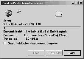
|
Steps 1 to 7 demonstrated how to apply QoS configuration to the access port connected to Host X. You now configure QoS on the trunk port (GigabitEthernet0/4) to the untrusted network. Step 8. | Create an aggregate policer called UNTRUSTED, that defines a traffic rate of 1 Mbps and a burst size of 64000 bytes. Any traffic that does not conform to the rate should be dropped. Example 9-39 shows the configuration required.
Example 9-39. Creating an Aggregate Policer XYZSW1# configure termina1 XYZSW1(config)# mls qos aggregate-police UNTRUSTED 1000000 64000 exceed-action drop
| Step 9. | Create a policy map called UNTRUSTED, and configure a voice traffic class to set the DSCP value of voice traffic to 46. Apply the aggregate policer you created in Step 7 to each class map to rate limit all traffic processed by the entire policy map. Example 9-40 shows the configuration required.
Example 9-40. Creating a Class Map on XYZSW1 XYZSW1# configure terminal XYZSW1(config)# policy-map UNTRUSTED XYZSW1(config-pmap)# class-map VOICE access-group 100 XYZSW1(config-pmap-c)# set ip dscp 46 XYZSW1(config-pmap-c)# police aggregate UNTRUSTED XYZSW1(config-pmap-c)# exit XYZSW1(config-pmap)# end
| Step 10. | Bind the policy you created to the interface attached to the untrusted network (GigabitEthernet0/4) in the ingress direction, as shown in Example 9-41.
Example 9-41. Binding QoS Policy on the Ingress to Interface gig0/3 XYZSW1# configure termina1 XYZSW1(config)# interface GigabitEthernet0/4 XYZSW1(config-if)# service-policy input UNTRUSTED XYZSW1(config-if)# end
| Step 11. | Repeat Step 6 to verify the UNTRUSTED policy map configuration and ensure it is bound to the correct interface.
|
Configuring Access Layer QoS on XYZSW2 XYZSW2 is a combined access/distribution layer Catalyst 6000/6500 switch that provides access layer connectivity for XYZR1. In this section, you configure the QoS for the access layer port connected to XYZR1 to classify traffic based upon access control lists. Step 1. | Enable quality of service features on XYZSW2, as shown in Example 9-42.
Example 9-42. Enabling QoS on XYZSW2 XYZSW2> (enable) set qos enable QoS is enabled.
| Step 2. | Configure the trust state of port 2/3 (connected to XYZR1) as untrusted, as shown in Example 9-43.
Example 9-43. Configuring Port Trust State on XYZSW2 XYZSW2> (enable) set port qos 2/3 trust untrusted Port 2/3 qos set to untrusted
NOTE The default port trust configuration is untrusted, so the configuration shown in Example 9-43 is not necessary but is for demonstration purposes only. | Step 3. | Configure a QoS ACL on XYZSW2 to identify voice traffic between XYZR1 and the rest of the network. Configure the ACL to mark VoIP traffic with a DSCP value of 46, mark VoIP control traffic with a DSCP value of 26, mark business critical traffic with a DSCP value of 28 and to mark all other traffic with a DSCP value of 8, as shown in Example 9-44.
Example 9-44. Configuring a QoS ACL on XYZSW2 XYZSW2> (enable) set qos acl ip XYZR1 dscp 46 udp any range 16384 32767 any range 16384 32767 XYZR1 editbuffer modified. Use 'commit' command to apply changes. XYZSW2> (enable) set qos acl ip XYZR1 dscp 26 tcp any any eq 1720 XYZR1 editbuffer modified. Use 'commit' command to apply changes. XYZSW2> (enable) set qos acl ip XYZR1 dscp 26 tcp any any range 11000 11999 XYZR1 editbuffer modified. Use 'commit' command to apply changes. XYZSW2> (enable) set qos acl ip XYZR1 dscp 26 tcp any any eq 2000 XYZR1 editbuffer modified. Use 'commit' command to apply changes. XYZSW2> (enable) set qos acl ip XYZR1 dscp 28 tcp any any eq 10000 XYZR1 editbuffer modified. Use 'commit' command to apply changes. XYZSW2> (enable) set qos acl ip XYZR1 dscp 8 any XYZR1 editbuffer modified. Use 'commit' command to apply changes.
| Step 4. | Commit the QoS ACL to hardware and attach the ACL to port 2/3, as shown in Example 9-45.
Example 9-45. Committing a QoS ACL and Binding a QoS ACL to an Interface XYZSW2> (enable) commit qos acl XYZR1 Hardware programming in progress... ACL XYZR1 is committed to hardware. XYZSW2> (enable) set qos acl map XYZR1 2/3 Hardware programming in progress... ACL XYZR1 is attached to port 2/3.
| Step 5. | Verify the QoS ACL you just created by using the show qos acl command, as shown in Example 9-46.
Example 9-46. Verifying QoS ACL Configuration on XYZSW2 XYZSW2> (enable) show qos acl info XYZR1 set qos acl ip XYZR1 ---------------------------------------------------- 1. dscp 46 udp any range 16384 32767 any range 16384 32767 2. dscp 26 tcp any any eq 1720 3. dscp 26 tcp any any range 11000 11999 4. dscp 26 tcp any any eq 2000 5. dscp 28 tcp any any 10000 2. dscp 8 any XYZSW2> (enable) show qos acl map XYZR1 ACL name Vlan # Ports -------- ---------------- --------------- XYZR1 1 2/3
|
Step 4Configuring QoS at the Distribution Layer In this step, you configure QoS functions at the distribution layer of the switched network, which includes the switches XYZSW1 and XYZSW2. You now perform the following: - Configure distribution layer QoS on XYZSW1
- Configure distribution layer QoS on XYZSW2
Configuring Distribution Layer QoS on XYZSW1 In this section, you configure distribution layer QoS features on XYZSW1. This includes configuration of each of the inter-switch trunks to XYZSW2 and XYZSW3. The goal of a well-designed end-to-end QoS network is to move as much classification policy to the edge (access layer) of the network, which simplifies the distribution and core layers QoS configuration. In this section, you also configure egress queuing and scheduling. Step 1. | Configure XYZSW1 to trust the DSCP on IP packets received from XYZSW2 (port GigabitEthernet0/1) and then verify your configuration, as shown in Example 9-47.
Example 9-47. Configuring XYZSW1 Port Trust XYZSW1# configure termina1 XYZSW1(config)# interface GigabitEthernet0/1 XYZSW1(config-if)# mls qos trust dscp XYZSW1(config-if)# end XYZSW1#show mls qos interface GigabitEthernet0/1 GigabitEthernet0/2 trust state: trust dscp COS override: dis default COS: 0 DSCP Mutation Map: Default DSCP Mutation Map
| Step 2. | Configure XYZSW1 to trust the CoS on tagged frames received from XYZSW3 (port GigabitEthernet0/2) and then verify your configuration as shown in Example 9-48.
Example 9-48. Configuring XYZSW1 Port Trust XYZSW1# configure termina1 XYZSW1(config)# interface GigabitEthernet0/2 XYZSW1(config-if)# mls qos trust cos XYZSW1(config-if)# end XYZSW1#show mls qos interface GigabitEthernet0/2 GigabitEthernet0/2 trust state: trust cos COS override: dis default COS: 0 DSCP Mutation Map: Default DSCP Mutation Map
|
In Steps 1 and 2, you have configured the ingress on each inter-switch trunk to trust QoS information received in each frame. Because you have performed the required classification and marking at the edge of the network, XYZSW1 can simply trust the QoS marking on each frame, simplifying the QoS processing at the distribution layer. Step 3. | Configure the CoS-to-DSCP map on XYZSW1 to assign a DSCP value of 46 to any frames that possess a CoS of 5 as shown in Example 9-49.
|
NOTE When you modify the CoS-to-DSCP map you must configure all the DSCP values that correspond to each CoS, modifying only the DSCP values you want. Table 9-6 shows the default CoS-to-DSCP map.
Table 9-6. The Default CoS-to-DSCP mapClass of Service | 0 | 1 | 2 | 3 | 4 | 5 | 6 | 7 | DSCP | 0 | 8 | 16 | 24 | 32 | 40 | 48 | 56 |
Example 9-49. Configuring the CoS-to-DSCP Map on XYZSW1 XYZSW1# configure termina1 XYZSW1(config)# mls qos map cos-dscp 0 8 16 24 32 46 48 56 XYZSW1(config-if)# end XYZSW1# show mls qos maps cos-dscp Cos-dscp map: cos: 0 1 2 3 4 5 6 7 -------------------------------- dscp: 0 8 16 24 32 46 48 56
In Example 9-49, you configure the Cos-to-DSCP map so that any frames received with a CoS of 5 are marked with a DSCP value of 46 (instead of the default 40). This is required because XYZSW3 is capable of marking only CoS values. When XYZSW3 sends voice traffic to XYZSW1 for transport, it contains a CoS of 5 in the 802.1p field of the 802.1Q tag. If you use the default CoS-to-DSCP map, XYZSW1 generates a DSCP of 40. By modifying the map, you now effectively classify voice traffic from XYZSW3 with a DSCP of 46, which is consistent with the QoS policy you have configured on XYZSW1 so far. NOTE The CoS-to-DSCP map applies globally to the switch and is used for any ports that are configured to trust CoS.
You have now configured the classification and marking functions on XYZSW1. Next, you configure queuing and scheduling on XYZSW1. Step 4. | Configure the CoS-to-Queue map on the GigabitEthernet0/1, GigabitEthernet0/2, and GigabitEthernet0/4 trunks of XYZSW1 to assign the CoS values of 02 to queue 1, CoS values of 34 to queue 2, CoS values of 67 to queue 3, and the CoS value of 5 to queue 4. Assign a weight of 10 to queue 1, a weight of 40 to queue 2, a weight of 50 to queue 3, and a weight of 0 to queue 4. Configure queue 4 to be a priority queue, ensuring service before any other queue. Example 9-50 shows how to perform this configuration.
Example 9-50. Configuring the CoS-to-Queue Interface gig0/1 Map on XYZSW1 XYZSW1# configure termina1 XYZSW1(config)# interface GigabitEthernet0/1 XYZSW1(config-if)# wrr-queue cos-map 1 0 1 2 XYZSW1(config-if)# wrr-queue cos-map 2 3 4 XYZSW1(config-if)# wrr-queue cos-map 3 6 7 XYZSW1(config-if)# wrr-queue cos-map 4 5 XYZSW1(config-if)# wrr-queue bandwidth 10 40 50 0 XYZSW1(config-if)# priority-queue out XYZSW1(config-if)# exit XYZSW1(config)# interface GigabitEthernet0/2 XYZSW1(config-if)# wrr-queue cos-map 1 0 1 2 XYZSW1(config-if)# wrr-queue cos-map 2 3 4 XYZSW1(config-if)# wrr-queue cos-map 3 6 7 XYZSW1(config-if)# wrr-queue cos-map 4 5 XYZSW1(config-if)# wrr-queue bandwidth 10 40 50 0 XYZSW1(config-if)# priority-queue out XYZSW1(config-if)# exit XYZSW1(config)# interface GigabitEthernet0/4 XYZSW1(config-if)# wrr-queue cos-map 1 0 1 2 XYZSW1(config-if)# wrr-queue cos-map 2 3 4 XYZSW1(config-if)# wrr-queue cos-map 3 6 7 XYZSW1(config-if)# wrr-queue cos-map 4 5 XYZSW1(config-if)# priority-queue out XYZSW1(config-if)# wrr-queue bandwidth 10 40 50 0 XYZSW1(config-if)# end
|
In Example 9-50, the default queuing configuration is modified using the wrr-queue cos-map command so that all voice traffic (CoS of 5) is placed into queue 4. Queue 4 is then enabled as the strict priority queue by the use of the priority-queue out command, meaning all voice traffic (any traffic with a CoS of 5) is given priority service on the interface. The weighting of each of the remaining queues (queue 13) is configured using the wrr-queue bandwidth command such that low-priority traffic (CoS 02) is apportioned 10 percent (10/100), medium-priority traffic (CoS 34) is apportioned 40 percent (40/100), and high-priority traffic (CoS 6-7) is apportioned 50 percent (50/100) of the bandwidth. The bandwidth weighting for queue 4 is ignored because queue 4 has been enabled as the priority queue and is always serviced before any other queues. Step 5. | Configure WRED on egress queue 2 for interfaces GigabitEthernet0/1, GigabitEthernet0/2, and GigabitEthernet0/4 of XYZSW1. Configure the first drop threshold of queue 2 at 60 percent and the second drop threshold of queue 2 at 80 percent. Then configure the DSCP-to-threshold map to apply any traffic with a DSCP of 28 (business critical traffic) to the first drop threshold and any traffic with a DSCP of 26 (VoIP control traffic) to the second drop threshold. Example 9-51 shows the required configuration.
Example 9-51. Configuring WRED on XYZSW1 XYZSW1# configure termina1 XYZSW1(config)# interface GigabitEthernet0/1 XYZSW1(config-if)# wrr-queue random-detect max-threshold 2 60 80 XYZSW1(config-if)# wrr-queue dscp-map 1 28 XYZSW1(config-if)# wrr-queue dscp-map 2 26 XYZSW1(config-if)# exit XYZSW1(config)# interface GigabitEthernet0/2 XYZSW1(config-if)# wrr-queue random-detect max-threshold 2 60 80 XYZSW1(config-if)# wrr-queue dscp-map 1 28 XYZSW1(config-if)# wrr-queue dscp-map 2 26 XYZSW1(config-if)# exit XYZSW1(config)# interface GigabitEthernet0/4 XYZSW1(config-if)# wrr-queue random-detect max-threshold 2 60 80 XYZSW1(config-if)# wrr-queue dscp-map 1 28 XYZSW1(config-if)# wrr-queue dscp-map 2 26 XYZSW1(config-if)# end
|
In Example 9-51, you have set the drop thresholds for queue 2 on each egress interface at 60 percent and 100 percent. This means that when the queue buffer fills to 60 percent capacity, business critical packets will begin to be randomly discarded with heavier flows more likely to experience drops. When the queue buffer fills to 80 percent capacity, VoIP control traffic will also start to be randomly discarded. Having this configuration makes it less likely for voice control traffic to be dropped, and also avoids a tail drop condition for all traffic when the queue reaches 100 percent capacity. NOTE WRED is only supported on weighted round robin queues. If strict priority scheduling is configured for a queue, any WRED configuration for the queue is ignored.
Step 6. | Verify your queuing and scheduling configuration by using the show mls qos interface command, as shown in Example 9-52.
Example 9-52. Verifying Egress Queuing and Scheduling Configuration on XYZSW1 XYZSW1# show mls qos interface GigabitEthernet0/1 queuing GigabitEthernet0/1 Ingress expedite queue: dis Egress expedite queue: ena wrr bandwidth weights: qid-weights 1 - 10 2 - 40 3 - 50 4 - 0 when expedite queue is disabled Dscp-threshold map: d1 : d2 0 1 2 3 4 5 6 7 8 9 --------------------------------------- 0 : 01 01 01 01 01 01 01 01 01 01 1 : 01 01 01 01 01 01 01 01 01 01 2 : 01 01 01 01 01 01 02 01 01 01 3 : 01 01 01 01 01 01 01 01 01 01 4 : 01 01 01 01 01 01 01 01 01 01 5 : 01 01 01 01 01 01 01 01 01 01 6 : 01 01 01 01 Cos-queue map: cos-qid 0 - 1 1 - 1 2 - 1 3 - 2 4 - 2 5 - 4 6 - 3 7 3 XYZSW1# show mls qos interface GigabitEthernet0/1 buffers GigabitEthernet0/1 Notify Q depth: qid-size 1 - 25 2 - 25 3 - 25 4 - 25 qid WRED thresh1 thresh2 1 dis 100 100 2 ena 60 80 3 dis 100 100 4 dis 100 100
|
In Example 9-52, the show mls qos interface GigabitEthernet0/1 queuing command verifies the following information: Priority queuing is enabled, indicated by the Egress expedite queue status. The DSCP-threshold map shows that the DSCP value of 24 is mapped to the second discard threshold. The CoS-queue map shows the CoS values that are mapped to each queue. For example, the CoS value of 5 is mapped to queue 4. The show mls qos interface GigabitEthernet0/1 buffers command shows that WRED is enabled for queue 2 only, with the first threshold (thresh1) set to 60 percent and the second threshold (thresh2) set to 80 percent.
Configuring Distribution Layer QoS on XYZSW2 In this section, you configure distribution layer QoS features on XYZSW2. This includes configuration of classification and queuing/scheduling on each of the inter-switch trunks to XYZSW1 and XYZSW4. Step 1. | Configure XYZSW2 to trust the DSCP on IP packets received from XYZSW1 (port 2/1) and then verify your configuration, as shown in Example 9-53.
Example 9-53. Configuring XYZSW2 Port Trust XYZSW2> (enable) set port qos 2/1 trust trust-dscp Port 1/1 qos set to trust-dscp XYZSW2> (enable) show port qos 2/1 QoS is enabled for the switch. QoS policy source for the switch set to local. Port Interface Type Interface Type Policy Source Policy Source config runtime config runtime ----- -------------- -------------- ------------- ------------- 2/1 - - local local Port TxPort Type RxPort Type Trust Type Trust Type Def CoS Def CoS config runtime config runtime ----- ------------ ------------ ------------ ------------- ------- ------- 2/1 2q2t 1q4t trust-dscp trust-dscp 0 0 ...
| Step 2. | Configure XYZSW2 to trust the CoS on tagged frames received from XYZSW4 (port gig2/2), as shown in Example 9-54.
Example 9-54. Configuring XYZSW2 Port Trust XYZSW2> (enable) set port qos 2/2 trust trust-cos Port 1/1 qos set to trust-cos
|
In Steps 1 and 2, you have configured the ingress on each inter-switch trunk to trust the QoS information received in each frame, because each trunk is connected to a switch that has correctly configured QoS policy. Step 3. | Configure and verify the CoS-to-DSCP map on XYZSW2 to assign a DSCP value of 46 to any frames that possess a CoS of 5, as shown in Example 9-55.
Example 9-55. Configuring the CoS-to-DSCP map on XYZSW1 XYZSW2> (enable) set qos cos-dscp-map 0 8 16 24 32 46 48 56 QoS cos-dscp-map set successfully. XYZSW2> (enable) show qos maps cos-dscp-map CoS - DSCP map: CoS DSCP --- --------------- 0 0 1 8 2 16 3 24 4 32 5 46 6 48 7 56
|
You have now configured the classification and marking functions on XYZSW2. Next, you configure queuing and scheduling on XYZSW2. Step 4. | Verify the port capabilities of the trunk ports on XYZSW2 by using the show port capabilities command, as shown in Example 9-56.
Example 9-56. Verifying Port Capabilities on XYZSW2 XYZSW2> (enable) show port capabilities 2/1 Model WS-X6348 Port 2/1 Type 10/100BaseTX Speed auto,10,100 Duplex half,full Trunk encap type 802.1Q Trunk mode on,off,desirable,auto,nonegotiate Channel 2/1-48 Flow control no Security yes Dot1x yes Membership static,dynamic Fast start yes QOS scheduling rx-(1q4t),tx-(2q2t) ...
|
Example 9-56 shows that a single queue with four drop thresholds (1q4t) exists on the receive (rx) or ingress side, while two queues, each with two drop thresholds (2q2t), exist on the transmit (tx) or egress side. Step 5. | Configure the CoS values that are associated with each queue and drop threshold, as shown in Example 9-57. Table 9-7 shows the required configuration.
|
Table 9-7. CoS to Queue/Threshold Mappings for XYZSW2CoS | Queue Number | Threshold Number |
|---|
0 | 1 | 1 | 1 | 1 | 1 | 2 | 1 | 1 | 3 | 1 | 2 | 4 | 1 | 2 | 5 | 2 | 2 | 6 | 2 | 1 | 7 | 2 | 1 |
Example 9-57. Configuring CoS to Queue/Threshold Mappings on XYZSW2 XYZSW2> (enable) set qos map 2q2t tx 1 1 0,1,2 Qos tx priority queue and threshold mapped to cos successfully. XYZSW2> (enable) set qos map 2q2t tx 1 2 3,4 Qos tx priority queue and threshold mapped to cos successfully. XYZSW2> (enable) set qos map 2q2t tx 2 1 6,7 Qos tx priority queue and threshold mapped to cos successfully. XYZSW2> (enable) set qos map 2q2t tx 2 2 5 Qos tx priority queue and threshold mapped to cos successfully.
As you can see from Example 9-57, the Catalyst 6000/6500 queues traffic based upon CoS and also uses CoS to determine the drop threshold the traffic is subject to within the queue. This differs from the Catalyst 3550 implementation, where traffic is placed into queues based upon CoS, while traffic is assigned to a drop threshold based upon DSCP rather than CoS. Also notice that the queuing configuration on the Catalyst 6000/6500 is applied globally (i.e., to all ports that are 2q2t), whereas the Catalyst 3550 allows you to specify a custom queuing configuration per-interface. Step 6. | Configure the weightings for each queue, so that queue 1 is allocated 20 percent of bandwidth and queue 2 is allocated 80 percent of the bandwidth, as shown in Example 9-58.
Example 9-58. Configuring the Queue Weightings on XYZSW2 XYZSW2> (enable) set qos wrr 2q2t 12 48 QoS wrr ratio is set successfully.
|
In Example 9-58, the weighting ratio is set to 12:48, which works out to 20 percent:80 percent. You could have set the weighting to 2:8 or 1:4; however, this will not achieve the same results. Each unit of weight is equivalent to 256 bytes and is the actual amount of traffic that the scheduler services before moving to the next queue. For example, if you configure a weight of 20, then the scheduler services 5120 bytes before moving to the next queue. If you use a weighting of 2:8, in byte terms, this works out to 512 bytes:2048 bytes. Now, consider if queue 1 contains a frame that is 1500 bytes in size (this is feasible, since the Ethernet MTU is 1500 bytes). The scheduler cannot chop up the frame into 512 byte pieces; it must send the full frame, even though it exceeds the 512 byte queue servicing limit. You should always set a weighting that services at least the MTU of the interface. On Ethernet networks (MTU = 1500 bytes), therefore, the minimum weighting you should use is 6 (6 * 256 bytes = 1536 bytes). TIP As a rule of thumb on Ethernet interfaces, when configuring queue weights on the Catalyst 6000/6500, I recommend working with multiples of six.
Step 7. | Configure the drop thresholds for the second queue (queue 2) on 2q2t ports, configuring 60 percent as the first drop threshold and 80 percent as the second drop threshold. Example 9-59 shows the required configuration.
Example 9-59. Configuring the 2q2t Drop Thresholds on XYZSW2 XYZSW2> (enable) set qos drop-threshold 2q2t tx queue 2 60 80 Transmit drop thresholds for queue 2 set at 60% and 80%
|
The 2q2t ports support only tail drop as the congestion mechanism and do not support WRED. Because you did not configure the first queue (queue 1), the default configuration of 80 percent for the first threshold and 100 percent for the second threshold applies for queue 1. Step 8. | Verify your configuration of steps 5 through 7 by using the show qos info command, as shown in Example 9-60.
Example 9-60. Verifying QoS Configuration on XYZSW2 XYZSW2> (enable) show qos info config 2q2t tx QoS setting in NVRAM for 2q2t transmit: QoS is enabled CoS = 0 Queue and Threshold Mapping: Queue Threshold CoS ----- --------- --------------- 1 1 0 1 2 1 2 3 4 2 1 6 7 2 2 5 Tx drop thresholds: Queue # Thresholds - percentage (abs values ) ------- ------------------------------------- 1 80% 100% 2 60% 80% Queue Sizes: Queue # Sizes - percentage (abs values ) ------- ------------------------------------- 1 80% 2 20% WRR Configuration: Ports have transmit ratios between queue 1 and 2 of 12:48
|
The config keyword used with the show qos info command displays the QoS configuration as configured in NVRAM. Example 9-60 verifies the following: The correct CoS values are mapped to the appropriate queue and drop threshold within the queue as configured in Step 5. This is shown in the Queue and Threshold Mapping section of the output. The drop thresholds for queue 2 are 50 percent and 100 percent as configured in Step 7. This is shown in the Tx drop thresholds section of the output. The transmit ratio between queue 1 and queue 2 is 12:48. This is shown in the WRR Configuration section of the output.
Step 9. | Use the show qos info runtime command to display the actual byte values used on port 2/1 for the weighted round robin servicing of each queue, as shown Example 9-61.
Example 9-61. Verifying QoS Configuration on XYZSW2 XYZSW2> (enable) show qos info runtime 2/1 Run time setting of QoS: QoS is enabled on 2/1 Port 2/1 has 2 transmit queue with 2 drop thresholds (2q2t). Port 2/1 has 1 receive queue with 4 drop thresholds (1q4t). The qos trust type is set to trust-dscp. CoS = 0 Queue and Threshold Mapping: Queue Threshold CoS ----- --------- --------------- 1 1 0 1 2 1 2 3 4 2 1 6 7 2 2 5 Rx drop thresholds: Queue # Thresholds - percentage (abs values ) ------- ------------------------------------- 1 50% (38912 bytes) 60% (46688 bytes) 80% (62240 bytes) 100% (73696 bytes) Tx drop thresholds: Queue # Thresholds - percentage (abs values ) ------- ------------------------------------- 1 80% (288332 bytes) 100% (360416 bytes) 2 60% (38896 bytes) 80% (77792 bytes) Queue Sizes: Queue # Sizes - percentage (abs values) ------- ------------------------------------- 1 80% (360416 bytes) 2 20% (81888 bytes) WRR Configuration: Ports with speed 100Mbps have ratio of 12:48 between transmit queue 1 and 2 (3072:12288 bytes)
|
Example 9-61 shows you all the byte values used for each QoS parameter. This gives you a perspective on how the switch hardware is actually implementing QoS. |