Scenario 7-5: Configuring Cisco Group Management Protocol (CGMP)
| Cisco Group Management Protocol (CGMP), as the name suggests, is a proprietary protocol that is used to constrain multicast traffic on the LAN for networks that use Cisco routers and switches. In the previous scenario, you learned about IGMP snooping, where Cisco Catalyst switches monitor IGMP conversations between multicast routers and receivers, allowing a switch to dynamically determine the ports that frames with a specific multicast group address should be forwarded out. With IGMP snooping, multicast routers and receivers have no idea that a switch is monitoring IGMP traffic, so IGMP snooping is transparent to the multicast routers and receivers. Multicast routers see IGMP Membership Reports from receivers, and receivers see IGMP Queries generated by multicast routersthe fact that a switch might be monitoring the IGMP traffic between multicast routers and receivers is unbeknownst to either. NOTE IGMP snooping is not really transparent when it comes to the IGMP leave process. As indicated in Figure 7-19, if IGMP snooping is enabled on a Cisco Catalyst switch, a multicast router will not see IGMP Leave Group messages until the last receiver for a group leaves the LAN segment. This quality actually enhances the IGMP leave process, because multicast routers do not need to unnecessarily query the LAN for more receivers when a receiver leaves a group and there are still other receivers on the LAN for the group. To implement IGMP snooping properly, switches must possess knowledge of the IGMP protocol and must be able to look at information located much deeper within IGMP frames than normal frames that the switch receives and forwards. Switches need to be able to forward frames at high speeds because the switches attach to high-speed LAN networks. Thus, switches that support IGMP snooping require more expensive hardware-based components such as IGMP-aware ASICs (as opposed to implementing IGMP snooping in software) to ensure that IGMP snooping does not have an effect on frame-forwarding performance. CGMP provides an alternative approach to IGMP snooping and offloads much of the intelligence required to determine group membership at a Layer 2 level to the multicast routers attached to the LAN. For this reason, CGMP is supported on many earlier low-end Cisco switches, with IGMP snooping supported only on high-end or recent Cisco Catalyst switches that possess enhanced hardware that enables the intelligence required for IGMP snooping while maintaining the frame-forwarding performance of the switch. NOTE Although CGMP requires less switch intelligence and, therefore, offers a multicast traffic control solution for low-end switches, today's low-end switches possess enough intelligence to implement IGMP snooping at a low cost. Because IGMP snooping is essentially transparent to the rest of the network and works with any multicast routers that supports IGMP, it is considered superior in benefits over CGMP, and CGMP is considered a legacy protocol that should be implemented only where IGMP snooping is not supported. Proof of this concept is shown on the next-generation Catalyst 2950 and Catalyst 3550 switches, which support only IGMP snooping and do not support CGMP. That said, there are still major deployments of switches that support only CGMP (e.g., the Catalyst 4000 running CatOS), so it is important you understand CGMP. CGMP OperationCGMP takes quite a different approach to multicast traffic control from IGMP snooping. With CGMP, the intelligence required to determine the multicast groups present on a LAN segment and the receivers attached to the LAN is performed by CGMP-enabled multicast routers attached to the LAN (known as CGMP servers). Multicast routers already possess the required intelligence to a certain extent because they must be able to determine whether a Layer 3 subnet has receivers attached so that they can build the outgoing interface list for routes in the multicast route table. With CGMP enabled, multicast routers take this process one step further by transmitting host-specific group membership information to CGMP-enabled LAN switches (known as CGMP clients) using CGMP messages. Using this mechanism creates a communications channel between multicast routers and switches on the LAN, which is separate to normal IGMP communications. It also reduces the computational requirements for switches because they do not need to perform the logic required to determine multicast group membership. Instead this computation is performed by the multicast router and then transmitted to each switch, with switches simply updating bridge table information based upon the information received. For example, when a receiver attaches to the LAN and sends an IGMP Membership Report message to a local multicast router, the multicast router performs normal IGMP operations, but also sends a CGMP message to the switch that indicates a new receiver exists for a group. Because the multicast router receives the IGMP Membership Report message as an IP packet within an Ethernet frame, the multicast router knows the MAC address of the receiver, which is the source MAC address of the Ethernet frame. The multicast router then sends a CGMP Join message to all switches on the LAN, which includes the multicast group address and the MAC address of the new receiver. The CGMP-enabled switches that receive the message then look up the egress port associated with the MAC address of the receiver and add that port to the egress port list for the group address. CGMP communications are one-way in that CGMP servers (multicast routers) communicate information to CGMP clients (switches), but because CGMP operates separately to IGMP and is used purely to provide CGMP clients with receiver membership for each group, CGMP clients are not required to communicate with CGMP servers. CGMP servers communicate with CGMP clients using CGMP messages, which are sent to a special multicast Ethernet address of 01-00-0C-DD-DD-DD. CGMP messages are made up of the following fields:
Each CGMP message contains a pair of GDA and USA entries that define a specific host (USA) joining or leaving a specific multicast group (GDA). Table 7-4 shows the various combinations of GDA, USA, and Join/Leave fields and each combination's respective meaning.
As you can see from Table 7-4, CGMP messages can be used to indicate several different events that are part of normal multicast operation. Important multicast events on the LAN include the following, which normally occur in the order specified:
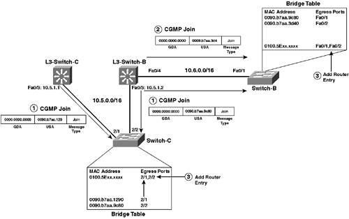
Each of these events and how CGMP communicates these events to CGMP-enabled switches is now examined in detail. Assigning a Router PortWhen a multicast router starts up that has CGMP enabled, the router generates a CGMP Join message with the GDA set to all zeroes and the USA set to the MAC address of the router. This message is multicast out all CGMP-enabled interfaces, ensuring all switches on the LANs the multicast router is attached to receive the message. Referring back to Figure 7-6, assume that L3-Switch-B and L3-Switch-C have just started up, with L3-Switch-B having CGMP configured on interfaces Fa0/3 and Fa0/4, and L3-Switch-C having CGMP configured on interface Fa0/3. This means that on the 10.5.0.0/16 subnet, two CGMP-enabled routers exist (L3-Switch-B and L3-Switch-C). On the 10.6.0.0/16 subnet, even though two multicast routers are attached (L3-Switch-B and L3-Switch-D), only L3-Switch-B is a CGMP-enabled router and, therefore, must communicate information on behalf of L3-Switch-D as well. Also, assume that Switch-B and Switch-C are both CGMP clients. Figure 7-20 demonstrates the process of L3-Switch-B and L3-Switch-C announcing their presence to Switch-C, and L3-Switch-B announcing its presence to Switch-B. Figure 7-20. Assigning a Router Port via CGMP
In Figure 7-20, the following events occur:
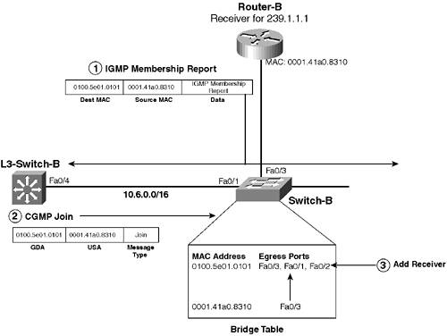
The CGMP Router Join mechanism ensures that any new multicast group entries added to the bridge table (because receivers send Membership Reports to the new group addresses) contain the port or interface that attaches to each CGMP-enabled multicast router on the LAN. This process ensures that multicast routers always receive IGMP Membership Reports from receivers for groups in response to IGMP General Queries that are sent periodically as part of normal IGMP maintenance. Adding Receivers to a GroupWhen receivers attach to the LAN and want to join a multicast group, they issue IGMP Membership Report messages, indicating the multicast group that they want to join. Once the multicast routers attached to the LAN receives these messages, they ensure the router interface that the Membership Report was received on is added to the multicast routing topology. If CGMP is enabled on the interface, the multicast router also sends a CGMP Join message out the interface to communicate the fact that a new receiver has joined a multicast group to all CGMP-enabled switches. Figure 7-21 demonstrates this process on the 10.6.0.0/16 subnet of Figure 7-6, assuming Router-B (a receiver) has just attached to the network. Figure 7-21. Adding Receivers to a Group via CGMP
In Figure 7-21 the following events occur:
If subsequent receivers attach to the LAN for the multicast group, the same events as described in Figure 7-20 occur, except that Switch-B updates an existing bridge table entry for the multicast group, rather than creating a new bridge table entry. NOTE It is important to understand that when multiple CGMP-enabled routers are attached to a LAN segment, only the IGMP Querier (DR) sends CGMP Join messages for receivers that have joined a group. Consequently, on the 10.5.0.0/16 subnet of Figure 7-6, L3-Switch-C sends CGMP Join messages for attached receivers because L3-Switch-C is the IGMP Querier for this subnet (because IGMPv2 is being used and L3-Switch-C has the lowest IP address on this subnet). The same rule applies to CGMP Leave messages (discussed in the next section). Removing Receivers from a GroupWhen receivers want to leave a group, they generate IGMP Leave Group messages. When a CGMP-enabled router receives these messages, it generates a CGMP Leave message and sends this to the LAN to which the receiver is attached to ensure that any CGMP-enabled switches can remove the appropriate port from the egress port list. This process is identical to the events illustrated in Figure 7-21. However, the IGMP Membership Report message is replaced with an IGMP Leave Group message that is addressed to the all multicast routers address (224.0.0.2), and the CGMP Join message is replaced with a CGMP Leave message. If the receiver that is leaving is not the last receiver on the LAN (i.e., other receivers are still attached), the CGMP Leave message specifies the following GDA and USA values:
Each CGMP-enabled switch that receives the CGMP Leave message reads the GDA and USA and removes the interface associated with the USA from the egress port list for the GDA. If the receiver that is leaving is the last receiver on the LAN, the CGMP Leave message includes the multicast group address in the GDA, but includes a USA value of all zeroes (0000.0000.0000), which indicates to all CGMP-enabled switches that there are no more receivers on the LAN and that the bridge table entry for the group address should be deleted from the bridge table. CGMP Local Leave ProcessingLater versions of CGMP on Cisco Catalyst switches include a feature known as local leave processing. This feature is similar to how leave processing is handled with IGMP snooping. When CGMP local leave is enabled, the switch intercepts any IGMP Leave Group messages that are received and then sends an IGMP General Query message out the port that the Leave Group message was received on. If no receivers for the group respond to the General Query, the switch knows that no more receivers for the group are attached to the port, and the port is removed from the egress port list of the bridge table entry for the group address. At this point, if other receivers are still attached to other ports on the switch for the group, the original IGMP Leave Group message is discarded and not forwarded to any multicast routers. However, if there are no more receivers for the group, the switch forwards the IGMP Leave Group message to all multicast routers to ensure that they can prune the LAN interface from the outgoing interface list in the multicast route table entry for the group. NOTE Just as with IGMP snooping, the benefits of local leave processing are realized only for IGMPv2 receivers, because IGMPv2 requires a receiver that wants to leave a group to send a Leave Group message to the 224.0.0.2 (0100.5e00.0002) all multicast routers address, which provides a distinct indication to the switch that a Leave Group message has been generated and the switch CPU should inspect the message. IGMPv1 receivers do not generate a message that indicates they want to leave a group. Rather, they just ignore IGMP General Queries sent by routers to ensure receivers are still active on a segment. In more recent Cisco Catalyst switches, the CGMP local leave feature has been extended to include a fast leave feature, which is identical in function to the IGMP snooping fast leave feature. When fast leave is enabled, Cisco Catalyst switches do not send an IGMP General Query message out the port the Leave Group message was received on, instead assuming that the receiver wanting to leave a group is the only device attached to the switch port. Only enable CGMP fast leave processing if all receivers are directly attached to the switch. Maintaining Group MembershipAs discussed in the IGMP snooping scenario (Scenario 7-4), maintaining group membership is an important consideration for constraining multicast traffic on the LAN. The multicast router that performs the IGMP Querier role for the LAN sends General Query messages periodically to ensure that at least one receiver for every group previously active on the LAN is still active. Receivers use the report suppression mechanism if they hear other IGMP Membership Reports sent by other receivers in response to the General Query messages, which causes an issue for switches that need to know about all receivers attached to the switch. With IGMP snooping, switches ensure that IGMP Membership Reports sent from receivers are not heard by any other receivers on the LAN, which solicits a response from all receivers, ensuring that the switch knows exactly which receivers are still active on the LAN. With CGMP, because this feature lacks a detailed understanding of IGMP, each CGMP-enabled switch simply relies on the multicast routers attached to the LAN to indicate when receivers have left a group. Unfortunately, using this mechanism to maintain group membership on a CGMP-enabled switch is not ideal in the following situations:
NOTE The IGMPv2 specification, unfortunately, does not mandate that receivers must send an IGMP Leave Group message when a receiver wants to leave a group, instead recommending that an IGMP Leave Group should be sent. Consequently, some TCP/IP stacks might implement of IGMPv2 and not generate a Leave Group message when the receiver wants to leave a group. In both of these situations, there is no way for the multicast router attached to a LAN to verify that the receiver has left a group. Hence, no CGMP Leave messages can be generated to indicate to a CGMP-enabled switch that an attached receiver has left a group. The switch continues to forward multicast traffic to receivers who have left the group in the situations just described. These ports cannot be cleared from the egress port list until the group as a whole is removed from the bridge table (i.e., no more receivers are on the LAN for a group). CGMP and IGMP Snooping InteroperabilityIn some networks, due to hardware limitations, you might not be able to run IGMP snooping on all switches, which might create a special scenario where you might need to run CGMP on some switches and also run IGMP snooping in the same LAN. Because CGMP operation relies on multicast routers generating CGMP Joins in response to IGMP Membership Reports sent from receivers, all IGMP Membership Reports must be seen by multicast routers to ensure the appropriate CGMP Joins are generated. IGMP snooping uses a proxy reporting mechanism, which means that not all IGMP Membership Report messages are sent to the multicast router if a group already exists. If CGMP-enabled switches exist in the network, proxy reporting must be disabled on the switches running IGMP snooping, which then ensures all Membership Reports are sent to the multicast router. Cisco Catalyst switches that are running IGMP snooping can detect CGMP messages and can detect that some switches in the network are running CGMP, because they see CGMP multicast messages sent by CGMP-enabled multicast routers. Each switch moves to a special IGMP-CGMP mode that automatically disables the proxy reporting, which ensures CGMP works correctly on the LAN. CGMP Support on Cisco Catalyst SwitchesIt is important to understand that not all Cisco Catalyst switches support CGMP. Table 7-5 lists the various Cisco Catalyst platforms and indicates whether or not CGMP is supported and what minimum software is required. As you can see, CGMP is supported only on the older Cisco Catalyst switches, indicating that CGMP is considered a legacy protocol.
Configuration TasksThe configuration of CGMP consists of the following tasks, which are both required to ensure CGMP operation works correctly:
This scenario uses the topology of Figure 7-6, and referring to Table 7-5, you can see that none of the switches in Figure 7-6 actually support CGMP. For this scenario, assume that Switch-C is a Catalyst 4000 switch running CatOS and that Switch-B is a Catalyst 3500XL switch running Cisco IOS (both of these switches support CGMP). The configuration of CGMP on the 10.5.0.0/16 and 10.6.0.0/16 subnets are demonstrated. Configuring CGMP on a Cisco Multicast RouterCGMP operation on a multicast router (referred to as a CGMP Server) is supported from Cisco IOS version 11.1(2) onwards in all IOS features sets and is supported on all current Cisco router platforms. CGMP Server operation is also supported on Cisco Catalyst Layer 3 Switches, such as the Catalyst 3550, Catalyst 4000/4500 with Supervisor 3/4, and native IOS Catalyst 6000/6500. To enable CGMP on a multicast router, you simply need to enable it on each routed LAN interface that has CGMP-enabled switches attached, which on Cisco Catalyst Layer 3 switches means any physical routed interface or SVI that connects to a VLAN that has CGMP-enabled switches attached. NOTE Each interface that you want to enable CGMP on must have PIM enabled. To enable CGMP on a routed LAN interface that has PIM enabled, use the ip cgmp interface configuration command: Router(config-if)# ip cgmp [proxy | router-only] The optional proxy keyword indicates that the multicast router should generate CGMP Join messages not only for all receivers attached to the LAN and itself, but also for any other non-CGMP multicast routers on the LAN. This feature is known as CGMP proxy and can be configured only on the IGMP Querier (DR) for the LAN. The router-only keyword indicates that the multicast router should generate CGMP Join messages only for itself and other non-CGMP multicast routers on the LAN, without generating CGMP Join messages for receivers on the LAN. This mode of operation is required if you want to use CGMP as the router learning mechanism for IGMP snooping, because the multicast router generates a CGMP Join messages only for itself. Example 7-44 demonstrates configuring CGMP on L3-Switch-C in Figure 7-6 for the interface attached to the 10.5.0.0/16 subnet. Example 7-44. Enabling CGMP on L3-Switch-CL3-Switch-C# configure terminal L3-Switch-C(config)# interface range FastEthernet0/3 L3-Switch-C(config-if-range)# ip cgmp proxy Example 7-45 demonstrates configuring CGMP on L3-Switch-B in Figure 7-6 for the interfaces attached to the 10.5.0.0/16 and 10.6.0.0/16 subnets, assuming that on the 10.6.0.0/16 subnet L3-Switch-D is not configured to support CGMP. Example 7-45. Enabling CGMP on L3-Switch-BL3-Switch-B# configure terminal L3-Switch-B(config)# interface FastEthernet0/3 L3-Switch-B(config-if)# ip cgmp L3-Switch-B(config-if)# exit L3-Switch-B(config)# interface FastEthernet0/4 L3-Switch-B(config-if)# ip cgmp proxy Notice in Example 7-44 that the CGMP proxy feature has been enabled only on interface FastEthernet0/4 and not interface FastEthernet0/3. The CGMP proxy feature is not required on the 10.5.0.0/16 subnet (attached to interface FastEthernet0/3 on L3-Switch-B), because L3-Switch-C is also configured for CGMP on this subnet. On the 10.6.0.0/16 subnet, however, L3-Switch-D is not configured for CGMP; hence, L3-Switch-B must be configured as a CGMP proxy. Because L3-Switch-B has the lowest IP address (10.6.1.1) on the 10.6.0.0/16 subnet, it becomes the IGMP Querier and the CGMP proxy feature works. Configuring CGMP on a Cisco SwitchOnce you have enabled CGMP on all multicast routers on a LAN, or enabled CGMP on at least one multicast router with the CGMP proxy feature configured, you must next enable CGMP on all switches in the LAN. Cisco Catalyst switches operate as CGMP clients, meaning that they are the Layer 2 devices that receive receiver information from multicast routers (CGMP servers). To enable or disable CGMP on a CatOS switch, use the set cgmp command as follows: Console> (enable) set cgmp {enable | disable} By default, CGMP support is disabled. You can also configure CGMP leave and fast leave processing as follows: Console> (enable) set cgmp {leave [enable | disable]} | {fastleave [enable | disable]} The leave keyword enables the CGMP leave processing feature, while the fastleave keyword enables the CGMP fast leave feature. Example 7-46 demonstrates enabling CGMP on Switch-C (a Catalyst 4000 switch for this scenario) in Figure 7-6 and also enabling the CGMP fast leave feature. Example 7-46. Enabling CGMP on a CatOS SwitchSwitch-C > (enable) set cgmp enable CGMP support for IP multicast enabled. Switch-C > (enable) set cgmp fastleave enable CGMP fastleave processing enabled. Once you have enabled CGMP, you should verify that the switch can see the multicast routers attached to the LAN. Example 7-47 demonstrates the show multicast router cgmp command, which is used to display all multicast routers that have been learned via CGMP router joins. Example 7-47. Displaying Multicast Routers Learned via CGMP on CatOSSwitch-C> (enable) show multicast router cgmp Port Vlan ---------- ---------------- 2/1 1 2/2 1 Total Number of Entries = 2 '*' - Configured '+' - RGMP-capable Notice that both L3-Switch-B (connected to port 2/2) and L3-Switch-C (connected to port 2/1) have been learned, because CGMP is configured on both switches. After verifying that the switch can see all multicast routers on the LAN, you should next verify that the correct receiver information is being reported for each group. Example 7-48 demonstrates using the show multicast group command on Switch-C. Example 7-48. Verifying Multicast Group Information Learned via CGMP on CatOSSwitch-C> (enable) show multicast group VLAN Dest MAC/Route Des [CoS] Destination Ports or VCs / [Protocol Type] ---- ------------------ ----- ------------------------------------------- 1 01-00-5e-00-01-28 2/1-2 1 01-00-5e-01-01-01 2/1-2,2/4 Total Number of Entries = 1 In Example 7-48, you can see that the switch has a multicast group entry for 01-00-5e-01-01-01, which is the Ethernet multicast address for the 239.1.1.1 group. Notice that port 2/3 is not included in the destination port list because no receivers are attached to that port. NOTE The 01-00-5e-00-01-28 entry represents the 224.0.1.40 group, which is used for RP discovery and is automatically enabled on Catalyst 3550 Layer 3 switches. On Cisco IOS-based Catalyst switches that support CGMP, such as the Catalyst 2900XL/3500XL, CGMP support is enabled by default, with the CGMP fast leave feature disabled by default. If you want to enable CGMP fast leave, use the cgmp leave-processing global configuration command. Switch(config)# cgmp leave-processing Cisco IOS also allows you to tune a parameter called the CGMP router hold-time, which is the number of seconds the switch waits before removing a router entry after a CGMP Router Leave message has been received. Once a router entry is aged out, all groups associated with that router are also removed. By default this parameter is configured as 400 seconds; however, you can tune this parameter if you want to accelerate the removal of expired group information by using the cgmp holdtime global configuration command: Switch(config)# cgmp holdtime seconds Example 7-49 demonstrates configuring CGMP fast leave and modifying the CGMP router hold-time on Switch-B (a Catalyst 3500XL switch for this scenario). Example 7-49. Enabling CGMP Fast Leave and Modifying CGMP Router Hold-Time on Cisco IOSSwitch-B# configure terminal Switch-B(config)# cgmp leave-processing Switch-B(config)# cgmp holdtime 60 In Example 7-49, remember that CGMP is enabled by default on Cisco IOS switches, so you don't need to explicitly enable CGMP. The CGMP router hold-time has been altered to 60 seconds to allow faster aging out of group information associated with CGMP routers that have send CGMP router leave messages. Once you have configured CGMP on Cisco IOS switches, you should verify that CGMP is working correctly. On Cisco IOS, you can use the show cgmp command to view all CGMP router and group information, as demonstrated on Switch-B in Example 7-50. Example 7-50. Verifying CGMP on Cisco IOSSwitch-B# show cgmp CGMP is running. CGMP Fast Leave is running. CGMP Allow reserved address to join GDA. Default router timeout is 60 sec. vLAN IGMP MAC Address Interfaces ------ ----------------- ----------- 1 0100.5e01.0028 Fa0/1, Fa0/2 1 0100.5e01.0101 Fa0/1, Fa0/2, Fa0/3 vLAN IGMP Router Expire Interface ------ ----------------- -------- ---------- 1 0090.b7aa.9c80 191 sec Fa0/1 1 0009.b7aa.3d40 191 sec Fa0/2 In Example 7-49, you can see that Switch-C knows about both L3-Switch-C and L3-Switch-D, as indicated by the last two shaded lines of the output. The CGMP proxy configuration on L3-Switch-B has ensured that L3-Switch-D is also advertised as a multicast router via CGMP. You can also see that a multicast group entry exists for 0100.5e01.0101, with the appropriate interfaces listed (Fa0/1, Fa0/2, Fa0/3) for multicast forwarding. |
EAN: 2147483647
Pages: 135