Scenario 1-4: Configuring System Time
| In the previous scenarios you have learned how to install Cisco Catalyst switches, configure them for network management, and connect devices. The final base configuration task required is to configure system time, which is very important for ensuring logging information generated by Cisco Catalyst switches includes accurate timestamp information. Often when you are troubleshooting events in the network, you need to correlate external events with specific events that have occurred on your Cisco Catalyst switches. To enable accurate correlation of events, the system date and time must be accurate and ideally synchronized to a central time source used for all devices in the network. This scenario continues on from the previous scenario and shows you how to configure the system clock on Cisco Catalyst switches, as well as configure Network Time Protocol (NTP), which enables Cisco Catalyst switches to obtain time from a trusted time source using IP. Cisco Catalyst switches support NTP client operation, while Cisco routers support both NTP client and NTP server operation. In this scenario, Router-A (see Figure 1-17) is configured as an NTP server, with Switch-A and Switch-B configured as NTP clients that obtains time from Router-A. Scenario PrerequisitesThis scenario requires NTP client support to be configured on Switch-A and Switch-B. Before configuring NTP client support, an appropriate NTP server configuration must be in place on Router-A. Example 1-42 demonstrates the configuration required on Router-A to enable NTP server functionality. Example 1-42. Configuring Router-A as an NTP ServerRouter-A# configure terminal Router-A(config)# clock timezone NZST 12 Router-A(config)# ntp master Router-A(config)# exit Router-A# clock set 17:00:00 7 May 2003 Router-A# show clock 17:00:02.319 NZST Wed May 7 2003 In Example 1-42, the appropriate time zone (New Zealand Standard Time with a +12 UTC offset) is set using the clock timezone command. The ntp master command is then used, which configures Router-A as an NTP server in stratum 7 (default). The clock set command is then used to configure the current date and time. Configuration TasksConfiguring system time on Catalyst switches requires the following configuration tasks:
As you can see from the preceding bullet, configuring network time protocol is optional. However, it is recommended that you use NTP for not just your Cisco Catalyst switches, but all devices in your network, including switches, routers, servers, PCs, and so on. Using the same time source for all your devices ensures that all devices are operating with the same perception of time as all other devices, which enables the job of correlating events collected from different devices much easier when troubleshooting or analyzing trends in the network. Configuring the Correct Date and TimeAll Cisco Catalyst switches possess a clock of some form, whether it is implemented in software, hardware, or both. Some Cisco Catalyst switches operate only a software clock, which is maintained by an operating system process while the switch operating system is loaded. Using just a software clock has the disadvantage that the date and time is reset to some value in the past every time the switch is reset. Some Cisco Catalyst switches operate a software clock and a hardware clock, which allows date and time to be maintained by the hardware clock (typically battery powered) while a switch is reset or if the switch is powered down. Configuring the correct date and time consists of the following tasks:
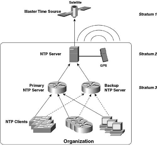
On Cisco IOS, the clock timezone global configuration command is used to configure time zone information, while the clock summer-time global configuration mode is used to configure daylight saving. The clock set privileged mode command is then used to configure the current date and time. Example 1-43 demonstrates configuring date and time on Switch-A. Example 1-43. Configuring the Correct Date and Time on Cisco IOSSwitch-A# configure terminal Switch-A(config)# clock timezone NZST 12 Router-A(config)# clock summer-time NZDT recurring first Sunday October 02:00 3 Sunday March 02:00 60 Switch-A(config)# exit Switch-A# clock set 17:15:00 7 May 2003 Switch-A# show clock .17:15:03.947 NZST Wed May 7 2003 In Example 1-43, a time zone called NZST is created (the name could be anything; however, it might be appended to timestamps in some configurations), which indicates that the local time is 12 hours ahead of UTC time. Daylight saving is then configured, with the daylight saving time zone called NZDT. In Example 1-43, recurring daylight saving is configured that starts on the first Sunday in October at 2:00 a.m. and finishes in the third Sunday in March at 2:00 a.m., with clocks advanced by 60 minutes (1 hour) during the daylight saving period (these settings are the actual correct settings for New Zealand, otherwise known as Middle Earth to fans of "Lord of the Rings"). NOTE If you just configure the recurring keyword for the clock summer-time command without any other parameters (e.g., clock summer-time NZDT recurring), U.S. daylight saving is assumed. The standard U.S. daylight saving configuration is to advance the clock one hour ahead at 2:00 a.m. on the first Sunday in April and then to move the clock back one hour at 2:00 a.m. on the last Sunday in October. Finally, the software clock is set; it is important to set the clock after you configure time zone information, as the Cisco IOS advances or turn back the current system time when time zone information is configured. TIP Notice in the output of the show clock command that the time has a period in front of it (e.g., .17:15:03.947). This means the time is not yet synchronized with its master source. In Example 1-43 the router is synchronizing time using its local clock as the master, and it takes approximately 30 seconds for synchronization. Once the clock is synchronized (either locally as in Example 1-37 or via NTP if an NTP server is configured), the period disappears from the output of the show clock command. On CatOS, the set timezone command is used to configure time zone information, the set summertime command is used to configure daylight saving, and the set time command is used to configure the current date and time. Example 1-44 demonstrates configuring date and time on Switch-B. Example 1-44. Configuring the Correct Date and Time on CatOSSwitch-B> (enable) set timezone NZST 12 Timezone set to 'NZST', offset from UTC is 12 hours Switch-B> (enable) set summertime recurring first Sunday October 02:00 third Sunday March 02:00 60 Summertime is disabled and set to '' Start : Sun Oct 5 2003, 02:00:00 End : Sun Mar 21 2004, 02:00:00 Offset: 60 minutes Recurring: yes, starting at 02:00am of first Sunday of October and ending on 02:00am of third Sunday of March. Switch-B> (enable) set summertime enable NZDT Summertime is enabled and set to 'NZDT' Start : Sun Oct 5 2003, 02:00:00 End : Sun Mar 21 2004, 02:00:00 Offset: 60 minutes Recurring: yes, starting at 02:00am of first Sunday of October and ending on 02:00am of third Sunday of March. Switch-B> (enable) set time 05/07/2003 21:00:00 Wed May 7 2003, 21:00:00 NZST In Example 1-44, notice the same time zone and daylight saving information configured on Switch-A in Example 1-43 is configured on Switch-B. Notice that to enable daylight saving, two commands are required. The first set summertime defines the period over which daylight savings is in effect, while the set summertime enable command is used to enable daylight savings and define a name for the daylight savings time zone. Configuring Network Time ProtocolNetwork Time Protocol (NTP) is a client/server protocol specified for obtaining the correct time from time servers located on IP networks such as the Internet. Any network should have all network device clocks synchronized to aid management. A logging file generated by a network device that does not have the correct time configured is almost useless, because you have no idea as to when events actually occurred. Cisco Catalyst switches can be configured as NTP clients, which obtain time from NTP servers. NTP defines a hierarchy of NTP servers, with the top-level hierarchy or stratum being the most authoritative time source. Lower level NTP servers synchronize time with upper-level NTP servers, which provide a scalable, hierarchical method of distributing accurate time from a root time source. Cisco routers can be configured as NTP servers, and they are commonly configured as the NTP server for other NTP clients, such as servers, other routers, switches, and other devices. The Cisco routers configured as NTP servers typically then obtain time themselves from another NTP server, such as an Internet time server, a server with a GPS device attached that synchronizes time via satellite, or perhaps even a server with an actual timekeeping device attached. Figure 1-20 demonstrates an NTP hierarchy. Figure 1-20. NTP Hierarchy
In Figure 1-20, notice that a pair of routers acting as NTP servers provide time for a large number of NTP clients, such as switches, other routers, servers, and PCs. One router acts as the primary NTP server, and the other router acts as a backup NTP server. Both NTP servers then obtain their time from a higher stratum NTP server, which has a GPS device used to obtain time from a master time source (satellite). The structure of how time is distributed to various devices in Figure 1-20 is very hierarchical. In this scenario, Router-A is an NTP server that provides time for Switch-A and Switch-B. In the configuration prerequisites, the clock on Router-A was configured with the current date and time. Hence, Switch-A and Switch-B can be configured as NTP clients and obtain the correct date and time from Router-A. NOTE Router-A is a Cisco 2610 router that does not have a hardware clock, instead using a software clock that is reset every the switch is reloaded. In real-world scenarios, an accurate time source should be used to provide accurate time. Configuring NTP on Cisco Catalyst switches requires the following configuration tasks:
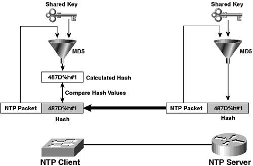
In the previous section you learned how to configure time zone and daylight savings settings; therefore, only the configuration required to define an NTP server and configure NTP authentication is now discussed. Defining an NTP ServerTo configure the NTP client on Cisco IOS, you must define an NTP server using the ntp server global configuration command. Example 1-45 demonstrates configuring an incorrect date and time on Switch-A (assume the current date and time is May 8, 2003, at 2 p.m.), configuring Switch-A to use Router-A as an NTP server and then checking the date and time again after approximately 60 seconds. Example 1-45. Configuring the NTP Client on Cisco IOSSwitch-A# clock set 23:59:59 31 December 1999 Switch-A# show clock .00:00:00.207 NZDT Sat Jan 1 2000 Switch-A# configure terminal Switch-A(config)# ntp server 192.168.1.1 Switch-A(config)# end Switch-A# show clock 14:00:36.865 NZST Thu May 8 2003 Switch-A# show ntp associations address ref clock st when poll reach delay offset disp *~192.168.1.1 127.127.7.1 8 34 64 377 2.1 0.32 0.3 * master (synced), # master (unsynced), + selected, - candidate, ~ configured In Example 1-45, the date and time is first set in the past to 23:59:59 31 December 1999. Router-A is then configured as an NTP server for Switch-B, after which the show clock command is used to check the date and time (you might need to wait up to 60 seconds for the clock to synchronize with the NTP server). Notice that the date, time, and even time zone has been updated to the present. The show ntp associations command is then used to view information about the current status of the NTP server. Notice that *~ precedes the IP address of Router-A, which indicates that the local switch is configured with Router-A as an NTP server and local time is synchronized with Router-A. To define the NTP client on CatOS, the set ntp client command is first used to enable the NTP client, after which an NTP server needs to be defined using the set ntp server command. Example 1-46 demonstrates configuring an incorrect date and time on Switch-B (again, assume the current date and time is approximately May 8, 2003, at 2 p.m.), configuring Switch-B to use Router-A as an NTP server and then checking the date and time again after approximately 60 seconds. Example 1-46. Configuring the NTP Client on CatOSSwitch-B> (enable) set time 12/31/1999 23:59:59 Fri Dec 31 1999, 23:59:59 NZDT Switch-B> (enable) show time Sat Jan 1 2000, 00:00:00 NZDT Switch-B> (enable) set ntp client enable NTP Client mode enabled Switch-B> (enable) set ntp server 192.168.1.1 NTP server 192.168.1.1 added. Switch-B> (enable) show time Thu May 8 2003, 14:04:40 NZST Switch-B> (enable) show ntp Current time: Thu May 8 2003, 14:04:55 NZST Timezone: 'NZST', offset from UTC is 12 hours Summertime: 'NZDT', enabled Start : Sun Oct 5 2003, 02:00:00 End : Sun Mar 21 2004, 02:00:00 Offset: 60 minutes Last NTP update: Thu May 8 2003, 14:34:33 Broadcast client mode: disabled Broadcast delay: 3000 microseconds Client mode: enabled Authentication: disabled NTP-Server Server Key ---------------------------------------- ---------- 192.168.1.1 - Key Number Mode ---------- --------- As you can see in Example 1-46, a similar result occurs on Switch-B after configuring NTP. The show ntp command is then used to verify the NTP configuration. Configuring NTP AuthenticationYou can enhance the security of NTP by using NTP Authentication to enable your NTP client to accept time only from trusted NTP sources. NTP Authentication protects against spoofed NTP packets, where an unauthorized party attempts to change the time on your NTP client by masquerading as the NTP server. This is easily performed by modifying the source IP address of a forged NTP packet to the address of the NTP server. NTP authentication works on the basis of a shared key, which must be configured identically on both the NTP server and client and must be known only to the NTP server and client. Figure 1-21 demonstrates how NTP authentication works. Figure 1-21. NTP Authentication
In Figure 1-21, the contents of each NTP packet sent from the NTP server are hashed together with the shared key using the message digest 5 (MD5) hashing algorithm to produce a hash value (digest) unique to the data input (i.e., it is very unlikely that the same hash value would be derived from different input data). The hash value also cannot be used to derive the original packet contents and key information that was input into the hash algorithm. The hash is then attached to each NTP packet by the NTP server and then sent to the NTP client; the NTP client performs the same hashing algorithm using the NTP packet contents and the locally configured secret key. If the hash value calculated by the client matches the hash value attached to the NTP packet, the client knows that the packet is from the NTP server (because only the NTP server knows the key) and that the integrity of the packet has been maintained in transit (if the packet contents were modified in transit, a different hash value would be calculated). To configure NTP authentication, you must configure it on both the NTP server and NTP client. In this scenario, Router-A is the NTP server; hence, NTP authentication must be configured on Router-A. NTP configuration on Cisco routers and Cisco IOS-based Catalyst switches is the same. To configure NTP authentication on Cisco IOS you must perform the following tasks:
To configure NTP authentication keys, you use the ntp authentication-key global configuration command: Switch(config)# ntp authentication-key key-number md5 key The key-number parameter is a non-zero integer and must match the key number defined on the remote NTP client/server. The md5 keyword specifies MD5 hashing is to be used (at this time, no other hashing algorithms are supported) and the key parameter defines an ASCII secret key value. Once you have defined one or more keys, you then must configure which of those keys are trusted, using the ntp trusted-key global configuration command: Switch(config)# ntp trusted-key key-number The key-number parameter is used to define the authentication key(s) that you want to trust. NOTE It is important that you configure a trusted key using the ntp trusted-key command, because if you do not, Cisco IOS assumes all keys (even those not configured locally) are trusted, which effectively bypasses NTP authentication. Finally, after configuring one or more trusted keys, you must explicitly enable NTP authentication using the ntp authenticate global configuration command. Example 1-47 demonstrates configuring NTP authentication on Switch-A. For NTP authentication to work, an identical configuration is required on Router-A (the NTP server). Example 1-47. Configuring NTP Authentication on Cisco IOSSwitch-A# configure terminal Switch-A(config)# ntp authentication-key 1 md5 cisco123 Switch-A(config)# ntp trusted-key 1 Switch-A(config)# ntp authenticate In Example 1-47, key #1 is configured with a value of cisco123. Assuming the configuration shown in Example 1-47 is configured on Router-A, Switch-A should be able to authenticate Router-A successfully as a trusted time source. This can be tested by changing the current date and time on Switch-A and then waiting for approximately 60 seconds to see if the date and time is re-synchronized with Router-A. Example 1-48 demonstrates testing NTP after authentication has been configured on Switch-A and Router-A. Example 1-48. Testing NTP Operation after NTP Authentication Is ConfiguredSwitch-A# clock set 23:59:59 31 December 1999 Switch-A# show clock .00:00:00.207 NZDT Sat Jan 1 2000 Switch-A# ... (Wait for 60 seconds) ... Switch-A# show clock 14:09:51.123 NZST Thu May 8 2003 In Example 1-48, notice that the clock on Switch-A resynchronizes with Router-A, which indicates NTP authentication is configured appropriately. Now that NTP between Router-A and Switch-A is working with NTP authentication configured, it is now time to move on to Switch-B. To configure NTP authentication on CatOS, you perform the same configuration tasks as for Cisco IOS, configuring a trusted authentication key and enabling NTP authentication. However, you must also associate the appropriate authentication key with the appropriate NTP server. To configure NTP authentication keys, you use the set ntp key configuration command: Console> (enable) set ntp key key-number [trusted | untrusted] md5 key Notice that you can define a key and also configure whether or not the key is trusted in a single command, unlike Cisco IOS which requires two commands. After configuring a trusted key for authentication, you must next associate the key with an NTP server, using the set ntp server command: Console> (enable) set ntp server ntp-server-address key key-number NOTE You can also associate a trusted key with a particular NTP server on Cisco IOS, although this configuration is not required on Cisco IOS. After associating a trusted key with an NTP server, all that remains is to enable NTP authentication, which is achieved using the set ntp authentication {enable | disable} command. Example 1-49 demonstrates configuring NTP authentication on Switch-B, modifying the date and time, and then waiting for approximately 60 seconds to see if NTP is still working. Example 1-49. Configuring and Testing NTP Authentication on CatOSSwitch-B> (enable) set ntp key 1 trusted md5 cisco123 NTP key 1 added. Switch-B> (enable) set ntp server 192.168.1.1 key 1 Key 1 set for NTP server 192.168.1.1 Switch-B> (enable) set ntp authentication enable NTP authentication feature enabled WARNING: NTP client may not communicate with any server if none of the servers has a key configured and set to be trusted Switch-B> (enable) set time 12/31/1999 23:59:59 Fri Dec 31 1999, 23:59:59 NZDT Warning: NTP will override locally set time. Switch-B> (enable) ... (Wait for approximately 60 seconds) ... Switch-B> (enable) show time Thu May 8 2003, 14:15:31 NZST Switch-B> (enable) show ntp Current time: Thu May 8 2003, 14:19:31 NZST Timezone: 'NZST', offset from UTC is 12 hours Summertime: 'NZDT', enabled Start : Sun Oct 5 2003, 02:00:00 End : Sun Mar 21 2004, 02:00:00 Offset: 60 minutes Last NTP update: Thu May 8 2003, 23:18:56 Broadcast client mode: disabled Broadcast delay: 3000 microseconds Client mode: enabled Authentication: enabled NTP-Server Server Key ---------------------------------------- ---------- 192.168.1.1 1 Key Number Mode ---------- --------- 1 trusted In Example 1-49, notice that time is resynchronized successfully via NTP, indicated NTP authentication is working. The output of the show ntp command indicates that that NTP authentication is enabled and also lists the server key associated with the NTP server. |
EAN: 2147483647
Pages: 135