Scenario 1-2: Configuring Network Management Access to the Switch
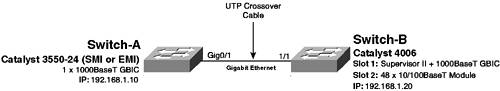
| In the previous scenario, you learned how to install a Cisco Catalyst switch on the network, verify system operation, and also configure switch identity information. The next configuration task is to configure management access so that the switch can be managed via the network. This scenario continues on from the previous scenario and shows you how to configure the various types of network management access available for Cisco Catalyst switches. For this scenario, a new connection is added to the network as shown in Figure 1-13. Figure 1-13. Scenario 1-2 Topology
In Figure 1-13, notice that a gigabit Ethernet connection has been added between Switch-A and Switch-B, which enables IP connectivity and network management access to be tested between Switch-A and Switch-B. To enable gigabit Ethernet connectivity between the two switches, a copper gigabit Ethernet (1000BASE-T) GBIC (Cisco PN# WS-G5483) must be installed into the appropriate GBIC slots on each switch, with a gigabit Ethernet certified unshielded twisted-pair (UTP) crossover cable used to attach each GBIC. NOTE Although gigabit Ethernet is not required between the two switches for the purposes of verifying IP connectivity (you could just use a crossover cable between two Fast Ethernet ports), it is required for Scenario 1-3, where you learn how to configure gigabit Ethernet parameters. By default, Cisco Catalyst switches can be managed only via the console port and require explicit configuration to enable management access using the network. Cisco Catalyst switches can be managed over the network via a variety of mechanisms, which include the following:
Configuration TasksThe following describes the configuration tasks required to enable network management access to Cisco Catalyst switches:
Configuring PasswordsBefore you enable remote EXEC access (via Telnet or SSH) to a Cisco Catalyst switch, you should configure passwords to ensure only authorized administrators can gain EXEC access to the switch over the network. As you have already learned, the default passwords for access to Cisco Catalyst switches via the console are blank (null), and if you configure IP addressing, the same blank passwords are used for controlling Telnet/SSH access. This means your switch is extremely vulnerable if placed on an IP network with IP configured and with no password changes made. Configuring Passwords on Cisco IOSOn Cisco IOS, any password that is used to gain initial user mode access is called a line password, while the password used to gain privileged mode access is called the enable password. On Cisco IOS, remote EXEC access is not granted until at least the line password used for Telnet/SSH access has been explicitly configured. NOTE Cisco IOS uses the concepts of lines to represent the various management interfaces for EXEC access to the switch. Console access is provided by a console line called con 0, while Telnet/SSH access is provided by virtual terminal lines called vty. A number of vty lines exist, which allow for multiple EXEC sessions using Telnet/SSH. Assuming the line password has been configured and administrators can gain user mode access using Telnet/SSH, an enable password must also be explicitly configured if privileged mode access is required via Telnet/SSH. To configure line passwords, you must first access line configuration mode, which is accessed using the line con 0 command to configure the console line or the line vty command to access one or more of the virtual terminal lines. Once line configuration mode is obtained, you can then use the password command to configure a line password. To configure the switch to authenticate users using the line password (known as line authentication), you must also configure the login line configuration command. Example 1-12 demonstrates configuring a line password and enabling line authentication for console access and virtual terminal (telnet/SSH) access on Cisco IOS. Example 1-12. Configuring Line Passwords on Cisco IOSSwitch-A# configure terminal Switch-A(config)# line con 0 Switch-A(config-line)# password cisco Switch-A(config-line)# login Switch-A(config-line)# exit Switch-A(config)# line vty 0 15 Switch-A(config-line)# password cisco Switch-A(config-line)# login Switch-A(config-line)# end Switch-A# In Example 1-12, notice the line con 0 command is configured to gain access to line configuration mode for the console line, as indicated by (config-line) in the prompt. A password of cisco is configured, and line authentication is enabled using the login command. The exit command is then used to return to the parent configuration mode of line configuration mode, which is global configuration mode. Next the line vty 0 15 command is configured to gain access to line configuration mode for all of the virtual terminal lines on the switch (line vty 0 to line vty 15). After the line password is configured and line authentication enabled, notice that the end command is used to return immediately to privileged mode. The end command can be used to immediately exit any configuration mode and return to privileged mode. TIP You can also use the Ctrl--Z key sequence to immediately return from any configuration mode to privileged mode. Now that you understand how to configure line passwords on Cisco IOS, if you want to authenticate privileged mode access after a user gains user mode access via console or virtual terminal access, you must configure an enable password. An enable password is used to prompt for authentication after the enable command is entered from user mode and provides a separate authentication mechanism for providing privileged mode access to the switch. To configure the enable password, you have two options:
You should always use the enable secret command to configure the enable password, because it stores the password in a more secure fashion than the enable password command within the switch configuration file (see Chapter 8, "Traffic Filtering and Security," for more details). Example 1-13 demonstrates configuring an enable password using the enable secret command. Example 1-13. Configuring the Enable Password on Cisco IOSSwitch-A# configure terminal Switch-A(config)# enable secret cisco In Example 1-13, an enable password of cisco is configured. This password is now required when attempting to gain privileged mode access from user mode access. NOTE Always avoid using a simple password like cisco for network devices, especially Cisco devices. This password is most likely the first password an attacker will use to attempt to gain unauthorized access. I only ever use this password in a lab environment, where the device is isolated from any external network. Using this password makes it easy for other co-workers to access the device if they need to perform their own lab testing. Try using passwords that contain a mixture of alphanumeric characters and do not resemble words. If you must use passwords that resemble a word to aid memorizing the password, try to configure the password as an alphanumeric password, replacing characters such as o with 0 and a with 4. It is also important to note that passwords are case sensitive. Configuring Passwords on CatOSOn CatOS, the concept of a line does not exist, with a global user mode password used to authenticate user mode access no matter what management interface is used. Similarly, a global enable password is used to authenticate enable mode access. Unlike Cisco IOS, which does not permit Telnet/SSH access unless a line password has been explicitly configured or privileged mode access via Telnet/SSH unless an enable password has been explicitly configured, CatOS permits Telnet access using blank passwords. This means it is very important that you configure passwords on CatOS before connecting the switch to the network. To configure the password used for user mode access, the set password command is used. To configure the password used for privileged mode access, the set enablepass command is used. Example 1-14 demonstrates configuring passwords for user mode access and enable mode access. Example 1-14. Configuring Passwords on CatOSSwitch-B> (enable) set password Enter old password: In Example 1-14, notice that the set password and set enablepass commands are interactive, in that the switch prompts you for the old password (blank in Example 1-14) and then prompts you to enter and re-enter the new password (cisco in Example 1-14). At this stage, if you logout from the current console EXEC sessions and attempt to access Switch-A or Switch-B via the console port, you should find that you are now prompted for authentication on Switch-A (Cisco IOS) and that blank passwords no longer work on Switch-B. Example 1-15 and Example 1-16 demonstrate logging out of Switch-A and Switch-B respectively and then reconnecting. Example 1-15. Testing Login Authentication on Cisco IOSSwitch-A# logout Switch-A con0 is now available Press RETURN to get started. User Access Verification Password: Example 1-16. Testing Login Authentication on CatOSSwitch-B> (enable) logout Session Disconnected... Cisco Systems, Inc. Console Sun May 4 2003, 20:07:59 Enter password: In Example 1-15 and Example 1-16, the logout keyword is used to disconnect the current console session, after which console access is reattempted. Notice in Example 1-15 that Switch-A now prompts the user for a password, because a line password has been configured for the console. In Example 1-15 and Example 1-16, a blank password is first attempted; however, notice that this fails. A password of "cisco" is then attempted (as indicated by the ***** input), which successfully authenticates providing user mode access. The enable command is then used to attempt access to privileged mode access, and again a password prompt is presented to the user. After an initial unsuccessful authentication attempt using a blank password, the user is successfully authenticating using the cisco enable password, providing privileged mode access to each switch. Configuring IP Addressing and DNSOnce you have configured passwords to secure EXEC access to a Cisco Catalyst switch, you can safely attach the switch to the network and configure an IP address that the switch uses to enable network management. Before configuring IP addressing information, it is important to have a clear understanding of your current network topology and identify exactly where the switch attaches to the network. This enables you to determine the appropriate IP addressing and DNS parameters that are used to configure your switch. The parameters that you need to determine include the following:
Often you might configure only IP addressing and a default gateway, as configuring DNS provides only the ability to resolve host names to IP addresses, which is useful for utilities such as ping and traceroute but not essential to the ongoing management or operation of the switch. Configuring IP Addressing and DNS on Cisco IOSOn Cisco IOS, you configure management interfaces based upon the VLAN that the switch should be managed from. Such an interface is called a switch virtual interface (SVI), which is an internal interface that attaches to the VLAN the SVI belongs to. By default, all Cisco Catalyst switches ship with VLAN 1 as the default VLAN, and by default, the management interface on Cisco IOS is in VLAN 1 as well. To create or configure a management interface on Cisco IOS, you use the interface vlan global configuration command: Switch(config)# interface vlan vlan-id The vlan-id parameter defines the VLAN in which the interface belongs. If the management interface does not already exist (e.g., you are creating a management interface in another VLAN), then a new management interface is automatically created. By default, the VLAN 1 interface exists; however, the interface is placed in a shutdown state. To configure IP addressing on the VLAN 1 interface, you must not only configure an IP address for the interface, but also ensure the interface is enabled using the no shutdown interface configuration command. After enabling the interface, you can configure IP addressing using the ip address interface configuration command as follows: Switch(config-if)# ip address address netmask The address parameter defines the IP address, while the netmask parameter defines the subnet mask in dotted decimal format (e.g., 255.255.255.0). After configuring the IP address of the switch, if the switch is located on a routed network where multiple IP subnets exist, you normally need to configure a default gateway, so that the switch can route packets to destinations not attached to the local subnet. This is achieved using the ip default-gateway global configuration command: Switch(config)# ip default-gateway next-hop-address The next-hop-address defines the IP address of the router through which all non-local IP traffic should be sent. Example 1-17 demonstrates configuring an IP address on Cisco IOS for the VLAN 1 management interface and also configuring a default gateway of 192.168.1.1, assuming a router with this IP address is connected to the network in later scenarios. Example 1-17. Configuring IP Addressing and Configuring a Default GatewaySwitch-A# configure terminal Switch-A(config)# interface vlan 1 Switch-A(config-if)# no shutdown Switch-A(config-if)# ip address 192.168.1.10 255.255.255.0 Switch-A(config-if)# exit Switch-A(config)# ip default-gateway 192.168.1.1 Switch-A(config)# exit Switch-A# show interfaces vlan 1 Vlan1 is up, line protocol is down Hardware is EtherSVI, address is 0009.b7aa.9c80 (bia 0009.b7aa.9c80) Internet address is 192.168.1.10/24 MTU 1500 bytes, BW 1000000 Kbit, DLY 10 usec, reliability 255/255, txload 1/255, rxload 1/255 Encapsulation ARPA, loopback not set ARP type: ARPA, ARP Timeout 04:00:00 Last input never, output never, output hang never Last clearing of "show interface" counters never Input queue: 0/75/0/0 (size/max/drops/flushes); Total output drops: 0 Queueing strategy: fifo Output queue :0/40 (size/max) 5 minute input rate 0 bits/sec, 0 packets/sec 5 minute ouxtput rate 0 bits/sec, 0 packets/sec 0 packets input, 0 bytes, 0 no buffer Received 0 broadcasts, 0 runts, 0 giants, 0 throttles 0 input errors, 0 CRC, 0 frame, 0 overrun, 0 ignored 0 packets output, 0 bytes, 0 underruns 0 output errors, 0 interface resets 0 output buffer failures, 0 output buffers swapped out Switch-A# show ip route Default gateway is 192.168.1.1 Host Gateway Last Use Total Uses Interface ICMP redirect cache is empty In Example 1-17, notice that after the interface vlan 1 command is executed, interface configuration mode is entered, as indicated by the (config-if) prompt. After the no shutdown command is executed, the ip address command is used to configure an IP address of 192.168.1.10/24. NOTE Throughout this book, /nn notation will be commonly used to indicate subnet mask configuration, where nn defines the number of 1s in the subnet mask. For example, a /24 mask represents 11111111 11111111 11111111 00000000, given a subnet mask of 255.255.255.0 in dotted decimal format. After completing the IP addressing configuration, a default gateway of 192.168.1.10 is configured, after which the show interfaces vlan 1 command is used to verify the current status of the VLAN 1 interface. Notice in the first shaded line that the interface is enabled (as indicated by the text "Vlan1 is up"); however, the line protocol (Layer 2 protocol) the interface is down. This is because currently no devices are connected to the switch, meaning there are no active ports in the default VLAN 1; hence, the VLAN 1 SVI stays down. If an active device is connected to the switch, the VLAN 1 SVI comes up, as an active port then exists in VLAN 1. The second shaded line in Example 1-17 indicates the IP address of the interface is now 192.168.1.10 with a subnet mask of 255.255.255.0. Finally, the show ip route command is used to verify the default gateway configuration, as indicated by the last shaded line in Example 1-17. NOTE In Scenario 1-3, where you connect devices to each switch, IP connectivity to Switch-A is verified. To configure DNS on Cisco IOS, you normally configure a domain name to which the switch belongs (used to append domain name information to any name resolution requests for a host name only) and then configure one or more DNS servers that will be used for name resolution. To configure the domain name to which the switch belongs, you use the ip domain-name global configuration command: Switch(config)# ip domain-name domain-name NOTE Configuring a domain name is required for enabling secure shell (SSH) server functionality, which allows for secure network-based EXEC access (instead of using Telnet). Configuring SSH is covered in Chapter 8. To configure DNS servers for name resolution, you must first ensure that DNS lookup is enabled using the ip domain-lookup command (enabled by default) and then configure the ip name-server command: Switch(config)# ip name-server dns-server-1 [dns-server-2] ... [dns-server-6] You can configure up to six name servers, which are tried in the order specified in the ip name-server command. Example 1-18 demonstrates configuring a domain name on Cisco IOS and configuring DNS name resolution. Example 1-18. Configuring DNS on Cisco IOSSwitch-A# configure terminal Switch-A(config)# ip domain-name lanps.com Switch-A(config)# ip domain-lookup Switch-A(config)# ip name-server 192.168.1.100 192.168.1.200 Switch-A(config)# exit Switch-A# ping host-x Translating "host-x"...domain server (192.168.1.100) (192.168.1.200) % Unrecognized host or address, or protocol not running. In Example 1-18, a domain name of lanps.com is configured, which means that the fully qualified domain name (FQDN) of Switch-A is Switch-A.lanps.com. Two DNS servers (192.168.1.100 and 192.168.1.200) are configured, at which time an attempt is made to ping a host by name. Notice the shaded line in Example 1-18, which shows the switch trying to resolve the name "host-x". Because Switch-A is not connected to any devices, the DNS name resolution process fails after waiting 10 seconds for a response from each configured name server respectively. NOTE It is common practice to disable DNS name resolution using the no ip domain-lookup global configuration command on Cisco IOS. If DNS name resolution is enabled, Cisco IOS tries to resolve any mistyped commands that you configure, which takes up to 10 seconds to timeout if no DNS servers are configured (the switch attempts to broadcast DNS queries if no DNS servers are configured). During the name resolution process you cannot type in any other commands, making this occurrence extremely annoying and counter productive. Configuring IP Addressing and DNS on CatOSOn CatOS, several different management interfaces are provided for the purposes of providing management access via an IP network:
By default, the sc0 interface is enabled and is assigned an IP address of 0.0.0.0. All other interfaces are disabled and must be manually enabled. The IP address 0.0.0.0 means that the switch attempts to automatically obtain its IP address via Dynamic Host Configuration Protocol (DHCP) or Reverse Address Resolution Protocol (RARP). If your switch is connected to an existing LAN network and a DHCP or RARP server exists, the switch is automatically assigned an IP address. WARNING Because the sc0 interface attempts to automatically obtain an IP address, you should ensure you have configured a static IP address on the switch before connecting it to the network (unless, of course, you do want to use DHCP or RARP). Connecting the switch to the network before configuring an IP address could allow unauthorized Telnet access if you haven't configured new passwords. To configure the sc0 interface, which allows for in-band management access, you use the set interface sc0 configuration command: Console> (enable) set interface sc0 [vlan-id] ip-address [netmask] [broadcast-address] Console> (enable) set interface sc0 dhcp {renew | release} Console> (enable) set interface sc0 {up | down} Notice that the set interface sc0 command has several different command syntaxes. The first command syntax is the most common syntax used, which defines a static IP address. The optional vlan-id parameter is used to define the VLAN the sc0 interface should attach to (default if omitted is VLAN 1). The required ip-address parameter defines the IP address of the switch, and the optional netmask parameter allows you to define the subnet mask. If the netmask parameter is omitted, a subnet mask based upon the class of the IP address configured (i.e., Class A, B, or C) is assumed. The second command syntax allows you to configure the sc0 for DHCP, while the third command syntax allows you to enable/disable the sc0 interface (default status for the sc0 interface is enabled). After configuring the IP address of the sc0 interface, if the switch is located on a routed network where multiple IP subnets exist, you normally need to configure a default gateway, so that the switch can route packets to destinations not attached to the local subnet. This is achieved using the set ip route default configuration command: Console> (enable) set ip route default gateway-addr [primary] The gateway-addr parameter defines the IP address of the route to which all non-local traffic should be routed, while the optional primary keyword is used to define a primary default gateway if multiple default gateways are configured for redundancy purposes. Example 1-19 demonstrates configuring IP addressing and a default gateway on CatOS. Example 1-19. Configuring IP Addressing on CatOSSwitch-B> (enable) set interface sc0 192.168.1.20 255.255.255.0 Interface sc0 IP address and netmask set. Switch-B> (enable) set ip route default 192.168.1.1 Route added. Switch-B> (enable) show interface sl0: flags=50<DOWN,POINTOPOINT,RUNNING> slip 0.0.0.0 dest 0.0.0.0 sc0: flags=63<UP,BROADCAST,RUNNING> vlan 1 inet 192.168.1.20 netmask 255.255.255.0 broadcast 192.168.1.255 me1: flags=62<DOWN,BROADCAST,RUNNING> inet 0.0.0.0 netmask 0.0.0.0 broadcast 0.0.0.0 Switch-B> (enable) show ip route Fragmentation Redirect Unreachable ------------- -------- ----------- enabled enabled enabled The primary gateway: 192.168.1.1 Destination Gateway RouteMask Flags Use Interface --------------- --------------- ---------- ----- -------- --------- default 192.168.1.1 0x0 UG 0 sc0 192.168.1.0 192.168.1.20 0xffffff00 U 0 sc0 Switch-A(config)# interface vlan 1 In Example 1-19, the set interface sc0 command is first used to configure a static IP address of 192.168.1.20/24, with the sc0 interface placed into VLAN 1 by default as the optional vlan-id parameter is omitted. Next the set ip route default command is used to configure a default gateway of 192.168.1.1. The show interface command indicates that the sc0 interface is up, has an IP address of 192.168.1.20/24, and is in VLAN 1, while the show ip route command verifies that 192.168.1.1 is configured as the default gateway. To configure DNS on CatOS, you must configure a domain name to which the switch belongs using the set ip dns domain command, enable DNS name resolution (disabled by default) using the set ip dns enable command, and then define one or more DNS servers to use for name resolution using the set ip dns server command. Example 1-20 demonstrates configuring DNS on CatOS. Example 1-20. Configuring DNS on CatOSSwitch-B> (enable) set ip dns domain lanps.com Default DNS domain name set to lanps.com Switch-B> (enable) set ip dns enable DNS is enabled Switch-B> (enable) set ip dns server 192.168.1.100 primary 192.168.1.100 added to DNS server table as primary server. Switch-B> (enable) set ip dns server 192.168.1.200 192.168.1.200 added to DNS server table as backup server. Switch-B> (enable) show ip dns DNS is currently enabled. The default DNS domain name is: lanps.com DNS name server status ---------------------------------------- ------- 192.168.1.100 primary 192.168.1.200 backup In Example 1-20, notice that the primary keyword is used with the set ip dns server command to specify the primary DNS server. All other DNS servers configured without the primary keyword are added as backup DNS servers. Finally, the show ip dns command is used to verify DNS is enabled and to also view the name server configuration. Verifying IP ConnectivityAt this stage, both Switch-A and Switch-B have been configured with an IP address and the appropriate passwords have been configured to enable remote EXEC access using Telnet. Because a network connection (gigabit Ethernet connectionsee Figure 1-13) is now in place between Switch-A and Switch-B, you can verify IP connectivity and also test remote EXEC access using Telnet, as both Cisco IOS and CatOS include Telnet client utilities. NOTE The default configuration on the gigabit Ethernet ports on Switch-A and Switch-B means that the connection come up as a trunk (discussed in Chapter 3, "Trunking and Bandwidth Aggregation"), enabling traffic from multiple virtual LANs (VLANs) to be transported across the link. This includes VLAN 1 traffic, which by default both management interfaces on Switch-A and Switch-B belong to, enabling IP communications between the two switches. Both Cisco IOS and CatOS include the ping utility, which can be used to provide a basis test of IP connectivity. Example 1-21 demonstrates the use of the ping utility on Cisco IOS. Example 1-21. Verifying IP Connectivity on Cisco IOSSwitch-A# ping 192.168.1.20 Type escape sequence to abort. Sending 5, 100-byte ICMP Echos to 192.168.1.20, timeout is 2 seconds: !!!!! Success rate is 100 percent (5/5), round-trip min/avg/max = 8/10/20 ms In Example 1-21, connectivity to the IP address of Switch-B (192.168.1.20) is tested. The ping utility generates five ICMP echo request messages, which are sent to the specified IP address. If these messages reach their intended destination, the destination generates an ICMP echo reply message in response to each echo request and then sent the echo reply to the source of the echo request. Notice the shaded output in Example 1-21, which shows five explanation marksthe ! character indicates the switch received an echo reply, indicating a successful response. NOTE Other possible characters that can be displayed include the following:
Example 1-22 demonstrates the use of the ping utility on CatOS. Example 1-22. Verifying IP Connectivity on CatOSSwitch-B> (enable) ping 192.168.1.10 !!!!! ----192.168.1.10 PING Statistics---- 5 packets transmitted, 5 packets received, 0% packet loss round-trip (ms) min/avg/max = 5/7/10 To verify remove EXEC access on each switch, you can use the telnet command on both Cisco IOS and CatOS to establish a Telnet connection to the remote switch. Example 1-23 demonstrates establishing a Telnet connection from Switch-A to Switch-B. Example 1-23. Establishing a Telnet Connection from Cisco IOSSwitch-A# telnet 192.168.1.20 Trying 192.168.1.20 ... Open Cisco Systems, Inc. Console Enter password: ***** Switch-B> enable Enter password: ***** Switch-B> (enable) exit [Connection to 192.168.1.20 closed by foreign host] Switch-A# Example 1-23 verifies that Telnet connectivity to Switch-B is working. Notice that the same interface provided via console access is provided using Telnet (indicated by the shaded output). The password configured for user mode access must be specified to gain initial user mode access, after which the enable password must be specified after the enable command is executed to gain privilege mode access. Example 1-24 demonstrates establishing a Telnet connection from Switch-B to Switch-A. Example 1-24. Establishing a Telnet Connection from CatOSSwitch-B> (enable) telnet 192.168.1.10 Trying 192.168.1.10... Connected to 192.168.1.10. Escape character is '^]'. User Access Verification Password: ***** Switch-A> enable Password: ***** Switch-A# exit Switch-B> (enable) Example 1-24 verifies that Telnet connectivity to Switch-A is working. Notice that the same method of access to gain privileged mode access using a console connection is required when using a Telnet connection. Configuring SNMP SupportNetwork management refers to the processes of configuring, monitoring, and troubleshooting a network device. You've already seen the most direct form of network management for Cisco Catalyst switchesEXEC access through console or Telnet access. When your network starts to grow to hundreds of devices, to provide ongoing management you need to have a central management point that can query and configure each network device from a user-friendly interface. That said, even being able to manage a single switch from a common network management platform is useful as well. The following network management protocols are supported by Cisco Catalyst switches:
Simple Network Management Protocol (SNMP) is the de facto protocol used for monitoring IP-based networks. SNMP provides three key components that make up the management framework:
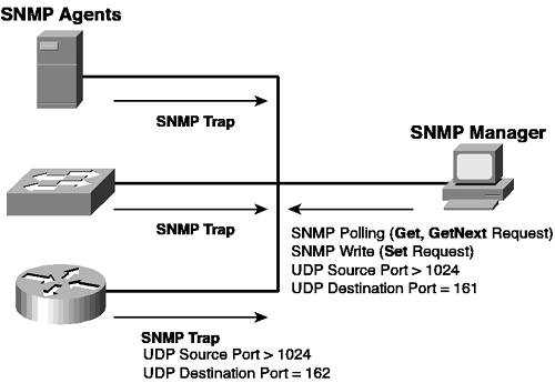
Figure 1-14 shows the components of SNMP. Figure 1-14. SNMP Components
The SNMP manager is a network management station (NMS) that provides centralized management of a number of devices that can be geographically isolated from each other. The SNMP manager is the server portion of the SNMP client/server paradigm, while the SNMP agent is the client port and resides on the managed device. The manager and agent communicate using the SNMP protocol, which is UDP-based using a destination port 161 for messages originated by the SNMP manager and a destination port 162 for SNMP traps originated by SNMP agents (in other words, SNMP agents listen on UDP port 161 for SNMP Get, Set. or GetNext messages, while SNMP managers listen on UDP port 162 for SNMP traps). A manager can poll and configure a device by sending any one of three messages (Get, Set, or GetNext) to an SNMP agent. For example, an NMS might poll a device for its current CPU load by sending a Get request to the agent for the current CPU load. An SNMP agent generates a GetResponse message in response to any of these three messages. An agent can also initiate communications with an NMS by sending a trap or notification to the SNMP manager. This trap is normally sent based upon some event occurring or a specific threshold being exceeded. For example, an SNMP agent might send an SNMP trap to the SNMP manager if the number of errors on a port becomes excessive. Notice in Figure 1-14 that SNMP agents can include servers, routers, switches, and many other devices. In Cisco product terms, Catalyst switches feature SNMP agent support since they are the devices being managed. Cisco has three main network management solutions that provide the SNMP manager component:
The SNMP communications protocol features three access levels that define the type of access the NMS has on the SNMP agent:
NOTE The read-write-all level of access is proprietary to Cisco switches and is not part of the SNMP specification. read-write-all is supported only on CatOS switches (not Cisco IOS-based switches). Each access level is authenticated by using an SNMP community string, which is essentially a password that enables the appropriate access. For the NMS to communicate with an agent at the required access level the NMS and SNMP agent must be configured with the same community string for each access level; otherwise, communications fail. Configuring SNMP Support on Cisco IOSConfiguring SNMP support on Cisco IOS requires the following configuration tasks:
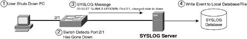
To configure SNMP community strings, you use the snmp-server community global configuration command: Switch(config)# snmp-server community string {ro | rw} [std-access-list] The ro and rw keywords specify the read-only and read-write levels of access, respectively, with the optional std-access-list parameter used to restrict access to only SNMP managers defined in a standard access control list (in Chapter 8 you learn more about restricting SNMP access). Example 1-25 demonstrates enabling SNMP read-only and read-write access on Cisco IOS. Example 1-25. Enabling SNMP Access from SNMP Managers on Cisco IOSSwitch-A# configure terminal Switch-A(config)# snmp-server community readme ro Switch-A(config)# snmp-server community writeme rw Switch-A(config)# snmp-server contact Bob Jones (508)1112222 Switch-A(config)# snmp-server location 999 1st Street, Boston, MA In Example 1-25, a community string of readme is configured for read-only access, and a community string of writeme is configured for read-write access. With this configuration in place, any SNMP manager that attempts to gain access to the switch via SNMP must use a matching community string for the required level of access. Notice the snmp-server contact and snmp-server location commands, which are used to define system information (i.e., contact and location information) about the switch. WARNING Many SNMP manager applications ship with a default read-only community string of public and a default read-write community string of private. Avoid using these community strings in your network, because they are well known and use of these strings can allow unauthorized access to devices on your network. It is also important to note that there are a number of SNMP vulnerabilities detailed on the Cisco Connection Online (CCO) website at www.cisco.com/warp/public/707/cisco-malformed-snmp-msgs-pub.shtml. It is advisable to read this document before configuring SNMP in your network, so that you understand the vulnerabilities that exist and how to mitigate them. To configure SNMP traps, you must first enable traps to be generated using the snmp-server enable global configuration command: Switch(config)# snmp-server enable {traps | informs} [trap-facility1] [trap-facility2...] Notice that you can enable either traps or informs. The only difference between a trap and inform is that a trap is unacknowledged by the receiving SNMP manager, whereas an inform must be acknowledged by the receiving SNMP manager. Therefore, informs are more reliable, because they allow Cisco Catalyst switches to retransmit unacknowledged informs. The optional trap-facility parameters allow you to define the types of events for which traps will be generated. If you do not specify any of these parameters, all events generate traps. After enabling SNMP traps/informs to be generated, you must next configure destination SNMP managers to which traps/informs should be sent using the snmp-server host global configuration command: Switch(config)# snmp-server host manager-ip {traps | informs} [version {1 | 2c | 3}] community-string [trap-facility1] [trap-facility2...] Notice the optional version command, which enables you to configure the version of the SNMP manager as SNMPv1, SNMPv2c, or SNMPv3. SNMPv1 and SNMPv2c rely on community-based authentication, with SNMPv2c supporting additional minor features such as bulk retrieval capabilities and enhanced error reporting. SNMPv3 includes a totally new security model for authenticating and protecting the privacy and integrity of SNMP communications; however, the use of SNMPv3 is not commonplace yet. If you specify a version of 1 or 2c, you must next configure a community string that is used for authenticating with the remote SNMP manager. Example 1-26 demonstrates enabling SNMP traps and configuring a destination to which the traps should be sent. Example 1-26. Configuring SNMP Traps on Cisco IOSSwitch-A# configure terminal Switch-A(config)# snmp-server host 192.168.1.100 readme Switch-A(config)# snmp-server enable traps ? bgp Allow BGP state change traps bridge Allow SNMP STP Bridge MIB traps cluster Allow Cluster Member Status traps config Allow SNMP config traps entity Allow SNMP entity traps envmon Allow environmental monitor traps flash Allow SNMP FLASH traps hsrp Allow SNMP HSRP traps mac-notification Allow SNMP MAC Notification Traps port-security Allow SNMP port-security traps rtr Allow SNMP Response Time Reporter traps snmp Allow SNMP-type notifications syslog Allow SNMP syslog traps tty Allow TCP connection traps udp-port The notification host's UDP port number vlan-membership Allow SNMP VLAN membership traps vlancreate Allow SNMP VLAN created traps vlandelete Allow SNMP VLAN deleted traps vtp Allow SNMP VTP traps Switch-A(config)# snmp-server enable traps Switch-A(config)# exit Switch-A# show snmp Chassis: CAT0620X0HV Contact: Bob Jones (508)1112222 Location: 999 1st Street, Boston, MA 0 SNMP packets input 0 Bad SNMP version errors 0 Unknown community name 0 Illegal operation for community name supplied 0 Encoding errors 0 Number of requested variables 0 Number of altered variables 0 Get-request PDUs 0 Get-next PDUs 0 Set-request PDUs 1 SNMP packets output 0 Too big errors (Maximum packet size 1500) 0 No such name errors 0 Bad values errors 0 General errors 0 Response PDUs 1 Trap PDUs SNMP global trap: enabled SNMP logging: enabled Logging to 192.168.1.100.162, 0/10, 1 sent, 0 dropped. SNMP agent enabled In Example 1-26, an SNMP manager at 192.168.1.100 is configured as a trap destination, with a community string of readme configured for authentication. The snmp-server enable traps ? command is then executed, which provides an indication as to the various types of system events for which you can individually enable/disable SNMP traps for. Notice that the snmp-server enable traps command is then executed, which means all types of system events generate SNMP traps where supported. Finally, the show snmp command is used to verify the SNMP trap configuration. The shaded lines at the bottom of the output indicate that SNMP traps are enabled and are being sent to 192.168.1.100. Configuring SNMP Support on CatOSConfiguring SNMP support on CatOS requires the same configuration tasks as on Cisco IOS, with the configuration of community strings enabling SNMP access to the switch, and the configuration of SNMP traps to allow traps to be forwarded to an external SNMP manager. To configure SNMP community strings, the set snmp community command is used: Console> (enable) set snmp community {read-only | read-write | read-write-all} community-string Notice on CatOS the additional read-write-all access level, which is proprietary and not supported on Cisco IOS. Once the appropriate community strings have been configured, you can configure SNMP traps using the set snmp trap command: Console> (enable) set snmp trap enable [trap-facility1] [trap-facility2...] Example 1-27 demonstrates configuring SNMP management support on CatOS. Example 1-27. Configuring SNMP Community StringsSwitch-B> (enable) set snmp community read-only readme SNMP read-only community string set to 'readme'. Switch-B> (enable) set snmp community read-write writeme SNMP read-write community string set to 'writeme'. Switch-B> (enable) set snmp community read-write-all SNMP read-write-all community string cleared. Switch-B> (enable) set snmp trap 192.168.1.100 readme SNMP trap receiver added. Switch-B> (enable) set snmp trap enable All SNMP traps enabled. Switch-B> (enable) show snmp SNMP: Enabled RMON: Disabled Extended RMON Netflow: Disabled Memory usage limit for new RMON entries: 85 percent EngineId: 00:00:00:09:00:30:24:48:d4:00:00:00 Chassis Alias: Traps Enabled: auth,bridge,chassis,config,entity,entityfru,envfan,envpower, envstate,ippermit,macnotification,module,port,stpx,syslog,system,vlancreate, vlandelete,vmps,vtp Port Traps Enabled: 1/1-2, 2/1-48 Community-Access Community-String ---------------- -------------------- read-only readme read-write writeme read-write-all Additional- Access- Community-String Access-Type Number View -------------------- -------------- ------- ----------------------------------- Trap-Rec-Address Trap-Rec-Community Trap-Rec-Port Trap-Rec-Owner Trap-Rec-Index ---------------- ------------------ ------------- -------------- -------------- 192.168.1.100 readme 162 CLI 1 In Example 1-27, SNMP community strings are configured for read-only and read-write access. Notice that the string for read-write-all access is cleared in Example 1-27 by specifying a null or blank community string, which means no access will be able to gain read-write-all access to the switch via SNMP, because this functionality has been explicitly disabled. WARNING By default on CatOS, all community strings are configured with default values of public, private, and secret for read-only, read-write, and read-write-all access, respectively. This means your switch is vulnerable to unauthorized parties that know the default community strings that are configured on the switch, with the potential for an unauthorized user to configure a switch using read-write access. As a best practice when installing a new CatOS-based switch, you should explicitly clear all SNMP community strings by specifying a null string for each access level and then configure SNMP community stings as required. After SNMP community strings are configured, SNMP traps are then configured to be sent to the host 192.168.1.100, using a community string of readme. The set snmp trap enable command configures all traps to be generated based upon system events. Finally, the show snmp command is used to verify the current SNMP configuration. You can see that SNMP is enabled, and you can see the configured community strings for each level of access (notice the read-write-all string is empty) and information about trap destinations. Configuring SYSLOG SupportSYSLOG is a protocol that is primarily used in UNIX systems and allows for system events to be sent to a central SYSLOG server in a standard message format that indicates the type (or facility) of the message, severity, and details of the message. Figure 1-15 shows how SYSLOG works: Figure 1-15. SYSLOG
In Figure 1-15, the following events take place:
TIP You don't have a SYSLOG server to view SYSLOG messages; you can also configure Cisco Catalyst switches to output SYSLOG messages locally to your console and/or Telnet session, as well as store them in a logging buffer, which is a portion of memory of the switch. In fact by default, Cisco Catalyst switches display SYSLOG messages on the switch console. Obviously, the event depicted in Figure 1-15 is a common occurrence, and as a network administrator, you probably wouldn't want to be flooded with lots of the events at 5 p.m. when users are shutting down to go home. Cisco Catalyst switches enable you to control the type of events and the severity of events for which SYSLOG messages are generated. The facility of a message relates to the category of the event. For example, on Cisco Catalyst switches a facility for system events exists (called sys) and a facility for link events (events related to link states and errors) exists. Within each facility, various messages exist that define events that relate to the facility. NOTE The facilities available vary, depending on the switch model. For an example, see www.cisco.com/univercd/cc/td/doc/product/lan/c3550/12112cea/3550smg/overview.htm#22819 for an example of the complete list of facilities support on a Catalyst 3550 switch. Each message also has a severity that indicates how critical the event is. Table 1-10 shows the severity levels that are used.
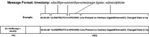
As you can see from Table 1-10, severity level 0 is the highest and severity level 7 is the lowest. Each SYSLOG message has a common format that is displayed in Figure 1-16. Figure 1-16. SYSLOG Message Format
As you can see from Figure 1-16, SYSLOG messages are reasonably simple to read and understand once you know their format. It is important to understand that when SYSLOG messages are sent to a SYSLOG server, a facility tag is attached to each SYSLOG message, which allows the SYSLOG server to identify the application that has generated a SYSLOG message. The facility tag is separate from the actual SYSLOG message that is sent by an application and is always the same value regardless of the SYSLOG message that is attached. Table 1-11 lists the various facility tags that can be configured.
On Cisco Catalyst switches, only a single facility tag can be configured, which is subsequently attached to all messages. Rather than relying on facility tags to identity the application or subsystem internally that generated a message, Cisco uses the facility field in the actual SYSLOG message (see Figure 1-16) to identify the subsystem that generated an event. This means that facility tags are useful only for identifying a particular Cisco device or type of device and are most commonly used to group different types of Cisco devices together. For example, a facility tag of local0 might be configured on all switches in the network, while a facility tag of local1 is configured for all routers in the network. NOTE It is very easy to get confused about the differences between facilities and facility tags. This is because Cisco refers to facility tags using the facility keyword in configuration commands. Configuring SYSLOG Support on Cisco IOSConfiguration of SYSLOG on Cisco IOS is controlled via the logging global configuration command, which has many different parameters that control SYSLOG configuration. To configure support for an external SYSLOG server, you must perform the following configuration tasks:
If you also want to configure other destinations for SYSLOG messages (e.g., console, Telnet sessions), you can use the logging command as follows: Switch(config)# [no] logging {console | monitor | buffered buffer-size} severity-level By default, logging to the console is configured; however, in a production environment it is recommended that you disable console logging to avoid excessive CPU usage (every time an event is logged, an interrupt is sent to the CPU so that the message can be displayed on the console). Notice the buffered keyword, which allows you to allocate a portion of memory (specified in bytes using the buffer-size parameter) that can be used to store SYSLOG events. As indicated in Figure 1-16, every SYSLOG message has a timestamp. On Cisco Catalyst switches, you can configure this timestamp to represent the system uptime or to represent the current date and time. By default on Cisco IOS, no timestamp information is included; however, you can enable timestamps and also modify the format of the timestamp attached to each SYSLOG message by using the service timestamps log global configuration command as follows: Switch(config)# [no] service timestamps log {uptime | datetime [msec | localtime | show-timezone]} The uptime keyword is used to specify that timestamps should be attached that include the system uptime, whereas the datetime keyword is used to specify that timestamps should be attached that include the current date and time. The optional msec keyword specifies the date/time format should include milliseconds, while the localtime specifies the local time should be used in the timestamp (by default UTC time is used) and the show-timezone keyword specifies time zone information should be included in the timestamp. You can use the no service timestamps log command to disable timestamps being used. NOTE The service timestamps debug global configuration command controls the timestamp added to any debugging messages that are displayed as a result of enabling debugging on Cisco IOS. This command has the same options as the service timestamps log command discussed previously. Example 1-28 demonstrates configuring Cisco IOS to perform the following logging-related tasks:
NOTE To view SYSLOG messages from a Telnet session, you must execute the terminal monitor privileged mode command from within the Telnet session. Example 1-28. Configuring SYSLOG Server Support on Cisco IOSSwitch-A# configure terminal Enter configuration commands, one per line. End with CNTL/Z. Switch-A(config)# logging on Switch-A(config)# logging 192.168.1.100 Switch-A(config)# logging trap notifications Switch-A(config)# logging facility local0 Switch-A(config)# no logging console Switch-A(config)# logging monitor critical Switch-A(config)# logging buffered 256000 7 Switch-A(config)# service timestamps log datetime localtime show-timezone Switch-A(config)# exit Switch-A# show logging Syslog logging: enabled (0 messages dropped, 0 messages rate-limited, 0 flushes, 0 overruns) Console logging: disabled Monitor logging: level critical, 0 messages logged Buffer logging: level debugging, 1 messages logged Exception Logging: size (4096 bytes) File logging: disabled Trap logging: level notifications, 1 message lines logged Logging to 192.168.1.100, 1 message lines logged Log Buffer (256000 bytes): *Mar 1 01:07:53 UTC: %SYS-5-CONFIG_I: Configured from console by con0 In Example 1-28, the logging on command ensures that SYSLOG logging is enabled. The logging 192.168.1.100 command defines a SYSLOG server with an IP address of 192.168.1.100 and the logging trap notifications command controls the severity of messages (Level 5 notifications) that are sent to the SYSLOG server. The logging facility local0 command configures the local0 tag to be attached to all SYSLOG messages sent to the server (the default facility tag is local7). Logging to the console is next disabled, with logging to Telnet sessions for critical events enabled and logging to a 256 Kb buffer for all events (level 7 debugging) enabled. All messages are configured to include timestamp information, with the current local date, time, and time zone information included. Finally, the show logging command is used to verify the logging configuration. The output of this command verifies the logging configuration of Example 1-28 and also displays the current log buffer. Notice that a single event exists in the buffer. This event represents exiting from global configuration mode in Example 1-28, which generates a %SYS-5-CONFIG event whenever this happens. You can see that the local date, time and time zone information is included. Because the date and time have not been configured on the switch, an asterisk is present at the beginning of the timestamp. Configuring SYSLOG Support on CatOSTo configure SYSLOG support on CatOS, similar configuration tasks as described for Cisco IOS in the previous section are required, with the set logging command controlling SYSLOG configuration: Console> (enable) set logging {server | console | telnet | session} {enable | disable} Console> (enable) set logging server facility facility-tag Console> (enable) set logging server severity severity-level Console> (enable) set logging buffer message-size Console> (enable) set logging history {message-size | severity severity-level} Console> (enable) set logging level {all | facility} severity [default] Console> (enable) set logging timestamp {enable | disable} As you can see from the first command above, you can selectively enable or disable logging to a SYSLOG server (using the server keyword), to the console (using the console keyword), to all future Telnet sessions (using the telnet keyword), or to the current Telnet session (using the session keyword). The set logging buffer command allows you to define a local buffer in memory for SYSLOG messages, storing up to a maximum configurable number of messages defined by the message-size parameter. The set logging history command allows you to configure SYSLOG messages to be sent in batches to a SYSLOG server, rather than one by one (the default). The message-size parameter for the set logging history command specifies the number of messages that must be generated before sending all of the messages in a single batch to a locally configured SYSLOG server, while the severity severity-level option defines the minimum severity of messages that are stored in the history table. The set logging level command allows you to control the minimum severity of messages to log for each facility on the switch, and the set logging timestamp command allows you to add a timestamp (current system date and time) to each message that is generated (enabled by default). Example 1-29 demonstrates configuring CatOS to perform the following logging-related tasks:
Example 1-29. Configuring SYSLOG Server Support on CatOSSwitch-B> (enable) set logging level all 5 default All system logging facilities set to severity 5(notifications) Switch-B> (enable) set logging server 192.168.1.100 192.168.1.100 added to System logging server table. Switch-B> (enable) set logging server severity 5 System logging server severity set to <5> Switch-B> (enable) set logging server facility local0 System logging server facility set to <local0> Switch-B> (enable) set logging history 10 System logging history table size set to <10> Switch-B> (enable) set logging history severity 7 System logging history set to severity <7> Switch-B> (enable) set logging server enable System logging messages will be sent to the configured syslog servers. Switch-B> (enable) set logging console disable System logging messages will not be sent to the console. Switch-B> (enable) set logging buffer 100 System logging buffer size set to <100> Switch-B> (enable) show logging Logging buffer size: 100 timestamp option: enabled Logging history: size: 10 severity: debugging(7) Logging console: disabled Logging telnet: enabled Logging server: enabled {192.168.1.100} server facility: LOCAL0 server severity: warnings(4) Facility Default Severity Current Session Severity ------------- ----------------------- ------------------------ cdp 5 5 dtp 5 5 dvlan 5 5 earl 5 5 ethc 5 5 filesys 5 5 gvrp 5 5 ip 5 5 kernel 5 5 mcast 5 5 mgmt 5 5 mls 5 5 protfilt 5 5 pruning 5 5 qos 5 5 radius 5 5 security 5 5 snmp 5 5 spantree 5 5 sys 5 5 tac 5 5 tcp 5 5 telnet 5 5 tftp 5 5 udld 5 5 vmps 5 5 vtp 5 5 0(emergencies) 1(alerts) 2(critical) 3(errors) 4(warnings) 5(notifications) 6(information) 7(debugging) Switch-B> (enable) show logging buffer Uptime at Mon May 5 2003, 14:24:33 is 0 day, 3 hours, 11 minutes. 2003 May 05 14:24:25 %SNMP-5-LINKTRAP:Link Down Trap -- ifName=2/1 2003 May 05 14:24:25 %ETHC-5-PORTFROMSTP:Port 2/1 left bridge port 2/1 2003 May 05 14:24:25 %DTP-5-NONTRUNKPORTON:Port 2/1 has become non-trunk 2003 May 05 14:24:31 %SNMP-5-LINKTRAP:Link Up Trap -- ifName=2/1 2003 May 05 14:24:31 %SECURITY-5-DOT1X_PORT_AUTHORIZED:DOT1X: port 2/1 authorized In Example 1-29, the various configuration tasks described preceding the example are implemented. The show logging command is then executed, which displays the current logging configuration allowing you to verify your configuration. Notice the facility table, which lists all of the configurable facilities on the switch and the minimum severity level used to generate events by default and also for the current session. The minimum severity level for all events is 5, due to the set logging level all 5 command executed in Example 1-29. Finally, the show logging buffer command is used to display the logging buffer. In Example 1-29, the events relating to a device being attached to port 2/1 are shown. You can use the clear logging buffer to remove events from the logging buffer. NOTE As a rule of thumb, you should not modify the default severity levels for each facility, because this might result in excessive messages (or a lack of messages) being logged. If you need to modify severity levels to aid in troubleshooting a specific problem, it is best to modify only the security level for the current session by omitting the default keyword in the set logging level command. To restore default security levels for each facility, use the clear logging level command. |
EAN: 2147483647
Pages: 135