Scenario 1-1: Installing a Cisco Catalyst Switch onto the Network
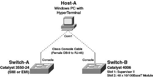
| The first step in successfully integrating Cisco Catalyst switches into the network is to install the switch and configure the switch so that it can operate correctly on the network. In this scenario you learn how to prepare Cisco Catalyst switches for operation on the network. It is important to implement a well-planned switch installation so that you can then attach devices and configure more advanced features with the knowledge that you have a stable platform to build upon. This scenario introduces fundamental configuration tasks of Cisco Catalyst switches that you should know and understand intimately. Figure 1-11 illustrates the topology used for this scenario. Figure 1-11. Scenario 1-1 Topology
In Figure 1-11, Switch-A is a Catalyst 3550 switch, which enables you to learn how to prepare and install Cisco IOS-based switches. Switch-B is a Catalyst 4006 switch, which enables you to how to prepare and install CatOS-based switches. Notice that no devices are actually connected to either switch. In subsequent scenarios, you learn how to configure connectivity for end devices. Configuration TasksIn this scenario, you learn how to perform the following configuration tasks:
Installing the SwitchBefore installing Cisco Catalyst switches onto the network, you must ensure that you have the appropriate hardware required for the switch to operate, as well as other physical requirements such as power, rack space, and the appropriate environmental conditions. On fixed configuration switches, such as the Catalyst 3550, the only hardware you might need to ensure you have are optional gigabit Ethernet GBICs. All other hardware is included with the switch. On chassis-based switches, however, you must ensure you have all the appropriate hardware to run your switch modules correctly. Obviously, at least one Supervisor is required, and you probably need a line card to connect devices to. However, of particular importance on chassis-based switches is power; you must have the appropriate power supplies installed to meet the power requirements of each of the modules installed, and you must understand the requirements for redundant power if this is desired. Table 1-9 lists the AC power requirements for the Catalyst 4000/4500 switches. For the Catalyst 6000/6500 switches, see www.cisco.com/univercd/cc/td/doc/product/lan/cat6000/sw_6_2/confg_gd/admin.htm#46335.
As you can see in Table 1-9, the power requirements for chassis-based switches vary, depending on if you require a redundant power supply and/or if you require inline-powered ports. NOTE For more information on inline power requirements for the Catalyst 4000, see www.cisco.com/warp/public/cc/pd/si/casi/ca4000/prodlit/c4k2_ds.htm. For more information on inline power requirements for the Catalyst 4500, see www.cisco.com/warp/public/cc/pd/si/casi/ps4324/prodlit/inpow_an.htm. Assuming power, rack space, and environmental requirements have been met, in terms of hardware components, if you have a fixed configuration switch (e.g., Switch-A, which is a Catalyst 3550 switch), then the switch will work out of the box without requiring any other components. If you have a chassis-based switch, the following components are required to install the switch and begin configuration:
In this scenario, Switch-B is a chassis-based Catalyst 4006 switch, and it is assumed the following components are used:
Gaining Initial Management AccessAfter ensuring all of the physical components that make up the switch are installed and then physically installing the switch into the rack, the next task is to power on the switch, gain initial management access, and verify that the system has come up correctly and that the system software and hardware configuration is correct. This consists of the following tasks:
Establishing a Console ConnectionOn all Cisco Catalyst switches, a console port is provided, which allows serial access to a command-line interface (CLI) shell that allows you to manage the switch. To gain management access via the console port, the following components are required:
All Cisco Catalyst switches ship with the appropriate cables and adapters that allow you to connect the console port to a male DB-9 serial port on a PC or laptop. Newer Cisco Catalyst switches provide an RJ-45 physical interface for console access. However, older switches might provide a DB-9 or DB-25 interface. In this scenario, both the Catalyst 3550 and Supervisor 2 engine on the Catalyst 4006 provide an RJ-45 console port. After physically connecting your PC or laptop to the console port of the switch, you must next start your terminal emulation application and establish a connection to the console port. All Cisco Catalyst switches provide console port access using the following connection parameters:
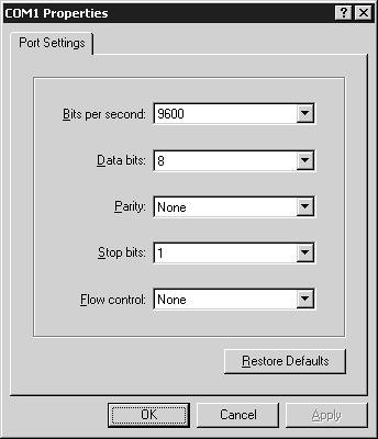
Figure 1-12 demonstrates configuring HyperTerminal with the appropriate serial port settings to gain management access via the console port. Figure 1-12. HyperTerminal Serial Connection Settings
On HyperTerminal, the default speed setting is 2400 bps, with hardware-based flow control enabled, which must be modified to ensure a console connection can be established. Verifying System BootupAfter establishing a console connection, your terminal emulation window just looks blank, because at this stage you have not powered on the switch. After powering on the switch, you should see the switch begin its boot sequence, which is important to monitor to ensure the switch boots correctly. Example 1-1 demonstrates the switch bootup sequence on Switch-A, which is a Cisco IOS-based Catalyst 3550 switch. Example 1-1. System Bootup on the Catalyst 3550 Switch[View full width] Base ethernet MAC Address: 00:09:b7:bb:8d:08 Xmodem file system is available. The password-recovery mechanism is enabled. Initializing Flash... flashfs[0]: 20 files, 3 directories flashfs[0]: 0 orphaned files, 0 orphaned directories flashfs[0]: Total bytes: 15998976 flashfs[0]: Bytes used: 6593024 flashfs[0]: Bytes available: 9405952 flashfs[0]: flashfs fsck took 15 seconds. ...done Initializing Flash. Boot Sector Filesystem (bs:) installed, fsid: 3 Loading "flash:c3550-i5k2l2q3-mz.121-13.EA1a/c3550-i5k2l2q3-mz.121-13.EA1a.bin" ...############################################################################ ############################################################################### ############################################################################### ############################################################################### ############################################################################### ############################################################################### ########################################################### File "flash:c3550-i5k2l2q3-mz.121-13.EA1a/c3550-i5k2l2q3-mz.121-13.EA1a.bin" uncompressed In Example 1-1, the following processes occur during the boot process:
Example 1-2 demonstrates the switch bootup sequence on Switch-B, which is a CatOS-based Catalyst 4006 switch. Example 1-2. System Bootup on the Catalyst 4006 Switch0:00.574327: Please set IPAddr variable 0:00.574909: Please set Netmask variable 0:00.575267: Please set Broadcast variable 0:00.575633: No gateway has been specified 0:00.576177: Network is not configured WS-X4013 bootrom version 6.1(4), built on 2001.07.30 14:43:26 H/W Revisions: Meteor: 4 Comet: 8 Board: 2 Supervisor MAC addresses: 00:10:7b:f7:2f:00 through 00:10:7b:f7:32:ff (1024 addresses) Installed memory: 64 MB Testing LEDs.... done! The system will autoboot in 5 seconds. Type control-C to prevent autobooting. rommon 1 > The system will now begin autobooting. Autobooting image: "bootflash:cat4000-k8.7-6-1.bin" ................................................................................ ................................................................. ################################ Starting Off-line Diagnostics Mapping in TempFs Board type is WS-X4013 DiagBootMode value is "post" Loading diagnostics... Power-on-self-test for Module 1: WS-X4013 Status: (. = Pass, F = Fail) processor: . cpu sdram: . temperature sensor: . enet console port: . nvram: . switch sram: . switch registers: . switch port 0: . switch port 1: . switch port 2: . switch port 3: . switch port 4: . switch port 5: . switch port 6: . switch port 7: . switch port 8: . switch port 9: . switch port 10: . switch port 11: . switch bandwidth: . Module 1 Passed Power-on-self-test for Module 2: WS-X4148 Port status: (. = Pass, F = Fail) 1: . 2: . 3: . 4: . 5: . 6: . 7: . 8: . 9: . 10: . 11: . 12: . 13: . 14: . 15: . 16: . 17: . 18: . 19: . 20: . 21: . 22: . 23: . 24: . 25: . 26: . 27: . 28: . 29: . 30: . 31: . 32: . 33: . 34: . 35: . 36: . 37: . 38: . 39: . 40: . 41: . 42: . 43: . 44: . 45: . 46: . 47: . 48: . Module 2 Passed Exiting Off-line Diagnostics IP address for Catalyst not configured BOOTP/DHCP will commence after the ports are online Ports are coming online ... Cisco Systems, Inc. Console Enter password: In Example 1-2, a similar sequence of events as Example 1-1 occurs, with the switch first loading and operating system from Flash, performing a series of successful POST tests on each module in the switch, and then providing an Enter password: prompt, which indicates the switch has successfully booted and initial management access is available. Gaining Privileged Mode AccessAfter system bootup is complete, you should gain initial management access, which allows you to configure, manage, and monitor the switch. NOTE Cisco refers to the management access provided via CLI as EXEC access. On Cisco IOS and CatOS, management access (EXEC access) is provided at two levels by default:
The default levels of EXEC access provided vary, depending on whether or not you are configuring a Cisco IOS-based switch or a CatOS-based switch. On Cisco IOS, any access via the console is granted user mode access by default, which is indicated by the Switch> prompt (see Example 1-1). On CatOS, you must provide a password to gain user mode access via the console, which is indicated by the Enter password: prompt (see Example 1-2). After gaining user mode access, you can then gain privileged mode access by executing the enable command. Each level of EXEC access requires a separate password to gain access; however, by default blank passwords are used to gain access. Example 1-3 demonstrates gaining privileged level access to Switch-A. Example 1-3. Gaining Privileged Level Access on Cisco IOSSwitch> enable Switch# In Example 1-3, user mode access is already granted by default via the console; hence, the enable command needs to be executed only to gain privilege mode access. Notice that privileged mode access is granted immediately, without any prompt for password, as by default no password is required for privileged mode access. The # portion of the Switch# prompt indicates that the current EXEC session has privileged mode access, whereas the > portion of the Switch> prompt indicates the current EXEC session has user mode access. Example 1-4 demonstrates gaining privileged EXEC access to Switch-B. Example 1-4. Gaining Privileged Level Access on CatOSCisco Systems, Inc. Console Enter password: In Example 1-4, a blank password is required to gain user mode access, after which the enable command is executed to gain privileged mode access. Notice that unlike Cisco IOS, CatOS prompts you for a password to gain privileged mode access, even though the default password is blank. The (enable) portion of the Console> (enable) prompt indicates that the current EXEC session has privileged mode accessif only the Console> prompt is displayed, the current EXEC session only has user mode access. Verifying System ConfigurationAfter gaining privileged mode access, you should next verify the system hardware and software configuration is correct. Although system hardware is tested during system bootup, you should also verify the operating system can see all switch hardware after system bootup. As with any operating system, various versions of operating systems exist on Cisco Catalyst switches, which contain various levels of features depending on the version of operating system software installed. Ensuring the appropriate version of operating system software is installed is important, so that you can maintain the same versions of operating system software throughout the network, as well as configure the features required for your network. To verify system hardware and software on Cisco IOS, you can use the show version command, which displays hardware and software versions and other information, as demonstrated in Example 1-5. Example 1-5. Using the show version Command on Cisco IOSSwitch# show version Cisco Internetwork Operating System Software IOS (tm) C3550 Software (C3550-I5K2L2Q3-M), Version 12.1(13)EA1a, RELEASE SOFTWARE (fc1) Copyright 1986-2003 by cisco Systems, Inc. Compiled Tue 25-Mar-03 23:56 by yenanh Image text-base: 0x00003000, data-base: 0x008BA914 ROM: Bootstrap program is C3550 boot loader Switch uptime is 51 minutes System returned to ROM by power-on System image file is "flash:c3550-i5k2l2q3-mz.121-13.EA1a/c3550-i5k2l2q3-mz.121-13.EA1a.bin" This product contains cryptographic features and is subject to United States and local country laws governing import, export, transfer and use. Delivery of Cisco cryptographic products does not imply third-party authority to import, export, distribute or use encryption. Importers, exporters, distributors and users are responsible for compliance with U.S. and local country laws. By using this product you agree to comply with applicable laws and regulations. If you are unable to comply with U.S. and local laws, return this product immediately. A summary of U.S. laws governing Cisco cryptographic products may be found at: http://www.cisco.com/wwl/export/crypto/tool/stqrg.html If you require further assistance please contact us by sending email to export@cisco.com. cisco WS-C3550-24 (PowerPC) processor (revision C0) with 65526K/8192K bytes of memory. Processor board ID CAT0620X0HV Last reset from warm-reset Bridging software. Running Layer2/3 Switching Image Ethernet-controller 1 has 12 Fast Ethernet/IEEE 802.3 interfaces Ethernet-controller 2 has 12 Fast Ethernet/IEEE 802.3 interfaces Ethernet-controller 3 has 1 Gigabit Ethernet/IEEE 802.3 interface Ethernet-controller 4 has 1 Gigabit Ethernet/IEEE 802.3 interface 24 FastEthernet/IEEE 802.3 interface(s) 2 Gigabit Ethernet/IEEE 802.3 interface(s) The password-recovery mechanism is enabled. 384K bytes of flash-simulated non-volatile configuration memory. Base ethernet MAC Address: 00:09:B7:BB:8D:08 Motherboard assembly number: 73-5700-99 Power supply part number: 34-0966-02 Motherboard serial number: CAT062843JA Power supply serial number: LIT0636005A Model revision number: C0 Motherboard revision number: B0 Model number: WS-C3550-24-EMI System serial number: CAT0620Y1JJ In Example 1-5, the shaded lines indicate operating system software version, hardware interfaces recognized by the system, serial number information, and a lot of other information about the system. To verify system hardware on CatOS, you can use the show module command, which lists the various hardware modules installed in chassis-based CatOS switches. You can also use show version command to display hardware and software versions and other information, as demonstrated in Example 1-6. Example 1-6. Verifying Hardware and Software on CatOSConsole> (enable) show module Mod Slot Ports Module-Type Model Sub Status --- ---- ----- ------------------------- ------------------- --- -------- 1 1 2 Supervisor 2 WS-X4013 no ok 2 1 48 10/100 Ethernet WS-X4148 no ok Mod Module-Name Serial-Num --- -------------------- -------------------- 1 JAB05310GME 2 JAB030200QX Mod MAC-Address(es) Hw Fw Sw --- -------------------------------------- ------ ---------- ----------------- 1 00-30-24-48-d4-00 to 00-30-24-48-d7-ff 2.0 6.1(4) 7.6(1) 2 00-30-24-48-d7-9e to 00-30-24-48-d7-fd 2.0 Console> (enable) show version WS-C4006 Software, Version NmpSW: 7.6(1) Copyright 1995-2003 by Cisco Systems, Inc. NMP S/W compiled on Apr 16 2003, 18:56:05 GSP S/W compiled on Apr 16 2003, 16:56:33 System Bootstrap Version: 6.1(4) Hardware Version: 3.2 Model: WS-C4006 Serial #: FOX052202RB Mod Port Model Serial # Versions --- ---- ------------------ -------------------- ------------------------------- 1 2 WS-X4013 JAB05310GME Hw : 3.2 Gsp: 7.6(1.0) Nmp: 7.6(1) 2 48 WS-X4148 JAB030200QX Hw : 1.0 DRAM FLASH NVRAM Module Total Used Free Total Used Free Total Used Free ------ ------- ------- ------- ------- ------- ------- ----- ----- ----- 1 65536K 36714K 28822K 16384K 4458K 11926K 480K 245K 235K Uptime is 0 day, 3 hours, 0 minute In Example 1-6, the show module command provides information specific to each module installed in the switch. You can see that the switch currently recognizes a Supervisor 2 module installed in module 1, and a 48-port module installed in module 2. The Status column indicates that each module is currently operational, as indicated by the value ok. The show version command also provides hardware and software information. The first line of the shaded output indicates the operating system version, while the second line indicates the read-only memory (ROM) software version used to boot the switch. The last shaded line indicates total system memory (64 MB) and Flash (16 MB) and also indicates current memory/Flash usage. Configuring System IdentityAfter installing a Cisco Catalyst switch, gaining initial management access, and verifying the system configuration, you are ready to begin configuring the switch. Configuring a switch for operation on the network might comprise many different configuration tasks specific to your environment; however, several base configuration tasks most administrators will perform, which include the following:
Configuring a Host NameConfiguring a host name for a switch is perhaps the most fundamental configuration task, because it enables you to uniquely identify a switch in the network. Before configuring host name information, it is important to understand how you actually perform configuration on Cisco Catalyst switches. On Cisco IOS, configuration is provided via configuration modes, which are modes that are accessible via privileged mode access. A base configuration mode called global configuration mode provides the ability to configure settings that are applied globally to the switch. Other configuration modes exist for configuring specific components and features of the switch. To access any configuration mode on Cisco IOS, you must first access global configuration mode, which is performed using the configure terminal command via privileged mode access. Example 1-7 demonstrates accessing global configuration mode on a Cisco IOS switch. Example 1-7. Accessing Global Configuration ModeSwitch# configure ? memory Configure from NV memory network Configure from a TFTP network host overwrite-network Overwrite NV memory from TFTP network host terminal Configure from the terminal Switch# configure terminal Enter configuration commands, one per line. End with CNTL/Z. Switch(config)# In Example 1-7, the configure ? command is first executed, which provides online help for the various parameters that you can configure with the configure command. Cisco IOS includes online help as indicated in Example 1-7 for all commands, which can simply be accessed by using the ? character. Notice that you can configure the switch using four different commands:
In Example 1-7, the configure terminal command is executed to allow configuration via the console port. Notice that the switch prompt changes to Switch(config)#, which indicates the switch is currently operating in global configuration mode and accepts global configuration commands. Once in global configuration mode, you can begin configuring the switch. To configure a host name on a Cisco IOS switch, you use the hostname global configuration command, as demonstrated in Example 1-8. Example 1-8. Configuring a Host Name on Cisco IOSSwitch(config)# hostname ? WORD This system's network name Switch(config)# hostname Switch-A ? <cr> Switch(config)# hostname Switch-A In Example 1-8, the hostname ? command is executed to determine the parameters that the command requires. Notice that Cisco IOS indicates a WORD is required that defines the host name. A WORD is essentially a free-text string that is used to describe some parameter on the switch, such as the switch host name. Next, the host name is configured as Switch-A, with another ? character being used to see if any other parameters must be configured. Cisco IOS indicates that a carriage return is required (<cr>), which means the configuration of the command is complete. This means the full command to configure the host name is hostname Switch-A. After this command is executed, notice that the switch name in the command prompt is modified appropriately. Finally, notice that the exit command is used to exit global configuration mode and return to privileged mode access. The exit command can be used within any configuration mode on Cisco IOS to return to the previous mode. On CatOS, all configuration is performed from privileged mode access, with no concept of configuration modes. All configuration commands begin predominantly with the set keyword, and the clear keyword is also used to reset some configuration parameters. To configure the host name of a CatOS-based switch, the set system name command is used, as demonstrated in Example 1-9. Example 1-9. Configuring the Host Name on CatOSConsole> (enable) set system ? Set system commands: ---------------------------------------------------------------------------- set system baud Set system console port baud rate set system contact Set system contact set system help Show this message set system location Set system location set system modem Set system modem control (enable/disable) set system name Set system name Console> (enable) set system name ? <name_string> Name for the system <cr> Console> (enable) set system name Switch-B System name set. Switch-B> (enable) In Example 1-9, notice that you can use the ? character to provide a similar online help mechanism as provided on Cisco IOS. After executing the set system name Switch-B command, notice that the prompt is changed to include the system name. Saving and Verifying Your ConfigurationOn Cisco IOS, any configuration changes made are made to a running configuration file, which is stored in memory and erased if the switch is rebooted or shut down. To ensure any configuration changes you have made are saved permanently, you must explicitly save the running configuration file to the startup configuration file, which is a file stored in nonvolatile RAM (NVRAM) that is read by the switch upon switch bootup. To save the current running configuration to the startup configuration file, you use the copy running-config startup-config command, as demonstrated in Example 1-10. Example 1-10. Configuring a Host Name on Cisco IOSSwitch-A# copy running-config starup-config Destination filename [startup-config]? In Example 1-10, after the running configuration file is saved to the startup configuration file, the show running-config command is executed, which displays the current configuration stored in memory. Notice the highlighted command hostname Switch-A, which you configured in Example 1-8. All other commands are default settings. You can also use the show startup-config command to view the startup configuration file. NOTE You can use the copy startup-config running-config command to copy the startup configuration to the current running configuration; however, be aware that this command is additive, in that any settings currently present in the running configuration file that are not present in the startup configuration file are still maintained. This is unlike the copy running-config startup-config command, where the existing startup configuration file is first erased and then replaced with the running configuration file. On CatOS, all configuration changes are automatically saved, meaning you don't have to explicitly save your configurations. To verify your configuration, you can use the show config command, as demonstrated in Example 1-11. Example 1-11. Verifying Configuration on CatOSSwitch-B> (enable) show config This command shows non-default configurations only. Use 'show config all' to show both default and non-default configurations. ............... .. begin ! # ***** NON-DEFAULT CONFIGURATION ***** ! #time: Wed Mar 3 1993, 02:34:54 ! #version 7.6(1) ! #system web interface version(s) ! #system set system name Switch-B ! #frame distribution method set port channel all distribution mac both ! #ip set interface sl0 down set interface me1 down set ip alias default 0.0.0.0 ! #set boot command set boot config-register 0x10f set boot system flash bootflash:cat4000-k8.7-6-1.bin ! #multicast filter set igmp filter disable ! #module 1 : 2-port Switching Supervisor ! #module 2 : 48-port 10/100 Ethernet end In Example 1-11, the show config command is used to display all non-default configuration settings. You can use the show config all command to view all configuration settings; however, the output of this command is very long, limiting the usefulness of this command if you are trying to extract specific configuration information. You can see highlighted command set system name Switch-B, which you configured in Example 1-9. All other commands are default settings. | ||||||||||||||||||||||||||||||||||||||||
EAN: 2147483647
Pages: 135
- Structures, Processes and Relational Mechanisms for IT Governance
- An Emerging Strategy for E-Business IT Governance
- A View on Knowledge Management: Utilizing a Balanced Scorecard Methodology for Analyzing Knowledge Metrics
- Measuring ROI in E-Commerce Applications: Analysis to Action
- The Evolution of IT Governance at NB Power