Overview of the IMS System Definition Process
| The IMS system definition process comprises many steps. Some steps occur only for certain types of IMS definitions (see "Types of IMS System Definitions" on page 332). The basic steps involved in IMS system definition are:
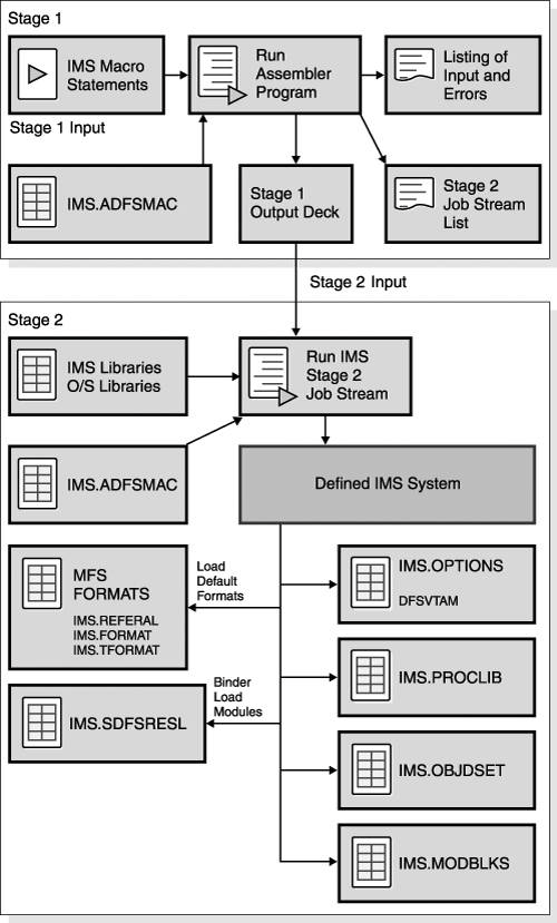
Figure 19-2 on page 331 shows an overview of the stage 1 and stage 2 components of the system definition process. Figure 19-2. Overview of Stage 1 and Stage 2 of the System Definition Process Types of IMS System DefinitionsThere are seven different types of IMS system definitions. You use the IMSCTRL macro statement to describe the type of IMS system definition to be performed, the basic IMS control program options, and the z/OS system configuration under which IMS is to execute. The IMSCTRL options that specify the different types of system definitions are described in Table 19-1.
After your initial system definition, the ON-LINE, CTLBLKS, and NUCLEUS types of system definition can be used to implement changes. The ON-LINE, CTLBLKS, and NUCLEUS types of system definitions require a cold start of the IMS online system to take effect. For certain changes to your IMS system, however, you can take advantage of the online change method using the MODBLKS type of system definition. With the MODBLKS type of system definition, the changes are made active during the execution of the online system and do not require a restart operation. Related Reading: For the details about the different types of system definition, see "Using the Macro Table" in IMS Version 9: Installation Volume 2: System Definition and Tailoring. Stage 1 of the IMS System Definition ProcessStage 1 of the system definition process uses the z/OS High Level Assembler program and uses the IMS macros as input, as described in "IMS System Definition Macros" on page 335. Other references are to the IMS distribution macro libraries (IMS.ADFSMAC). The output from stage 1 of the IMS system definition process includes:
Depending on what is specified in the IMSGEN macro[1] for stage 1, stage 2 of the system definition process can be divided up into a single job with multiple steps, or into many jobs with fewer steps.
Stage 2 of the IMS System Definition ProcessStage 2 of the system definition process assembles and binds all the modules that are required to build the necessary load modules, depending on what type of system definition is being run. The steps involved in stage 2 refer to the IMS distribution macro library (IMS.ADFSMAC) at assembly time, and the distribution load library (IMS.ADFSLOAD) at bind time. The output of stage 2 of the system definition process includes:
JCLIN ProcessingBecause the stage 2 system definition process actually assembles and binds the IMS modules based on the definitions for that particular system and is run outside of SMP/E control, the input JCL for system definition stage 2 must be used as input to the JCLIN process. This input JCL ensures that SMP/E knows how to manage any maintenance that is added to the system following this IMS system definition. Run the JCLIN process following any IMS system definition, to ensure that SMP/E is always synchronized with the updated IMS. SMP/E MaintenanceAll IMS system definitions use the IMS SMP/E distribution libraries and the IMS stage 1 macros as input. As a result, any SMP/E maintenance (SYSMODs - PTFs, APARs or USERMODs) that processed using the SMP/E APPLY command, but not processed using the SMP/E ACCEPT command, prior to an IMS system definition, might be regressed as a result of that IMS system definition, depending on the type of IMS system definition, and the impact of the SYSMOD. Recommendation: Any maintenance that has been processed using the SMP/E APPLY command, but not processed using the SMP/E ACCEPT command, should be processed again (using both commands) following an IMS system definition, unless further investigations have shown specific cases where this is not necessary. Related Reading: For more information about performing SMP/E maintenance on IMS, see "IMS Service Considerations" in IMS Version 9: Installation Volume 1: Installation Verification. IMS Security Maintenance Utility GenerationFor security beyond that provided by default terminal security, you can use the various security options provided by the Security Maintenance utility (SMU) or by RACF (or equivalent product). You define the RACF security for IMS resources outside of the IMS system definition process. The SMU is executed offline after the completion of stage 2 of the system definition process. The output of the SMU is a set of secured-resource tables, which are placed in the MATRIX data set. The tables are loaded at system initialization time and, for certain options, work with exit routines and RACF during online execution to provide resource protection. |
EAN: 2147483647
Pages: 226
- Article 314 Outlet, Device, Pull, and Junction Boxes; Conduit Bodies; Fittings; and Handhole Enclosures
- Article 354 Nonmetallic Underground Conduit with Conductors Type NUCC
- Annex D. Examples
- Example No. D8 Motor Circuit Conductors, Overload Protection, and Short-Circuit and Ground-Fault Protection
- Example No. D10 Feeder Ampacity Determination for Adjustable-Speed Drive Control [See 215.2, 430.24, 620.13, 620.14, 620.61, Tables 430.22(E), and 620.14]

