Translating Models
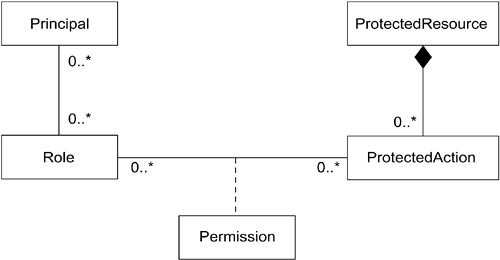
| Executable UML defines groupings of data and behavior ("classes"), the behavior over time of instances ("state charts"), and precise computational behavior ("actions"). The reason for the quotation marks is that Executable UML does not prescribe implementation. Rather, a "class" in Executable UML represents a conceptual grouping of data and behavior that may be implemented as a class, or it may be implemented as, say, a C struct and a set of associated functions or as a VHSIC Hardware Description Language (VHDL) entity. (VHSIC stands for Very High Speed Integrated Circuits.) In other words, a "class" doesn't have to be implemented as a class. Consequently, Executable UML is a software-platform-independent language that can be translated into any target. For this reason, we also use the word "translatable" as well as "executable." At system construction time, the conceptual objects are mapped to threads and processors. The generated output must maintain the desired sequencing specified in the application models. Objects may be distributed, sequentialized, even duplicated redundantly or split apart, so long as the defined behavior is preserved. In addition to successive transformation of complete models, models need to be woven together with other models to produce a system. In a banking system, the Bank model could be expressed as an executable model, but it would not solve the bank's problem until it was connected to another complete model of the Security subject matter. When linked together and translated into code, the executable models become a system. To effect this combination, we can define a mapping function. (This mapping is generally a merging or representing mapping, rather then the refining mappings that transform a model from one form to another. See Scenarios for Mappings in Chapter 5.) Specifically, we need to establish that one kind of thing in one model corresponds with another kind of thing in another model. For example, the class Customer in the Bank model corresponds with an instance of a Role in the Security model. Another example is that each Account instance in the Bank corresponds with an instance of ProtectedResource in Security. We present the domain-level class diagram for the Security model again for your reference (see Figure 9-2). Figure 9-2. Domain-level class diagram for security domain
Both of these examples are static in that a (static) class in one model becomes an instance in another. (In this sense, the Security model is "meta" to the bank application, even though they both use the same Executable UML profile.) However, mappings can be between any two kinds of identifiable entity in an Executable UML model. Signals may be mapped to function calls and vice versa; functions can map to changes in attribute values; signals can map to operation calls; actions can map to attributes. For example, there's a mapping between the Bank and Security models in that a withdraw operation must be authorized. Multiple entities may examine a customer's account balance, but only the customer may make a withdrawal. This mapping would require making Account.balance an instance of ProtectedResource and correlating each occurrence of the accessor function that accesses Account.Balance with a ProtectedAction. As another example, the bank application links to a UI. The user, a teller perhaps, has a screen that allows the customer to make a withdrawal. In the Bank model, this involves the setting of a value for an attribute, Account.Balance. The UI could have been constructed so that a field receives a signal, along with a data value, that causes it to display the value in green if it's positive and red if it's zero or negative. In this example, there's a correlation between an accessor function in the source model and a signal in the target model. Similarly, the detection of a button push in the UI could be modeled in that interface as a function (a signal generator) that maps via a callback function to the reception of a signal in the application. In this case, the correlation is between a signal generator and a signal. These "further out" examples illustrate the difference between MDA concepts and defining interfaces to components and frameworks via an API. In MDA, the interfaces between models are not defined in concrete; instead, "meta-interfaces" are exported by marking models (the subject of Chapter 6). Because mapping functions act as adapters between models, the fact that the user interface requires a signal to change the value of a field says nothing about the structure of its client. This sets MDA apart from components and their big brother, frameworks, because the "glue code" we mentioned in Chapter 1 (see Raising the Level of Reuse) is no longer embedded in low-level-of-abstraction-and-hard-to-reuse code.[1] Instead, the rules for mappings are externalized and generalized, which means that they can be applied at will to similar problems.
In any case, once these mappings are defined, we're ready to combine all of the models into a single target model from which code can be generated. (These steps can take place simultaneously.) The mechanism responsible is a model compiler, which weaves together the several models according to a single set of architectural rules. |
EAN: N/A
Pages: 134
- Chapter IV How Consumers Think About Interactive Aspects of Web Advertising
- Chapter VIII Personalization Systems and Their Deployment as Web Site Interface Design Decisions
- Chapter XIV Product Catalog and Shopping Cart Effective Design
- Chapter XV Customer Trust in Online Commerce
- Chapter XVI Turning Web Surfers into Loyal Customers: Cognitive Lock-In Through Interface Design and Web Site Usability
