3D Math 101
I'll try my best to make this topic interesting. I'll know I've succeeded if I get through writing it without losing consciousness. This stuff can make your eyes glaze over. Remember one thing: You must understand the math or you'll be hopelessly confused if you attempt any 3D programming. Sure, you'll be able to compile a DirectX sample program, tweak some parameters, and make some pretty pictures. Once you leave "Sampleland" and start writing your own 3D code, however, you won't have a freaking clue why your screen is black and none of the pretty pictures show up. You'll attempt to fix the problem with random tweaks of various numbers in your code, mostly by adding and removing minus signs, and you'll end up with the same black screen and a mountain of frustration.
My advice is to start small. Make sure you understand each component fully, and move to the next. Have patience, and you'll never tweak a negative sign in anger again.
| Gotcha | 3D programming is easier to get wrong than right, and the difficult part is that a completely miscoded system can look and feel correct. There will be a point where things will begin to break down, but by that time you might have hundreds or thousands of lines of bogus code. If something is wrong, and you randomly apply a negative sign to something to fix it, and don't understand why it fixed it, you should back up and review the math. |
Coordinates and Coordinate Systems
In a 2D graphics system you express pixel coordinates with two numbers: (x,y). These are screen coordinates to indicate that each integer number x and y corresponds to a row and column of pixels, respectively. Taken together as a pair, they describe the screen location of exactly one pixel. If you want to describe a 2D coordinate system fully, you need a little more data, such as where (0,0) is on the screen, whether the x coordinate describes rows or columns, and in which direction the coordinates grow—to the left or right. Those choices are made somewhat arbitrarily. There's nothing that says we couldn't create a 2D graphics engine that used the lower right-hand corner of the screen as our (0,0) point—our origin. There's nothing that would keep us from describing the x-axis as vertical and y as horizontal, and both coordinates grow positive toward the upper left-hand side of the screen.
Nothing would keep us from doing this, except perhaps the risk of industry-wide embarrassment. I said that these choices of coordinate system are somewhat arbitrary, but they do have a basis in tradition or programming convenience. Here's an example: Since the display memory is organized in row order it makes sense to locate the origin at the top left-hand side of the screen. Traditional Cartesian mathematics sets the horizontal as the X-axis and the vertical as the Y-axis, which means that programmers can relate to the graphics coordinates with ease. If these were reversed, programmers would be constantly slapping their foreheads and saying, "oh yeah, those idiots made the X-axis vertical!"
A 3D world requires a 3D coordinate system. Each coordinate is expressed as a triplet: (x,y,z). This describes a position in a three dimensional universe. As you might expect, a location on any of the three axes is described with a floating-point number. The range that can be expressed in a 32-bit floating-point number in IEEE format is ~10-44.85 to ~1038.53. The diameter of the known universe is on the order of 1026 meters. The smallest theoretical structures of the universe, superstrings, have an estimated length of 10-35 meters. You might believe that a 32-bit floating-point number is more than sufficient to create a 3D simulation of everything in our universe, but you'd be wrong, because even though the range is up to the task the precision is not. Oddly enough, we may one day find out that the universe is best expressed in terms of 256-bit integers, which would give enough range and precision to represent a number from 0 to ~1076, plenty to represent the known universe, ignoring irrational or transcendental numbers like π.
So where does that leave you and your 32-bit IEEE floating-point number with its decent range and lacking precision? The IEEE format stores an effective 24 bits of resolution in the mastissa. This gives you a range of 1.67 x 10⁷. How much is that? As Table 9.1 indicates, you should set your smallest unit based on your game design. Most games can safely use the 100 micrometer basis since your sandbox can be as big as downtown San Francisco. The human eye can barely detect objects 100 micrometers across, but can't discern any detail.
| Smallest Unit | Physical Description of Smallest Representable Object (as a Textured Polygon) | Upper Range In Meters | Physical Description of Area in the Upper Range |
|---|---|---|---|
| 100m | A group of redwood trees. | 1.67 x 10⁹ | Earth/Moon System |
| 1m | A human being | 1.67 x 10⁷ | North and South America |
| 1cm | A coin | 1.67 x 10⁶ | California |
| 1mm | A flea | 1.67 x 10⁵ | San Francisco Bay Area |
| 100 μm | A grain of pollen | 1.67 x 10⁴ | Downtown San Francisco |
This is why most games set their basic unit of measurement as the meter, and constrain the precision to 1mm and set their maximum range to 100 kilometers. Most art packages like 3D Studio Max allow artists to set their basic unit of measurement. If you use such a package you need to make sure they set it to the right value for your game.
| Gotcha | A common source of problems in computer game development is when artists can't seem to get their units of measurement correct. Either they'll create models with different units of measurement, such as feet instead of meters. One clue: If things in your game appear either three times too big or three times too small, your artist is using the wrong unit of measurement. |
Now that we've nailed the range and precision of the 3D coordinates, let's take a few moments to consider those arbitrary decisions about origin and axes directions. You've probably heard of 3D coordinate systems described as either left or right handed, and if you're like me you tend to forget which is which, and the explanation with your fingers and thumbs was always just a little confusing because I couldn't remember how to hold my hands! Here's another way to visualize it. Imagine that you are standing at the origin of a classic 3D Cartesian coordinate system and you are looking down the positive X-axis. The positive Y-axis points straight up. If the coordinate system is right handed, the Z-axis will point to your right. A left-handed coordinate system will have a positive Z-axis pointed to the left.
Why is handedness important? For one thing, when you move objects around your world you'll want to know where your positive Z-axis is and how it relates to the other two, or you might have things zig instead of zag. The tougher answer is that it effects the formulas for calculating important 3D equations such as a cross product. I'm extremely glad I don't have to explain a 4D coordinate system. I don't think I have it in me.
| Gotcha | Since some art packages have different handedness than 3D rendering engines, you have to know how to convert the handedness of objects from one coordinate system to another. Here how you do it:
Here's an example: Original:
Becomes:
|
Vector Mathematics
Vector and matrix math was always the sleepiest part of linear algebra for me. Rather than just show you the guts of the dot product or cross product for the umpteeth time, I'll also tell you what they do. That's more important anyway. I'll also show you some safety rules regarding matrix mathematics because they don't act like regular numbers.
Before we go any further you need to know what a unit vector is because it is something you'll use all the time in 3D graphics programming. A unit vector is any vector that has a length of 1.0. If you have a vector of arbitrary length, you can create a unit vector that points in the same direction by dividing the vector by its length. This is also known as "normalizing" a vector:
float length = sqrt ( v.x * v.x + v.y * v.y + v.z * v.z) Vector unit = Vector(v.x / length, v.y / length, v.z / length) Example: V(x,y,z) = V(3, 4, 0) Length = Sqrt ( 9 + 16 + 0 ) = Sqrt ( 25 ) = 5; Unit Vector U(x,y,z) = U( 3/5, 4/5, 0/5) = U(0.6, 0.8, 0)
When we talk about dot and cross products, their inputs are always unit vectors. The formulas certainly work on any arbitrary vector, but the results are relatively meaningless. Take the same formulas and apply unit vectors to them, and you'll find some interesting results that you can use to calculate critical angles and directions in your 3D world. A dot product of two vectors is a number, sometimes called a scalar. The cross product of two vectors is another vector. Remember these two important facts and you'll never get one confused with the other again. Another way to say this is dot products calculate angles, and cross products calculate direction. The dot product is calculated with the following formula:
float dotProduct = ( v1.x * v2.x ) + ( v1.y * v2.y ) + (v1.z * v2.z); Unit vectors never have any coordinate with an absolute value greater than 1.0. Given that, you'll notice that the results of plugging various numbers into the dot product formula have interesting effects. Here are a few:
-
V1 equals V2: If you calculate the dot product of a vector with itself, the value of the dot product is always 1.0.
-
V1 is orthogonal to V2: If the two vectors form a right angle to each other, the result of the dot product is always zero.
-
V1 points in the opposite direction to V2: Two vectors pointing exactly away from each other have a dot product of -1.0.
If this relationship between vectors, right angles, and the range [-1.0, 1.0] is stirring some deep dark memory, you're correct. The dark memory is trigonometry, and the function you are remembering is the cosine. It turns out that the dot product of two unit vectors calculates the cosine of the angle between the two vectors. Another way to visualize the dot product graphically is that the dot product projects one vector onto the other, and calculates the length of that vector. This dot product relationship is shown in Figure 9.1, where the dot product equals the length of the projection of vector A onto B. As it turns out, this length is exactly the same as the projection of vector B onto vector A. Weird, huh?
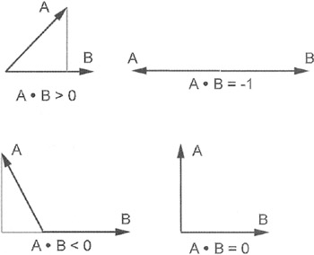
Figure 9.1: Dot Products.
The dot product can be useful by itself, since it can determine whether the angle between two vectors is acute, a right angle, or obtuse. The classic application of the dot product in 3D graphics is determining whether a polygon is facing towards or away from the camera.
In Figure 9.2, the camera has a unit vector called the "look at" vector and it points in the same direction as the camera. Each polygon has a normal vector that is orthogonal to the plane of the polygon. If the dot product between these two vectors is less than zero, the polygon is facing the camera and should be added to the draw list. In the case of Figure 9.2, the dot product for these two vectors is close to -1.0, so the polygon will be drawn.
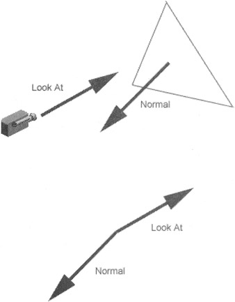
Figure 9.2: Dot Products Used for Backfacing.
If you want the actual angle represented by the dot product, you must perform an arccosine operation. If you remember those hazy trig classes at all you'll know that the arccosine isn't defined everywhere, only between values [-1.0, 1.0]. That's lucky, because dot products from unit vectors have exactly the same range. So where's the problem? The arccosine will always return positive numbers.
The dot product is directionless, giving you the same result no matter which vector you send in first: A dot B is the same as B dot A. Still not convinced this is a problem? Let's assume you are using the dot product to determine the angle between your current direction and the direction vector that points to something you are targeting.
In Figure 9.3, the white arrow is the current direction, and the grey arrows are oriented 45 degrees away about the y-axis. Notice that one of the grey arrows is pointing straight to our teapot target, but the other one is pointing in a completely wrong direction. The dot products between the white direction vector and both grey vectors are the same!
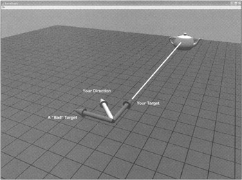
Figure 9.3: Dot Products Can't Find Targets.
Remember that the dot product measures angles and not direction. As you can see from the diagram, the dot product won't tell you which way to turn, only how much to turn. You need a cross product.
Graphically, the cross product returns a vector that is orthogonal to the plane formed by the two input vectors. The cross product vector should be normalized before you use it. Planes have two sides, and the resulting normal vector can only point in one direction. How does it know which way to point? It turns out that cross products are sensitive to the order of their input vectors. In other words, A cross B is not equal to B cross A. As you might expect, it is exactly negative. This is where the handedness of the coordinate system comes back into play. The cross product is always calculated with this formula:
cross.x = (A.y * B.z) - (B.y * A.z) cross.y = (A.z * B.x) - (B.z * A.x) cross.z = (A.x * B.y) - (B.x * A.y)
I'm going to borrow your right hand for a moment. Hold your right hand out in front of you, fingers together, and totally flat. Make sure you are looking at your palm. Extend your thumb out, keeping your hand flat. Your thumb is vector A and your forefinger is vector B. The result of the cross product, A cross B, is a vector pointing up out of your palm. If you did it backwards, B cross A, the vector would be pointing away from you. This is the fundamental difference between left and right handed coordinate systems—determining which vectors get sent into the cross product in which order. It matters!
The classic use of the cross product is figuring out the normal vector of a polygon (see Figure 9.4). The normal vector is fundamental to calculating which polygons are facing the camera, and therefore, which polygons are drawn and which can be ignored.
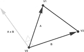
Figure 9.4: A Cross Product.
For any polygon that has three vertices, V0, V1, and V2, the normal vector is calculated using a cross product:
Vector A = V1 - V0; Vector B = V2 - V1; Vector Cross = A X B;
In a right-handed coordinate system, the vertices are arranged in a counter clockwise order as they are seen when looking at the drawn side of the polygon.
Another use is figuring the direction. Returning to our chase problem, we have a dot product that tells us that we need to steer either left or right, but we can't figure out which. It turns out that the cross product between the direction vectors will tell us.
The cross product between the target vector and your direction vector points up, indicating we should steer right (see Figure 9.5). If the cross product pointed down, the target would have been off to our left. The target example is somewhat contrived because you don't actually need the cross product at all. It makes a good example because it's a useful experiment to visualize the usefulness of the cross product. Through a little trickery, you can do it solely with the dot product, as long as you choose the correct vectors. If you use a vector that points to your right instead of straight ahead, your dot product will yield a positive number if you need to steer right and a negative number if you need to steer left, and something close to zero if your target is right in front of you. Even better, if your steering parameters range from -1.0 to steer hard left and 1.0 to lock it all the way to the right, you can send this dot product straight into your steering code. Cool, huh?
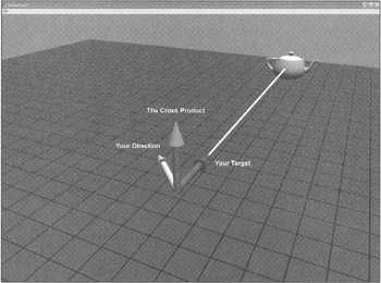
Figure 9.5: A Cross Product and A Dot Product Can Find a Target.
Matrix Mathematics
A 3D world is filled with objects that move around. It would seem like an impossible task to set each vertex and surface normal of every polygon each time an object moved. There's a shortcut, it turns out, and it concerns matrices. Vertices and surface normals for objects in your 3D world are stored in object space. As the object moves and rotates, the only thing that changes is the object's transform matrix. The original vertices and normals remain exactly the same. The object's transform matrix holds information about its position in the world and its rotation about the X, Y, and Z-axis.
Multiple instances of an object need not duplicate the geometry data. Each object instance only needs a different transform matrix and a reference to the original geometry. As each object moves the only things that change are the values of each transform matrix. A transform matrix for a 3D engine is represented by a 4x4 array of floating point numbers. The matrix elements are set in specific ways to perform translations and different rotations. For each kind of matrix, I'll show you how to set the elements yourself or how to call a DirectX function to initialize it.
A translation matrix moves vectors linearly. Assuming you have a displacement vector T, which describes the translation along each axis, you'll initialize the translation matrix with the values shown in Table 9.2.
| 1 | 0 | 0 | 0 |
| 0 | 1 | 0 | 0 |
| 0 | 0 | 1 | 0 |
| T.x | T.y | T.z | 1 |
Here's how to do the same thing in DirectX:
// Create a DirectX matrix that will translate vectors // +3 units along X and -2 units along Z D3DXVECTOR3 t(3,0,-2); D3DXMATRIX transMatrix; D3DXMatrixTranslation(&transMatrix, t.x,t.y,t.z);
Let's look at a quick example.
D3DXVECTOR4 original(1, 1, 1, 1); D3DXVECTOR4 result; D3DXVec4Transform(&result, &original, &transMatrix);
The transform creates a new vector with values (4, 1, -1, 1). The DirectX function D3DXVec4Transform multiplies the input vector with the transform matrix. The result is a transformed vector.
| Gotcha | Did you notice my underhanded use of the D3DXVECTOR4 structure without giving you a clue about its use? Matrix mathematics is very picky about the dimensions of vectors and matrices that you multiply. It turns out that you can only multiply matrices where the number of rows matches the number of columns. This is why a 4x4 matrix must be multiplied with a 4 dimensional vector. Also, the last value of that 4D vector, w, should be set at 1.0, or you'll get odd results. |
There are three kinds of rotation matrices, one for rotation about each axis. The most critical thing you must get through your math-addled brain is this: rotations always happen around the origin. What in the hell did that mean? You'll understand it better after you see an example. First, you need to get your bearings. Figure 9.6 shows an image of a teapot, sitting at the origin. The squares are one unit across. We are looking at the origin from (x=6, y=6, z=6). The Y-axis points up. The X-axis points off to the lower left, and the Z-axis points to the lower right.
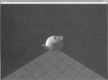
Figure 9.6: Displaying a Teapot in 3D.
If you look along the axis of rotation, an object will appear to rotate counter clockwise if you rotate it in a positive angle. One way to remember this is by going back to the unit circle in trig as shown in Figure 9.7.
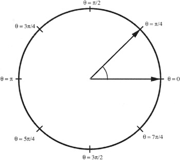
Figure 9.7: The Infamous Unit Circle.
-
A special note to my high school geometry teacher, Mrs. Connally: You were right all along—I did have use for the unit circle after all...
That means if we want to rotate the teapot so that the spout is pointing straight at us, we'll need to rotate it about the Y-axis. The Y-axis points up, so any rotation about that axis will make the teapot appear as if it is sitting on a potter's wheel. How do you calculate the angle? Go back to your unit circle to figure it out. The angle we want is 45 degrees, or π/4. We also know that the angle should be negative. Here's why: If we are looking along the Y-axis, we'd be underneath the teapot looking straight up. The teapot's spout needs to twist clockwise to achieve our desired result, so the angle is negative.
A rotation matrix for the Y-axis looks like the one shown in Table 9.3.
| cos(θ) | 0 | -sin(θ) | 0 |
| 0 | 1 | 0 | 0 |
| sin(θ) | 0 | cos(θ) | 0 |
| 0 | 0 | 0 | 1 |
Here's the code to create this matrix in DirectX:
float angle = -D3DX_PI / 4.0f; D3DXMATRIX rotateY; D3DXMatrixRotationY(&rotateY, angle);
Let's transform a vector with this matrix and see what happens. Since the teapot's spout is pointing down the X-axis, let's transform (x=1, y=0, z=0):
D3DXVECTOR4 original(1, 0, 0, 1); D3DXVECTOR4 result(0,0,0,0); D3DXVec4Transform(&result, &original, &rotateY);
Here's the result:
result {...} D3DXVECTOR4 x 0.70710677 float y 0.00000000 float z 0.70710677 float w 1.0000000 float Excellent, that's exactly what we want. The new vector is sitting on the X-Z plane, both coordinates in the positive. If we take that same transform and apply it to every vertex of the teapot, and redraw it, we'll get the picture shown in Figure 9.8.
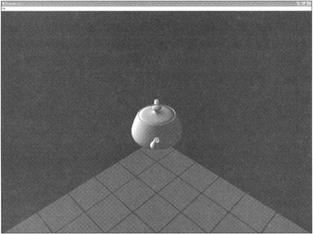
Figure 9.8: The Teapot— Rotatedt-π/4 Degrees about the Y-Axis.
Table 9.4 shows how to create a rotation about the X-axis and Table 9.5 shows how to create a rotation about the Z-axis.
| 1 | 0 | 0 | 0 |
| 0 | cos(θ) | Sin(θ) | 0 |
| 0 | sin(θ) | Cos(θ) | 0 |
| 0 | 0 | 0 | 1 |
| cos(θ) | sin(θ) | 0 | 0 |
| -sin(θ) | cos(θ) | 0 | 0 |
| 0 | 0 | 1 | 0 |
| 0 | 0 | 0 | 1 |
The DirectX code to create those two rotations is exactly what you'd expect:
float angle = -D3DX_PI / 4.0f; D3DXMATRIX rotateX, rotateZ; D3DXMatrixRotationX(…rotateX, angle); D3DXMatrixRotationZ(…rotateZ, angle);
That handles simple translation and rotation transforms. Now you need to learn how to put multiple transforms into action. It turns out that you can multiply, or concatenate, matrices. The result encodes every operation into a single matrix. I know, it seems like magic. There's one important part of this wizardry: The concatenated matrix is sensitive to the order in which you did the original multiplication. Let's look at two examples, starting with two matrices you should be able to visualize:
D3DXMATRIX trans, rotateY; D3DXMatrixTranslation(&trans, 3,0,0); D3DXMatrixRotationY(&rotateY, -D3DX_PI / 4.0f);
The translation matrix will push our teapot down the X-axis, or to the lower left in our current view. The negative angle rotation about the Y-axis you've already seen.
In DirectX, you can multiply two matrices with a function call. I'm not going to bother showing you the actual formula for two reasons. First, you can find it for yourself on the Internet and second, no one codes this from scratch. There's always an optimized version of a matrix multiply in any 3D engine you find, including DirectX:
D3DXMATRIX result; D3DXMatrixMultiply(&result, &trans, &rotateY);
Note the order. This should create a transform matrix that will push the teapot down the X-axis and rotate it about the Y-axis, in that order. Figure 9.9 shows the results.
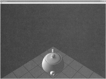
Figure 9.9: The Teapot— Rotation Applied after Translation.
If you expected the teapot to be sitting on the X-axis you must remember that any rotation happens about the origin, not the center of the object! This is a common mistake, and I've spent much of my 3D debugging time getting my matrices in the right order.
| Best Practice | Always translate last. If you want to place an object in a 3D world, you always perform your rotations first and translations afterwards. |
Let's follow my own best practice and see if we get a better result. First we reverse the order of the parameters into the matrix multiplication API:
D3DXMATRIX result; D3DXMatrixMultiply(&result, &rotateY, &trans );
Figure 9.10 shows the result.
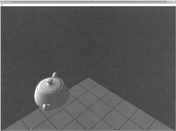
Figure 9.10: The Teapot— Translation Applied after Rotation.
I'll show you one more, just to make sure you get it. The goal of this transformation is two rotations and one translation. I want the teapot to sit four units down the Z-axis, on its side with the top towards us and the spout straight up in the air. Here's the code:
D3DXMATRIX rotateX, rotateZ, trans; D3DXMatrixRotationZ(&rotateZ, -D3DX_PI / 2.0f); D3DXMatrixRotationX(&rotateX, -D3DX_PI ); D3DXMatrixTranslation(&trans, 0,0,4); D3DXMATRIX temp, result; D3DXMatrixMultiply(&temp, &rotateZ, &rotateX); D3DXMatrixMultiply(&result, &temp, &trans);
The first rotation about the Z-axis points our teapot's spout down the negative Y-axis, and the second rotation twists the whole thing around the X-axis to get the spout pointing straight up. The final translation moves it to its resting spot on the Z-axis (see Figure 9.11).
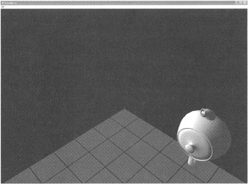
Figure 9.11: The Teapot— Two Rotations and One Translation.
I hope you've followed these bits about rotating things around an axis because it's a critical concept you need to understand before we talk about quaternions. If you think you might be hazy on the whole rotation thing, perhaps you'd better reread the previous section.
Quaternion Mathematics
Orientation can be expressed as three angles: yaw, pitch, and roll. In our teapot example yaw would be around the Y-axis, pitch would be around the Z-axis, and roll would be around the X-axis. By the way, this happens to be called the Euler representation, or Euler angles. This method has a critical weakness. Imagine you want to interpolate smoothly between two orientations. This would make sense if you had an object like an automated cannon that slowly tracked moving objects. It would know its current orientation and the target orientation, but getting from one to the other might be problematic with Euler angles.
There a special mathematical construct known as a quaternion and most every 3D engine supports its use. A quaternion is a fourth dimensional vector, and it can be visualized as a rotation about an arbitrary axis. Let's look at an example:
D3DXQUATERNION q; D3DXQuaternionIdentity(&q); D3DXVECTOR3 axis(0,1,0); float angle = -D3DX_PI / 4.0; D3DXQuaternionRotationAxis(&q, &axis, angle); D3DXMATRIX result; D3DXMatrixRotationQuaternion(&result, &q);
This code has exactly the same effect on our teapot at the first rotation example. The teapot rotates around the Y-axis, -π/4 degrees. Notice that I'm not setting the values of the quaternion directly, I'm using a DirectX API. I do this because the actual values of the quaternion are not intuitive at all. Take a look at the resulting values from our simple twist around the Y-axis:
q {...} D3DXQUATERNION x 0.00000000 float y -0.38268343 float z 0.00000000 float w 0.92387950 float Not exactly the easiest thing to read naked, is it?
The quaternion is sent into another DirectX function to create a transformation matrix. This is done because vectors can't be transformed directly with quaternions—you still have to use a transform matrix.
If you think this seems like a whole lot of work with little gain, let's look at the interpolation problem. Let's assume that I want the teapot to turn such that the spout is pointing down the Z-axis—this would mean a rotation about the Y-axis with an angle of—π/2 degrees. Let's also assume I want to know what the transformation matrix is at 2/3 of the way through the turn as shown in Figure 9.12.
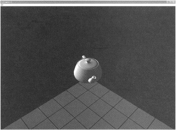
Figure 9.12: The Teapot Oriented with Quaternions.
Here's the code:
D3DXQUATERNION start, middle, end; D3DXQuaternionIdentity(&start); D3DXQuaternionIdentity(&middle); D3DXQuaternionIdentity(&end); D3DXVECTOR3 axis(0,1,0); float angle = -D3DX_PI / 2.0; D3DXQuaternionRotationAxis(&start, &axis, 0); D3DXQuaternionRotationAxis(&end, &axis, angle); D3DXQuaternionSlerp(&middle, &end, &start, 0.66f); D3DXMATRIX result; D3DXMatrixRotationQuaternion(&result, &middle);
The two boundary quaternions, start and end, are initialized in the same way. The target orientation quaternion, middle, is calculated with the DirectX method D3DXQuaternionSlerp. This creates a quaternion 66% of the way between our start and end quaternions.
I might not quite have convinced you yet but only because I used a trivial rotation that was easy to display. Face it, anyone can interpolate a rotation around a single axis. Since quaternions can represent a rotation about a completely arbitrary axis, like (x=3.5, y=-2.1, z=0.04), they can be much more useful than Euler angles.
We've just exposed the first step in getting objects to your screen. All of the matrix concatentation, quaternions, and translations you just learned were used to place a single object in a 3D world, with an orientation we wanted and the exact position we desired. This step is called transforming object space into world space. Object space is totally untransformed. The vertices exist in exactly the same spots the artist or the programmer placed them. The transform that placed the teapot exactly where we wanted it placed transformed the object space to world space, and is generally called a world transform.
In DirectX, you set the current world transform with this line of code:
pD3DDevice->SetTransform( D3DTS_WORLD, &result );
Any untransformed polygons sent into the renderer will use this transform. Your teapot will be exactly where you want it. I say untransformed polygons because it is possible to transform polygons yourself, and have the renderer do its magic with polygons in screen space. We'll learn more about that in a moment.
First, there are two more transforms to add into the mix. The addition of these two transforms is what you'll need to set a camera in the world to view the teapot and project its vertices onto a flat pane of glass—your computer's display. The first one is the view transformation.
View Transformation
If we are going to render the scene we need to have a camera. That camera must have an orientation and a position just like any other object in the world. Similar to any other object, the camera needs a transform matrix that converts world space vertices to camera space.
Calculating the transform matrix for a camera can be tricky. In many cases you want the camera to look at something, like a teapot. If you have a desired camera position and a target to look at, you don't quite have enough information to place the camera. The missing data is a definition of the up direction for your world. This last bit of data gives the camera a hint about how to orient itself. The view matrix for our previous teapot experiment used a DirectX function, D3DXMatrixLookAtLH:
D3DXMATRIX matView; D3DXVECTOR3 vFromPt = D3DXVECTOR3( 6.0f, 6.0f, 6.0f ); D3DXVECTOR3 vLookatPt = D3DXVECTOR3( 0.0f, 0.0f, 0.0f ); D3DXVECTOR3 vUpVec = D3DXVECTOR3( 0.0f, 1.0f, 0.0f ); D3DXMatrixLookAtLH( &matView, &vFromPt, &vLookatPt, &vUpVec ); m_pd3dDevice->SetTransform( D3DTS_VIEW, &matView );
By the way, the LH at the end of the DirectX function's name is a hint that this function assumes a left-handed coordinate system. There is a right-handed version of this, and most other matrix functions, as well.
The from point was out along the positive values of X, Y, and Z, and the look-at point was right back at the origin. The last parameter defines the up direction. If you think about a camera as having an orientation constraint similar to a camera boom like you see on ESPN, it can move anywhere, pan around to see its surroundings, and pitch up or down. It doesn't tilt, at least not normally. This is important, If tilting were allowed in constructing a valid view transform, there could be many different orientations that will satisfy your input data.
| Gotcha | This system isn't completely perfect because there are two degenerate orientations. Given the definition of up as (x=0, y=1, z=0) in world space, the two places you can't easily look is straight up and straight down. You can construct the view transform yourself quite easily but don't expect the look-at function to do it for you. |
Remember that the camera's view transform is a matrix, just like any other. You don't have to use the look-at function to calculate it, but it tends to be the most effective camera positioning function there is.
Projection Transformation
So far, we've taken vertices from object space and transformed them into world space, and taken world space and transformed them into camera space. Now we need to take all those 3D vertices sitting in camera space and figure out where they belong on your computer screen, and which objects sit in front of other objects.
Imagine sitting in front of a computer screen, and seeing four lines coming from your eyeball and intersecting with the corners of the screen. For he sake of simplicity I'll assume you have only one eyeball in the center of your head. These lines continue into the 3D world of your favorite game. You have a pyramid shape with the point at your eyeball and its base somewhere out in infinity somewhere. Clip the pointy end of the pyramid with the plane of your computer screen, and form a base of your pyramid at some arbitrary place in the distance. This odd clipped pyramid shape is called the viewing frustum. The shape is actually a cuboid, since it is topologically equivalent to a cube, although cruelly pushed out of shape.
Every object inside this shape, the viewing frustum, will be drawn on your screen. The projection transformation takes the camera space (x,y,z) of every vertex and transforms it into a new vector that holds the screen pixel (x,y) location and a measure of the vertices' distance into the scene.
Here's the code to create the viewing frustum of the teapot experiments:
D3DXMATRIX matProj; FLOAT fAspect = ((FLOAT)m_d3dsdBackBuffer.Width) / m_d3dsdBackBuffer.Height; D3DXMatrixPerspectiveFovLH( &matProj, D3DX_PI/4, fAspect, 1.0f, 100.0f ); m_pd3dDevice->SetTransform( D3DTS_PROJECTION, &matProj );
The DirectX function that helps you calculate a projection matrix—something you don't want to do by yourself—accepts four parameters after the address of the matrix:
-
Field of view: Expressed in radians, this is the width of the view angle. π/4 is a pretty standard angle. Wider angles such as 3π/4 make for some weird results. Try it and see what happens.
-
Aspect ratio: This is the aspect ratio of your screen. If this ratio were 1.0, the projection transform would assume you had a square screen. A 640x480 screen has a 1.333 aspect ratio.
-
Near clipping plane: This is the distance between your eye and the near view plane. Any object closer will get clipped. The units are usually meters, but feel free to set them to whatever standard makes sense for your game.
-
Far clipping plane: The distance between your eye and the far clipping plane. Anything farther away will be clipped.
| Gotcha | Don't set your far clipping plane to some arbitrarily large number in the hopes that nothing in your huge 3D world will get clipped. The tradeoff is that the huge distance between your near and far clipping plane will create sorting problems in objects close to the camera. These weird sorting problems manifest themselves as if two polygons were run through a paper shredder, since the individual pixels on two coincident polygons will sort incorrectly. If you see this problem, check your far clipping plane distance. Also, don't set your near clipping plane to zero, in the hopes that you'll be able to see things very close to the camera. There's a relationship between the near clipping plane and the field of view: If you arbitrarily move the near clipping plane closer to the camera without changing the field of view, weird things begin to happen. My suggestion is to write a little code and see for yourself. |
- An Emerging Strategy for E-Business IT Governance
- Assessing Business-IT Alignment Maturity
- Linking the IT Balanced Scorecard to the Business Objectives at a Major Canadian Financial Group
- Measuring and Managing E-Business Initiatives Through the Balanced Scorecard
- Governance Structures for IT in the Health Care Industry