4.7 Flow Models
4.7 Flow Models
Another method to help describe flows in the network is to compare them with general, well-known flow models. Flow models are groups of flows that exhibit specific, consistent behavior characteristics. The flows within a flow model apply to a single application. Directionality, hierarchy, and interconnectivity are the primary characteristics of flow models. Directionality describes the preference (of lack thereof) of a flow to have more requirements in one direction than another. Hierarchy and interconnectivity are based on the definitions from Chapter 1.
Although network architectures and designs typically treat traffic flows as having equal requirements in each direction, we are finding that many flows (especially from newer applications) have substantially different requirements in each direction. Most flows are asymmetric, and some of the newer access and transmission technologies (such as digital subscriber loop [xDSL] or ATM) can be optimized for such flows.
Flow models help describe the degrees of hierarchy and interconnectivity of flows for applications. They show where flows combine, where they can be grouped, and where flows occur between peers, which are devices at the same level in the hierarchy. They also can help us identify which flows are critical flows, which, as you may recall, are considered more important than others because they are higher in performance; have strict requirements; or serve more important users, applications, and devices.
Flow models can also be useful to help quickly identify and categorize flows in an environment so that we may easily recognize its flow characteristics. In this way, they are like application groups, discussed in Chapter 2.
We will examine the following flow models:
-
Peer-to-peer
-
Client-server
-
Hierarchical client-server
-
Distributed computing
For each model, we will consider the directionality and hierarchy of its flows. In addition, when possible, we will identify which flows in each model are critical, or important, flows.
These flow models are a subset of many possible models that you could use to characterize the flows for your network. We could include, for example, real-time (or near-real-time or interactive) flows as a model, as well as streaming media. You are encouraged to develop an exhaustive list of flow models for your network projects.
4.7.1 Peer-to-Peer
Our first flow model, peer-to-peer, is one in which the users and applications are fairly consistent throughout the network in their flow behaviors. They are, in effect, peers; that is, they act at the same level in the hierarchy. Since they (users and/or applications) are fairly consistent, their flows are also fairly consistent. Thus, we can consider the flows in a peer-to-peer flow model to be equivalent (Figure 4.21). This has two important implications:
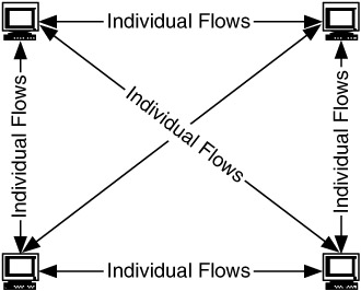
Figure 4.21: Peer-to-peer flow model.
-
We cannot distinguish between flows in this model. Therefore, either all of the flows or none of the flows are critical.
-
The flows are equivalent, so they can be described by a single specification (i.e., profile).
There are several examples of peer-to-peer flow behavior. The first is the early Internet, a portion of which is shown in Figure 4.22. In the early Internet, applications such as FTP and telnet were predominant, and each device on the network was a potential source and destination of the flows for these applications.
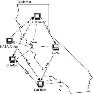
Figure 4.22: Example of peer-to-peer flows in the early Internet.
Another example is of file-sharing applications on the Internet. Basically, anywhere devices communicate directly with each other is considered peer-to-peer.
The peer-to-peer flow model is our default model when we do not have any other information about the flows in our network. In a sense, it is part of the degenerate case for our requirements map (since no flow-specific requirements can be determined). This flow model can also be used to describe flows when all users in a group need equal access to each other for an application. In addition to the file-sharing and remote access applications already described, this could also be a multimedia, tele*services application (e.g., teleseminars, telelearning, teleconferencing), in which any of the participants may source/sink data to/from any other participant. Although each of the tele*services listed can be considered a one-to-many application, there are components of each that can be applied as a set of one-to-one conversations. For example, while telelearning consists of a number of users (students) receiving and transmitting from and to a teacher, another component to this application is the ability to have side conversations between students. This part of the application is peer-to-peer (Figure 4.23).
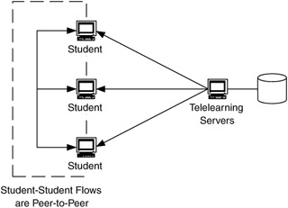
Figure 4.23: Peer-to-peer flows in a telelearning environment.
This flow model is useful in that it indicates that a performance profile may be used for those flows and that there are no (or several) critical flows for that application.
4.7.2 Client-Server
The client-server flow model is currently the most generally applicable model. This model has both directionality and hierarchy. Flows in this model are bidirectional, between clients and the server, in the form of requests and responses. This flow model is client-server because the flows are asymmetric and hierarchically focused toward the client. Thus, requests tend to be small compared with responses. Depending on the type of application, the flows may be considered almost unidirectional, from the server to the clients. Figure 4.24 illustrates the client-server flow model.
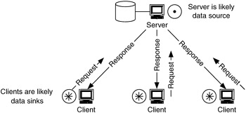
Figure 4.24: Client-server flow model.
Since the flows in the client-server model are asymmetric, with the predominant or important flows in the direction from the server to the clients, the server can be considered a data source and the clients data sinks. The server would be shown as a data source on the requirements map, with flows generating from it to its clients on other areas of the map. Since the predominant or important flows are from the server to the clients, these are the critical flows for this model. When there is a requirement to transmit information to multiple clients concurrently, multicasting at some layer in the network will need to be considered to optimize flows for this model.
This model is the traditional view of client-server operations, exemplified by ERP applications like SAP, as well as e-commerce applications. Applications such as these are highly dependent on network performance when they are configured to work across significant distances, such as when a company is dispersed across multiple locations, spanning cities, states, or countries. If the network does not properly support client-server applications, the customer will have to resort to distributing the clientserver architecture (e.g., distributed ERP), which can be expensive.
An example of a client-server flow model is in video editing. A video server can store video to be edited, and clients make requests to that server for video to edit. The server passes video to the clients, which may be sent back to the server upon completion or may be sent elsewhere for more processing (Figure 4.25).
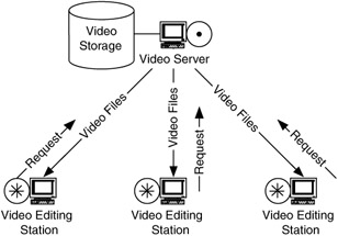
Figure 4.25: Example of client-server flows.
Another view of client-server flows is with Web applications. Although the early Internet started with peer-to-peer flows from applications such as FTP and telnet, this usage evolved to become more client-server like with the use of FTP servers, followed by applications such as gopher and Archie. Now, with the widespread use of Web applications, many flows in the Internet are between Web servers and their clients. As TCP/IP assumes more network operating system (NOS) roles, print and file services across enterprise networks and the Internet will become more client-server-oriented. For example, in the early days, a person who wanted to access information from an organization would have used the application FTP to a known site to download information. This changed into accessing an FTP or gopher server, then to accessing a Web server. Today, a person may access large quantities of information from an organization without ever entering that organization's network by gaining access through external Web servers.
However, a better flow model for Web traffic has multiple levels of tiers, with traffic flows within some of the tiers. This is the hierarchical client-server model, described in the following section.
4.7.3 Hierarchical Client-Server
As the flows within a client-server flow model become more hierarchical, in terms of adding layers, or tiers, to the flows, their behavior can be represented as a hierarchical client-server flow model. A hierarchical client-server flow model has the characteristics of a client-server flow model but also has multiple layers, or tiers, between servers. In this model there may also be flows from a server to a support server or management device, as shown in Figure 4.26. These flows (server-to-server and server-to-manager) may be considered critical, in addition to the server-to-client flows. With the additional layer(s) of hierarchy in this model, the servers can now be either data sources or data sinks (or both). More information may be needed about the application(s) to determine the status of these servers. This model is important because it recognizes server-to-server and server-to-manager flows.
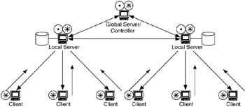
Figure 4.26: Hierarchical client-server flow model.
A hierarchical client-server flow model is indicated when multiple applications work together and share information to accomplish a task or when multiple client-server applications (or multiple sessions of the same client-server application) are managed by a higher-level application. An operations support system managing several back-office applications may often be modeled in this fashion.
Critical flows for this model are dependent on application behavior. If the applications are inherently client-server and the servers are there merely to support multiple sessions, then the client-server flows may be the only critical flows. However, when the servers communicate with each other (e.g., to update a common database or share data between applications), then the server-to-server flows may be critical, possibly in addition to the client-server flows. And when there is communication to a manager (e.g., to synchronize processing or information), the server-to-manager flows may also be critical.
We have shown that the Internet has evolved from an early peer-to-peer flow model to a client-server flow model with the acceptance of Web applications. As client-server traffic has grown, however, Web servers have been replicated and distributed across the Internet, resulting in an increase in server-to-server flows. This is being done to increase the effectiveness of Web access, in part by spreading access across multiple devices and in part by locating devices closer to the access portion of the Internet, thus bypassing part or all of the core. As a result, the Internet is evolving into a more hierarchical client-server flow model.
Such hierarchical Web services are shown in Figure 4.27. In this figure, content-distribution networks (CDNs) and mirrors (introduced in Chapter 1) are used to migrate Web content between servers and provide local access to content for users.
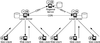
Figure 4.27: Web services modeled using hierarchical client-server flow model.
In Figure 4.27 the servers can provide the same function or different functions. For example, Web-based three-tier application servers can run application and Web services on the same device while running database services on another device. In this case the flows between servers (application/Web and database) are critical for operation.
This type of flow model can also be seen with the visualization application group described in Chapter 2. An example of this is in the visualization of scientific simulations. Consider the simulation of a multipart problem. These can be found in climate modeling, fluid flow analysis, structural analysis, and others. In climate modeling there may be a simulation consisting of multiple parts—atmosphere, earth, and ocean, as shown in Figure 4.28.
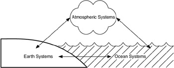
Figure 4.28: Components of a climate-modeling problem.
Each part of the simulation in Figure 4.28 may be developed on a separate computing device, probably at different locations (based on where the various scientists are located). Since each component affects the others, at the boundaries between atmosphere, earth, and ocean, data must be passed between the computing/visualization servers for each part. The flows would look like those in Figure 4.29.
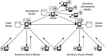
Figure 4.29: Hierarchical client-server model for scientific visualization.
In Figure 4.29, if the parts of the simulation are being solved at different locations, then the server-to-server flows may cross long (WAN) distances, affecting both LANs and WANs.
4.7.4 Distributed Computing
The distributed-computing flow model, shown in Figure 4.30, is the most specialized of the flow models. A distributed-computing flow model can have the inverse of the characteristics of the client-server flow model or can be a hybrid of peer-to-peer and client-server flow models. In this model, flows may be primarily between a task manager and its computing devices (like a client-server model) or between the computing devices (like a peer-to-peer model). The type of model depends on how the distributed computing is done.
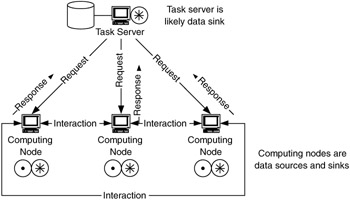
Figure 4.30: Distributed-computing flow model.
The important characteristics of this model are that the flows can be client-server but are reversed in direction and that the computing devices may have strict performance requirements.
We can make distinctions in the distributed-computing flow model based on the relationship between the task manager and the computing devices and what the task is. This relationship can result in the computing devices being closely coupled, where there are frequent transfers of information between devices, or loosely coupled, where there may be little to no transfer of information between computing devices. Tasks may range from having a coarse granularity, where each task is dedicated to a single computing device, to having a fine granularity, where a task is subdivided between several devices and the computing is done concurrently.
When the task has a coarse granularity and the computing device relationship is loosely coupled, the distributed-computing flow model takes the form of a computing cluster or computing resource management system, where tasks are allocated to each computing device based on resource availability. Thus, each computing device communicates with the cluster server or resource manager. Figure 4.31 shows the flows for an example of a computing cluster.
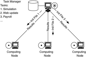
Figure 4.31: Flows for a computing cluster.
The flows in this type of distributed-computing flow model are similar to those in the client-server flow model, in which communications are primarily between each client and the server. A difference here is that the direction of the flows is not necessarily from the computing server to its clients. In fact, the size of the task initialization file (which is, in a sense, a request) sent from the server to each computing device may be much smaller than the size of the results of the computation, which is sent from the computing device to the server. In this model the flow directionality is asymmetric, but in the opposite direction from the client-server flow model. Also, each of the flows between the computing devices and their server is independent of the other flows. There is no synchronization between individual flows. The critical flows for this model are from the computing devices to their server. Since the flows for this model are asymmetric, toward the server, the server acts as a data sink and the computing devices act as data sources.
When the task has a fine granularity and the computing node relationship is closely coupled, the distributed-computing flow model behaves like a simplified parallel processing system, whereby each task is subdivided based on degree of parallelism in the application and topology of the problem, between several computing devices. These devices work concurrently on the problem, exchanging information with neighbor devices and expecting (and waiting for) updated information. The task manager set up the computing devices and starts the task with an initialization file, as in Figure 4.32.
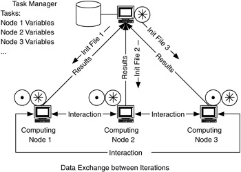
Figure 4.32: Flows for parallel computing.
Flows in this type of distributed-computing flow model can have the most stringent performance requirements of any of the models. Since computing devices may block (halt their computations) while waiting for information from neighbor devices, the timing of information transfer between computing devices becomes critical. This has a direct impact on the delay and delay variation requirements for the network connecting the devices. Although each individual flow has directionality, collectively there is little or no overall directionality. Individual flows in this model can be grouped to indicate which neighbor devices a computing device will communicate with for a given problem or topology. For example, a problem may be configured so that a computing device will communicate with one, two, four, or six of its closest neighbors.
For this model, critical flows are between computing devices. When a device will transfer the same information to several neighbors simultaneously, multicasting should be considered to optimize flow performance. There are not clear data sources or sinks for this model. The climate-modeling problem shown in Figure 4.28 could also be considered with a distributed-computing flow model, depending on the task granularity and degree of coupling within the system.
Flow requirements will vary between the computing cluster and parallel system models, depending on the degrees of coupling and granularity in the task. Depending on the application and amount of analysis you want to put into this model, you can use the computing cluster and parallel system models as they are or you can modify the task granularity and degree of coupling to suit your needs.
EAN: 2147483647
Pages: 161