The Layered Troubleshooting Approach
Networks are based on the Open System Interconnection (OSI) model of networks, which is a layered architecture used to design networks compatible with all types of operating systems. The OSI model contains seven layers, which are organized in the order of their role for facilitating data transfer. In addition to the OSI model, another model that is widely used as a standard for internetwork communication is the Transmission Control Protocol/Internet Protocol (TCP/IP) model. This model has a four-layered architecture, and each layer corresponds to one or more layers of the OSI model. The functions of these layers are similar to those performed by the layers of the OSI model.
Because most networks are based on the layered architecture of OSI or the TCP/IP model, the troubleshooting approach applied to such networks is called the layered troubleshooting approach. Using the layered approach, you can isolate and troubleshoot problems pertaining to a specific layer. As a result, other layers are not affected, and troubleshooting is carried out on only that area of the network where the problem has occurred; the rest of the network functions without any interruption. In addition, the layered troubleshooting approach allows for easy and quick identification of the type of error or problem.
The layered troubleshooting approach provides various advantages as compared to the general troubleshooting methods. The following are the main advantages of the layered troubleshooting approach:
-
Sequential analysis and identification of the problem
-
Easy identification of the possible problem areas, because the function of each layer is predefined
-
Facilitation of improvement of network performance
To understand the troubleshooting of networks based on the OSI or TCP/IP models, you need to understand the layered architecture of both these models.
The Layered Architecture of the OSI Model
The OSI model is a collection of seven layers:
-
Physical
-
Data-link
-
Network
-
Transport
-
Session
-
Presentation
-
Application
Each layer performs a specific set of functions that are required to transfer data between hosts. In addition, to facilitate smooth data transfer, each layer provides services to the layer above and below it. Figure 1.4 shows a simple diagrammatic representation of the position and appearance of these layers in the OSI model.
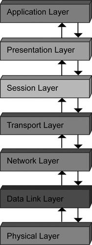
Figure 1.4: Position of layers in the OSI model.
Each layer is connected to the layer above and below it through an interface, which enables the layers to interact and communicate with each other. For example, the interface between the Application and Presentation layers is called the application-presentation interface. The OSI model states that data flowing from source to destination must always pass through each layer of the model at both ends. Figure 1.5 displays the flow of data from source to destination.
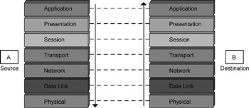
Figure 1.5: The data movement from source to destination in the OSI model.
In Figure 1.5, consider A as the source and B as the destination. According to the OSI model, any data starting from the Application layer of source A will travel up to the Physical layer. After reaching the Physical layer of destination B, the data moves up to the Application layer of B. At each layer, the data or message is modified according to the functionality of each layer. During the entire process, each layer of source A will communicate only with the corresponding layer of destination B. This means that the Presentation layer of A will communicate with the Presentation layer of B, and the Session layer of A will communicate with the Session layer of B, and so on.
The benefits of a layered protocol model are:
-
Easy to troubleshoot, because each layer performs a specific function
-
Interoperability of products from different vendors
-
Ease in modifying programming interfaces
-
Simplified troubleshooting
-
Enhanced compatibility between diverse systems
-
Future upgrade of a single layer does not affect other layers
Physical Layer
The Physical layer transmits bit streams of data over a physical medium from one host to another. The Physical layer encodes bit streams of 1s and 0s to signals before transmitting data. In addition, the Physical layer decides the line configuration and topology (ring, star, or mesh) of hosts connected in the network and defines the transmission mode (simplex, half-duplex, or full-duplex) between hosts.
Data-Link Layer
The Data-link layer enables node-to-node delivery of data in a network by converting bit streams received from the Network layer into manageable units. These units are called frames. A header is added to each frame to generate the physical address of the source and destination nodes. To maintain consistent rates of data transmission between the source and destination, the Data-link layer applies the flow control mechanism. This mechanism is a precautionary measure to ensure that the bit stream sent by a fast source node does not flood the destination node.
Network Layer
The Network layer manages internetworking and communication across multiple networks connected through routers and gateways. The Network layer handles the delivery of data from the source to the destination host. In addition, it facilitates delivery of data packets across multiple networks by generating the logical address of the data packet to be delivered. This provides easy identification of a data packet when it is transmitted across networks.
Transport Layer
The Transport layer enables delivery of data packets to the specific application running on the destination host. The Transport layer divides a data packet into data segments of uniform size, to which it assigns sequence numbers. Each sequence number identifies the segment and the associated data packet. The sequence number can identify the data packets that are lost or corrupted during transmission. The Transport layer also applies flow, connection, and error control mechanisms to a data packet.
The Transport layer implements two types of connection controls: connectionless and connection-oriented. In connectionless control, the Transport layer treats each data segment as a separate message, which is delivered to the Transport layer of the destination network. However, in connection-oriented control, the Transport layer of the source network first establishes a connection with the Transport layer of the destination network, then transmits the data segments. Thereafter, the connection between the two Transport layers is terminated.
Session Layer
The Session layer is the network dialog controller that establishes, maintains, and synchronizes interaction among networks. The layer first establishes a session between the source and the destination networks, which may be either in half-duplex or full-duplex mode. The Session layer then adds checkpoints to the data being transmitted.
| Note | In half-duplex transmission, you can either transmit or receive data at a single instance, whereas in full-duplex transmission, you can simultaneously transmit and receive data. |
Presentation Layer
The Presentation layer is responsible for the syntax and semantics of the data being transferred. The Presentation layer is concerned with all aspects pertaining to the presentation of the data packets being transmitted. It translates the data being transferred into a format understandable to the destination node, encrypts the data packets to prevent data corruption and hacking, and compresses the data packets for smooth transmission.
Application Layer
The Application layer is the uppermost layer of the OSI Model. This layer handles high-level protocols such as HTTP, FTP, and SMTP. The Application layer uses these protocols to communicate with the application on the destination system. In addition, this layer handles flow control and error recovery.
Table 1.1 lists the different protocols running on each layer of the OSI model.
| Layer | Standards/Protocols/Applications |
|---|---|
| Application | DNS |
| FTP and TFTP | |
| BOOTP | |
| SNMP and SMTP | |
| MIME | |
| NFS | |
| FINGER | |
| TELNET | |
| NCP | |
| APPC | |
| AFP | |
| SMB | |
| Presentation | PICT |
| TIFF | |
| MIDI | |
| MPEG | |
| Session | NetBIOS |
| NFS | |
| RPC | |
| Mail Slots | |
| DNA SCP | |
| Names Pipes | |
| Transport | TCP |
| SP | |
| NetBIOS/NetBEUI | |
| ATP | |
| ARP, RARP | |
| NWLink | |
| Network | IGMP |
| IPX | |
| NetBEUI | |
| OSI | |
| DDP | |
| IP | |
| ARP | |
| RARP | |
| ICMP | |
| RIP | |
| OSFP | |
| IGMP | |
| DECnet | |
| X.25 | |
| Data-link | HDLC |
| SDLC | |
| LAPB | |
| PPP | |
| ISDN | |
| SLIP | |
| Physical | IEEE 802 |
| IEEE 802.2 | |
| EIA/TIA-232 | |
| EIA-530 | |
| ISDN | |
| RS232 | |
| ATM |
The Layered Architecture of the TCP/IP Model
TCP/IP is the most widely used networking protocol on the Internet. Both TCP and IP work together to facilitate safe and fast delivery of data through a network. To increase the transmission speed of large blocks of data, the data is split into smaller data fragments. These fragments are called data packets. TCP/IP plays a pivotal role in this context. TCP affixes a header to the data packet, which contains information pertaining to the destination address, source address, and length of the data. The role of IP is to ensure that once the data packets reach the destination address, they are reassembled into the original data block, and sent for use by the intended application. TCP/IP is a condensed version of the OSI model and has fewer layers. Figure 1.6 displays the layered architecture of the TCP/IP model.
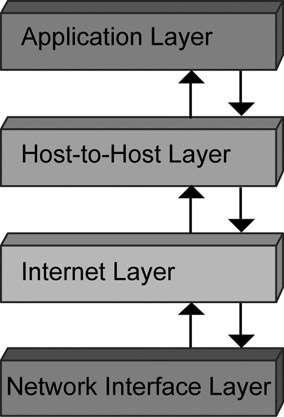
Figure 1.6: The layered architecture of the TCP/IP model.
As shown, the TCP/IP model consists of four layers:
-
Network Access layer
-
Internet layer
-
Transport layer
-
Application layer
Network Access Layer
The Network Access layer is placed at the bottom of the TCP/IP model hierarchy. The functions provided by the Network Access layer include encapsulating IP datagrams into frames and mapping IP addresses with physical devices.
All the processes in the Network Access layer are carried out by software applications and drivers customized to suit individual parts of hardware. Configuration often involves selecting the required driver for loading and selecting TCP/IP as the protocol.
Internet Layer
The Internet layer lies immediately below the Transport layer and above the Network Access layer of the TCP/IP model. The operating protocol of this layer is Internet Protocol (IP). The Internet Protocol builds the foundation of the packet delivery system, which serves as the basis for the entire concept of TCP/IP networking. This protocol manages connections over networks when data packets are transferred from the source to the destination.
IP is a connectionless protocol, which means it does not provide features such as a source-to-destination control of communication flow. IP relies on other layers and their associated protocols to provide this feature. Even functions such as error detection and correction in data packets are executed by other layers. In this context, IP is sometimes thought to be an unreliable protocol, though this does not imply that IP is not to be relied upon to deliver data via a network. It means that IP itself does not execute error checking and correcting functions. All information that flows through the TCP/IP networks uses the Internet Protocol.
Transport Layer
The Transport layer lies between the Application and Internet layers of the TCP/IP model. The two primary protocols associated with this layer are the Transmission Control Protocol (TCP) and the User Datagram Protocol (UDP).
TCP is a connection-based protocol, which enables error detection and correction in the data packets. It also ensures reliable delivery of data packets from source to destination. UDP is a connectionless and faster protocol as compared to TCP. It has low overhead costs and time associated with it, because it provides quick transfer of data. However, it does not provide the error detection and correction features of TCP.
The selection of protocols in the Transport layer is dependent on end user needs. TCP is used if a reliable connection session with two-way communication of data is of paramount importance. UDP is used to develop applications that are low on overheads.
Application Layer
The Application layer is the top layer of the TCP/IP reference model. It includes both the Presentation and Session layers of the OSI model. The word application is used to define any process that takes place above the Transport layer. The Application layer encompasses all processes that use the Transport layer protocols and transfer data to the Internet layer.
Mapping the TCP/IP and OSI Models
The TCP/IP suite of protocols works in Layers 3 and 4 of the OSI model. TCP/IP is made up of two protocols: TCP and IP. TCP/IP is the protocol used for communication over the Internet. Besides working in Layers 3 and 4, TCP/IP also has specifications for applications such as mail and FTP. Figure 1.7 depicts the mapping of the OSI and TCP/IP models.
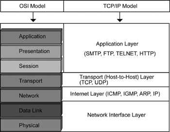
Figure 1.7: Mapping the OSI and TCP/IP models.
Using the Layered Approach
Using the layered approach, you can troubleshoot problems pertaining to each layer separately. Let us understand the different problems that occur on each layer of the OSI model and their possible solutions.
Troubleshooting Problems on the Physical Layer
The Physical layer of the OSI model is concerned with the transmission of the stream of data in bits. Data transmission between networks takes place through the Physical layer. This transmission takes place using various transmission media, such as:
Magnetic media: Physically transmits data from one host to another. Magnetic transmission media provides maximum bandwidth for data transmission and can be reused multiple times to transmit data. But magnetic media are prone to destruction, both accidental or due to natural calamity. Examples of magnetic media are floppy disks and cassette tapes.
Twisted pair cables: Pairs of copper wires that are twisted to reduce electrical interference from other twisted pair cables placed alongside. Twisted pair can transmit data across long distances with the help of repeaters. In addition, the bandwidth provided by twisted pair depends upon the thickness of the cable and the distance it must travel. The most common application of twisted pair cables is the telephone system.
Coaxial cable: Copper wire cable protected from changes in temperature by an insulating material and a conducting material. Coaxial cable provides high bandwidth and can facilitate high-speed data transmission for longer distances than twisted pair cables.
Fiber optics: Uses light signals to transmit data over long distances without using repeaters.
| Note | Coaxial cables are of two types: baseband and broadband. Baseband coaxial cable is of 50 ohm and transmits digital data; broadband cable is of 75 ohm and transmits analog data. (Ohm is the unit for resistance.) |
Problems of the Physical layer are related to the choice of the transmission media, which depends on the amount, distance, and rate of data transmission.
If data needs to be transmitted in small blocks, over a short distance, and frequency of data transmission is less, twisted pair or coaxial cable can be used. However, if large blocks of data are to be transmitted over a long distance and with high frequency, optical fiber should be used.
Apart from this, data can be transmitted across the networks using wireless media such as radio, infrared, and microwave transmission. These transmission media provide connectivity to mobile users. Unlike static transmission media, wireless media provide long-distance communication and data transmission, which spans continents across the globe.
The Physical layer also deals with the frequency and bandwidth problems of the data being transmitted. The Physical layer applies multiplexing, such as time-division and frequency-division multiplexing, to overcome problems related to optimizing bandwidth of the transmission media.
Troubleshooting Problems on Data-Link Layer
The Data-link layer of the OSI model provides the Network layer with a well-defined interface, groups the bits transmitted to the Physical layer into frames, identifies transmission errors, and applies flow control mechanisms that prevent a slow receiver from being flooded with data sent by a fast transmitter. For providing all these services, the layer uses mechanisms, such as Cyclic Redundancy Check (CRC), for error detection and flow control.
However, the main function of the Data-link layer is to ensure delivery of data from the Network layer of the source host to the Network layer of the destination host. While performing these functions, it is possible for the data to become corrupted or lost. To counter this problem, the Data-link layer uses the following protocols:
Unrestricted Simplex Protocol: Assumes that the data is transmitted in only one direction and Network layers of the source and destination networks are functional. This protocol is unreliable because there is always some loss of data during transmission.
Simplex Stop-and-Wait Protocol: Assumes that the receiving Data-link layer stores the data frames until these are transmitted to the Network layer. In addition, this is a simplex protocol, which assumes that the communication channel is error free. The disadvantage of implementing this protocol is that it does not provide the recipient node any mechanism to prevent overflow of data.
Sliding Window Protocol: Uses a single channel to transmit control and data frames to keep track of the data frames being transmitted. It was introduced to provide bi-directional data communication and transmission.
The Data-link layer also uses various error-detection techniques, such as CRC and bit stuffing, to detect transmission errors that corrupt the data frames. In addition, the Data-link layer applies a flow control mechanism to prevent a fast sender from flooding a slow receiver with data frames.
Troubleshooting Problems on the Network Layer
The main function of the Network layer is to deliver data packets from the source to the destination network using routers, switches, and bridges. The problems that the Network layer might encounter include:
-
Overloading of a specific transmission route
-
Inappropriate subnet topology
-
Dependency of the Network layer on the subnet topology and its number
-
Network congestion
To counter these problems, the subnet topology should be independent of the Network layer. Similarly, routing algorithms should be used to ensure proper routing of the data packets from the source to the destination network. Examples of routing algorithms include flooding, shortest path routing, and flow based routing.
In the flooding routing algorithm, each data packet is sent to every router. This results in the creation of multiple data packets. In the shortest path routing algorithm, a graph is created to identify the shortest path between the source and destination.
Both the flooding and the shortest path routing algorithm are based on the topology of subnets but do not take into account the load on each router. As a result, these routing algorithms do not provide accurate results. To ensure accurate results with respect to selecting the appropriate router, the anticipated load on the router needs to be considered. This is done by using the flow-based routing algorithm, which identifies the shortest route between the source and destination networks with minimum data transmission load.
Network congestion hampers smooth flow of data and may corrupt the data packets being transmitted. The Network layer applies congestion control algorithms to counter the problems of network congestion. These congestion control algorithms monitor the network to detect the probable areas where network congestion can occur and apply corrective action to reduce the congestion.
Troubleshooting Problems on the Transport Layer
The Transport layer is the core of the OSI model, because it serves as a bridge between the lower and upper layers to ensure reliable data transmission. The Transport layer can encounter the following problems:
-
Unreliable connection between source and destination networks
-
Unprotected transmission of data packets
-
Data transmission delay
-
Priority of data packets to be transmitted
-
Problems with error detection and correction
-
Flooding the slow receiver with data packets
To overcome the above-mentioned problems, the Transport layer uses the three-way handshake protocol. In this protocol, the source host sends a connection request to the destination host. If the destination host is ready to receive data packets, it sends a connection acknowledgment signal to the source host. After receiving the connection acknowledgment signal from the destination host, the source host sends the data packet to the destination host.
On receipt of the data packet, the destination host sends an acknowledgment signal to the source host. If the transmitted data packet is lost during transmission, the destination host does not send an acknowledgment signal to the source host.
In such a situation, the source host resends the data packet after a stipulated period. Using this protocol, the Transport layer provides retransmission of the lost or corrupted data packets.
Troubleshooting Problems on the Application Layer
The Application layer generally encounters problems pertaining to data security during transmission. To protect data from unauthorized access and hacking during transmission, the Application layer applies various encryption techniques. The types of encryption techniques are private key encryption and public key encryption.
To implement private key encryption, the Network layer uses algorithms such as Data Encryption Standard (DES). In the DES algorithm, the data contained in the data packets is encrypted in blocks of 64 bits of cipher data using a 56-bit key. The sender and the receiver agree on this 56-bit key before transmitting the data packets. After the data is transmitted, the receiver uses this 56-bit key to decrypt the encrypted data.
Similarly, to implement public key encryption, the Network layer uses the Rivest-Shamir-Adleman (RSA) algorithm. Using the RSA algorithm, the sender and receiver use a pair of keys to encrypt and decrypt the data contained in the data packets. The key pair contains a public key and a private key. The sender uses the public key of the key pair to encrypt the data, and the receiver uses the private key to decrypt the data.
EAN: 2147483647
Pages: 130