A network may be a part of the OSPF database without being installed on the routing table. Some discrepancy is found in the database by the OSPF router that restricts it from installing the network in the routing table. The most common cause is that the router advertising the LSA is not
Consider the example depicted in Figure 9.4. The figure shows an OSPF network in which routers A1 and A2, which are connected over a serial link, are a part of the shared LAN.
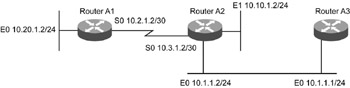
Figure 9.4:
An OSPF network.
Consider in Figure 9.4 the route 10.20.1.0/24 is not installed in the routing tables of A2 and A3.
The IP address configured in the serial link between A1 and A2 is not a part of the same subnet. Adjacency is established between the two routers successfully in a point-to-point link. OSPF does not check if the neighbors belong to the same IP subnet. Even though the neighbor relationship is developed and network 10.20.1.0/24
In Figure 9.4, consider that route 10.10.1.2/24 is not established in the routing table of A3. In this case, check if any filter is applied at the incoming direction by using the show ip protocols command. We need to suitably modify the access lists to allow installation of the network in the routing table.
This section discusses troubleshooting the problems in NBMA networks in OSPF.
Consider the example depicted in Figure 9.5. In the figure, a Frame Relay NBMA cloud is shown between routers A1, A2, A3, and A4. All the routers are not connected with each other via physical links.
Figure 9.5:
A Frame Relay NBMA network in OSPF.
OSPF considers an NBMA cloud to be similar to a broadcast based network. However, the exchange of Hello packets and DR and BDR
Configure subinterfaces as point-to-point links in the NBMA cloud.
Define the OSPF network with point-to-multipoint links in the NBMA cloud.
In this approach to solving the
Listing 9.17 Configuration of A2
|
|
interface Serial 0 no ip address encapsulation frame-relay ! interface Serial0.1 point-to-point ip address 10.10.1.1 255.255.255.252 frame-relay interface-dlci 10 ! interface Serial0.2 point-to-point ip address 10.10.2.1 255.255.255.252 frame-relay interface-dlci 15 ! interface Serial0.3 point-to-point ip address 10.10.3.1 255.255.255.252 frame-relay interface-dlci 20 !
|
|
The configuration of A1 is shown in Listing 9.18.
Listing 9.18 Configuration of A1
|
|
interface Serial 0 no ip address encapsulation frame-relay ! interface Serial0.1 point-to-point ip address 10.10.1.2 255.255.255.252 frame-relay interface-dlci 25 !
|
|
Service providers normally allocate the same subnet to all the interfaces that are part of the NBMA cloud. In the use of subinterfaces, the adjacency issue is solved, but allotting of different subnets corresponding to the subinterfaces is performed with the use of IP unnumbered on the links. However, this method is not acceptable for many network administrators as it hinders
In this approach to solve the adjacency formation problem in the NBMA network, the OSPF network is defined as point-to-multipoint. The configuration of A2 is shown in Listing 9.19.
Listing 9.19 Configuration of A2
|
|
! interface Serial 0 ip address 10.10.1.1 255.255.255.0 encapsulation frame-relay ip ospf network point-to-multipoint !
|
|
The configuration of A1 is shown in Listing 9.20.
Listing 9.20 Configuration of A1
|
|
! interface Serial 0 ip address 10.10.1.2 255.255.255.0 encapsulation frame-relay ip ospf network point-to-multipoint !
|
|
In this approach, the single subnet is used for all